2 Robotics and Microsystems Center, Scoochow University, Suzhou 215021, China* Correspondence: [email protected]; Tel.: +86-511-8444-5385
Abstract: Piezoelectric actuators usually operate under a high frequency driving signal. Here wereport a harmonic rotating piezoelectric actuator by coupling a harmonic wave generator and afriction rotor, in which the actuator can be actuated by a low-frequency sinusoidal signal withpositive bias. The harmonic wave is generated by a two-stage magnifying mechanism consistingof a displacement amplifier and a harmonic rod. Applying piezoelectricity theory, the actuator’soutput characteristic equations are deduced. What is more, the output characteristics of piezoelectricactuators are tested with the established experimental system. Results show that the generatedharmonic displacements can drive the actuator to work normally at a driving voltage of largerthan 90 V and the maximum total harmonic displacement of the piezoelectric actuator comes upto 427.6 µm under the driving voltage of 150 V. Meanwhile, the error between the measured andcalculated values of the harmonic displacement is less than 7%. Furthermore, the rotational speed ofthe piezoelectric actuator reaches 5.45 rpm/min at 150 V voltage and 5 Hz driving frequency.
Piezoelectric actuators use the inverse piezoelectric effect to convert electrical energyinto mechanical energy or mechanical motion. Due to the advantages of its simple structure,light weight and fast response, piezoelectric actuators have been used in Micro ElectroMechanical Systems (MEMS), micro-robots, bioengineering and medical sciences, as wellas fluid drive and vibration and noise control fields. Therefore, the research on piezoelectricdrive technology has great economic and social value.
Numerous achievements in piezoelectric actuating have been obtained. Acosta [1]made use of idealized piezoelectric sensors to achieve photoacoustic imaging. Using themethod of matched asymptotic expansions and the basic constitutive relations for piezoelec-tricity, the mathematical model for piezoelectric transducers was established. Through theproposed model, a better imaging effect is obtained. Wang et al. [2] designed a non-resonantstepping type bolt-clamped piezoelectric actuator. The proposed piezoelectric actuator wasoperated under a clamping and driving mechanism by using two longitudinal-bendingtransducers. Under 400 Vp-p voltages and 1 Hz signal drive, the average step distancewas about 10.8 µm. When the load mass is 1.47 kg, the actuator can obtain a velocityof 1.42 µm/s. Applying four rotating traveling wave piezoelectric actuators, Hamamotoet al. [3] designed an aircraft similar to a dragonfly. Tomoaki [4] designed and manufac-tured a super-miniature piezoelectric motor with a stator volume of 1 mm3, which becameone of the smallest piezoelectric motors in the world. In the motor, the stator consists ofa metallic cube with a through-hole and piezoelectric elements adhered to its sides. Thetorque and speed were measured experimentally. Ho et al. [5] proposed a spiral drivenpiezoelectric motor, which is driven by four piezoelectric stacks and operates in doubleshear mode, with a transmission speed of 2.137 mm/s. In addition, Shi et al. [6] proposed a
cyclic multi-degree-of-freedom piezoelectric ultrasonic motor continuously driven by fourlegs. The test results showed that the maximum output torque and maximum speed of themotor were 0.118 Nm and 55 rpm/min, respectively. Zeng et al. [7] designed and tested anew type of piezoelectric micromotor driven by asymmetric inertia impact. The resolutionof this micromotor is 0.02 µm and the maximum load is 1 kg under the drive of 100 Vvoltage and 35 Hz. What is more, actuating with ’33’ electromechanical coupling mode, asurface-bondable multilayer piezoelectric actuator [8] was developed. Mazeika et al. [9]designed a multimodal piezoelectric traveling wave actuator with a cylindrical stator.The proposed actuator is clamped at the bottom and driven by a four-phase difference ofpi/2 electric signals. Experimental results show the actuator can generate a 115 rpm/minrotation speed under constant initial conditions. Based on magnetostrictive material withsimultaneous vibration, a rotating piezoelectric actuator with simultaneous vibration inthe longitudinal direction was developed by Titsch et al. [10]. It was shown that the mag-netic field and its frequency affect the amplitude of the piezoelectric actuator. Moreover,Ostasevicius et al. [11] used the piezoelectric actuator for separation and purification ofbiological microparticles.
Furthermore, many achievements have been made in the sensor and control of piezo-electric actuators. Liu et al. [12] investigated the monolithic piezoelectric control of solitonmicrocombs. By monolithically integrating piezoelectric actuators on ultralow-loss pho-tonic circuits, soliton microcombs—a spectrum of sharp lines over a range of opticalfrequencies—can be modulated at high speeds with megahertz bandwidths. Zhu et al. [13]studied a piezoelectrically actuated fast tool servo (FTS) for the diamond turning of mi-crostructured surfaces. Utilizing the newly developed FTS, two typical microstructuredsurfaces are ultra-precisely turned. Furthermore, the feasibility of this method is proven.As precision motion of the piezoelectric ultrasonic motor is severely affected by inherentfriction, hysteresis nonlinearity and model uncertainties, Feng et al. [14] developed a novelintegral terminal sliding-mode-based adaptive integral backstepping control to solve theprecision problems. Using piezo response function and global optimization techniques,Sumit et al. [15] investigated the shape control optimization of the piezoelectric bimorph.A total of 28 piezoelectric actuators are used in the piezoelectric bimorph to generate thesinusoidal profile, elliptical profile and arbitrary deformation profile by the external load.
In the low-frequency driving field, there are also some piezoelectric applications.Nabavi et al. [16] proposed a piezoelectric MEMS vibration energy harvester that operatesat a low resonant frequency of less than 200 Hz. By taking advantage of this efficientAI-based performance estimator, the harvested voltage can increase from 2.5 V to 3.4 Vunder 0.25 g excitation. To enhance the energy harvesting performance of low-frequencyrotational motion, Mei et al. [17] proposed a quad-stable piezoelectric energy harvester. Theexperiments show that the quad-stable piezoelectric energy harvester with time-varyingpotential wells exhibits a wider operational frequency range (1–7 Hz) in rotational motion.Using liquid as an energy-capturing medium, Yang et al. [18] developed a piezoelectricvibration energy harvester, which can achieve ultralow frequency, low intensity and mul-tidirectional vibration energy harvesting in a horizontal plane. The proposed harvestercan generate 9.8 µW under an ultralow frequency of 2.6 Hz and a low intensity vibrationexcitation of 0.03 g. Modulated by an electromagnetic field, Xing et al. [19] proposed alow-frequency piezoelectric motor, which combines piezoelectric driving and magneticmodulation. Driven at a frequency of 3 Hz and a modulating voltage of 4.5 V, the outputspeed and torque are 0.1046 rad/min and 0.405 Nmm, respectively. Applying a piezoelec-tric torsional vibrator and the giant electrorheological fluid, a bidirectional non-contactrotary motor was developed by Qiu et al. [20]. At an excitation frequency of 118 Hz, theproposed motor generates 1.04 mNm torque when the electric field strength of 2 kV/mmwith 30% duty cycle is applied to the giant electrorheological fluid. What is more, Barth [21]developed a harmonic micro motor that combined a harmonic drive gearbox and stackpiezoactuators. The motor can realize low-speed motion and large output torque.
Actuators 2021, 10, 4 3 of 18
In addition to the above piezoelectric actuators, a variety of new rotary actuatorsand mechanisms based on different driving principles have appeared one after another.Yang et al. [22] presented a triboelectric micromotor coupled with a micromotor anda triboelectric nanogenerator; the proposed micromotor can be actuated by ultralow-frequency mechanical stimuli. With a sliding range of 50 mm at 0.1 Hz, the micromotor canstart to rotate and reach over 1000 rpm/min at 0.8 Hz. The maximum operation efficiencyof the triboelectric micromotor can reach 41%. For early detection of cardiovasculardisease, Pullano et al. [23] proposed a novel passive device based on the triboelectriceffect to evaluate pseudo impedance cardiography. The proposed device provides a novelmonitoring approach opening a promising alternative for continuous and remote riskassessment.
Although many accomplishments have been made in the research of piezoelectricactuators, most of the research, however, has focused on intermediate- and high-frequencydriving. The driving principle of the most traditional intermediate- and high-frequencypiezoelectric actuators uses the stator resonance to produce the large amplitude, andthen produces the motion with the rotor friction. What is more, most of the literatureon low-frequency piezoelectric mechanisms are about piezoelectric energy acquisitiondevices. A few low-frequency piezoelectric actuators use electromagnetic clamping of therotor or other principles to realize the motion between the stator and rotor. Therefore,the authors present a low-frequency harmonic rotating piezoelectric actuator. Comparedwith other piezoelectric actuators, the proposed actuator uses the harmonic friction drivebetween the harmonic rod and the rotor to transmit motion. At the same time, piezoelectricdisplacement amplifying the mechanism and harmonic rod are used to amplify the outputdisplacement of piezoelectric stacks. Therefore, the end of the harmonic rod can generatea large enough displacement, and then generate a large displacement of the harmonicmotion. In turn, it can drive the rotor to produce rotational motion.
The proposed motor has the advantages of simple structure, low output speed and lowassembly precision. Only two piezoelectric stacks are used as driving sources to generateharmonic motion. Therefore, the actuator is easy to drive and control. At the same time,because the generated harmonics are not affected by the frequency, the proposed actuatorcan work under the drive of ultralow frequency and obtain ultralow speed rotation motion.
In this paper, the operating principle of the low-frequency harmonic rotating piezo-electric actuator is presented. The design process and driving parameters of the proposedpiezoelectric actuator are analyzed. In addition, the actuator’s output characteristicsare deduced. Using experimental equipment, the output characteristics of piezoelectricactuators were tested. The results lay the theoretical and experimental foundation forthe improvement of the prototype of the low-frequency harmonic rotating piezoelectricactuator.
2. Driving Principle and Motion Analysis
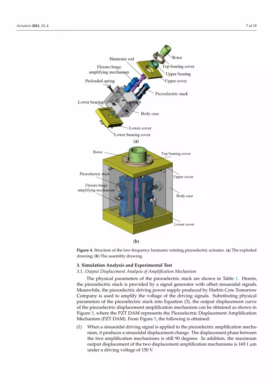
The proposed low frequency harmonic rotating piezoelectric actuator consists of adisplacement amplification mechanism, motion output mechanism and auxiliary assemblymechanism. The displacement amplification mechanism includes piezoelectric stack andflexure hinge amplifying mechanism. The motion output mechanism is composed of a rotorand harmonic rod. Moreover, the auxiliary assembly mechanism includes a top bearingcover, upper bearing, upper cover, body case, lower bearing, threaded rod and preloadedspring, lower cover and lower bearing cover.
The driving principle of the proposed piezoelectric actuator is shown in Figure 1.The actuator is driven by two sinusoidal signals with 90 degrees of the phase difference.Driven by two signals, the piezoelectric stacks generate different degrees of elongationdeformation. The deformation of piezoelectric stacks causes the deformation of the flexurehinge amplification mechanism. At the same time, the amount of deformation drivesthe harmonic rod to sway from left to right and from front to back. Under the action ofa continuous signal, the harmonic rod generates a large displacement harmonic motion.
Actuators 2021, 10, 4 4 of 18
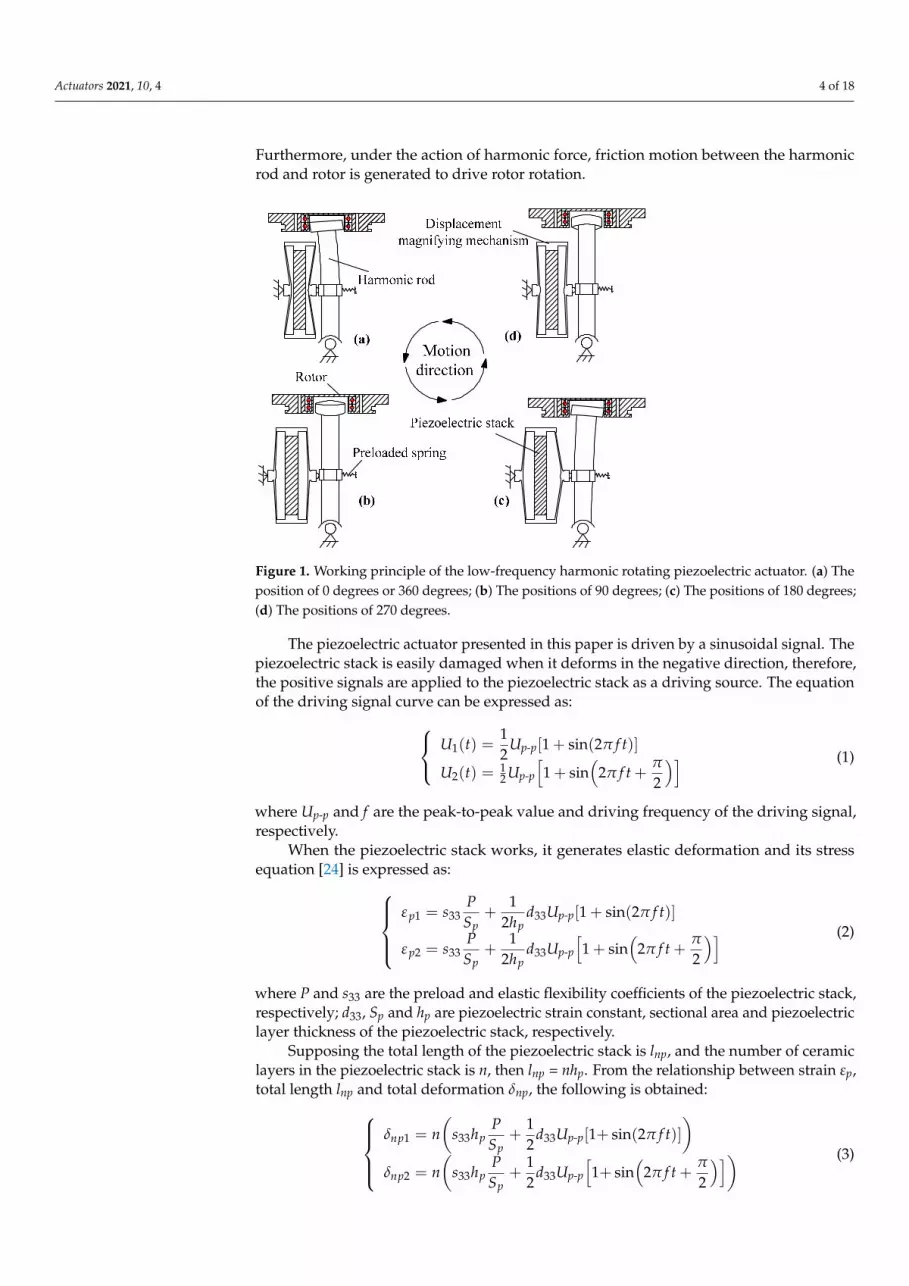
Furthermore, under the action of harmonic force, friction motion between the harmonicrod and rotor is generated to drive rotor rotation.
Actuators 2021, 10, x FOR PEER REVIEW 4 of 19
The driving principle of the proposed piezoelectric actuator is shown in Figure 1. The actuator is driven by two sinusoidal signals with 90 degrees of the phase difference. Driven by two signals, the piezoelectric stacks generate different degrees of elongation deformation. The deformation of piezoelectric stacks causes the deformation of the flex-ure hinge amplification mechanism. At the same time, the amount of deformation drives the harmonic rod to sway from left to right and from front to back. Under the action of a continuous signal, the harmonic rod generates a large displacement harmonic motion. Furthermore, under the action of harmonic force, friction motion between the harmonic rod and rotor is generated to drive rotor rotation.
Figure 1. Working principle of the low-frequency harmonic rotating piezoelectric actuator. (a) The position of 0 degrees or 360 degrees; (b) The positions of 90 degrees; (c) The positions of 180 de-grees; (d) The positions of 270 degrees.
The piezoelectric actuator presented in this paper is driven by a sinusoidal signal. The piezoelectric stack is easily damaged when it deforms in the negative direction, therefore, the positive signals are applied to the piezoelectric stack as a driving source. The equation of the driving signal curve can be expressed as:
( ) ( )
( )
1
2
1 1 sin 221 1 sin 22 2
p p
p p
U t U ft
U t U ft
π
ππ
−
−
= + = + +
(1)
where Up-p and f are the peak-to-peak value and driving frequency of the driving signal, respectively.
When the piezoelectric stack works, it generates elastic deformation and its stress equation [24] is expressed as:
( )1 33 33
2 33 33
1= + 1 sin 22
1= + 1 sin 22 2
p p pp p
p p pp p
Ps d U ftS h
Ps d U ftS h
ε π
πε π
−
−
+
+ +
(2)
where P and s33 are the preload and elastic flexibility coefficients of the piezoelectric stack, respectively; d33, Sp and hp are piezoelectric strain constant, sectional area and pie-zoelectric layer thickness of the piezoelectric stack, respectively.
Figure 1. Working principle of the low-frequency harmonic rotating piezoelectric actuator. (a) Theposition of 0 degrees or 360 degrees; (b) The positions of 90 degrees; (c) The positions of 180 degrees;(d) The positions of 270 degrees.
The piezoelectric actuator presented in this paper is driven by a sinusoidal signal. Thepiezoelectric stack is easily damaged when it deforms in the negative direction, therefore,the positive signals are applied to the piezoelectric stack as a driving source. The equationof the driving signal curve can be expressed as: U1(t) =
12
Up-p[1 + sin(2π f t)]
U2(t) = 12 Up-p
[1 + sin
(2π f t +
π
2
)] (1)
where Up-p and f are the peak-to-peak value and driving frequency of the driving signal,respectively.
When the piezoelectric stack works, it generates elastic deformation and its stressequation [24] is expressed as:
εp1 = s33PSp
+1
2hpd33Up-p[1 + sin(2π f t)]
εp2 = s33PSp
+1
2hpd33Up-p
[1 + sin
(2π f t +
π
2
)] (2)
where P and s33 are the preload and elastic flexibility coefficients of the piezoelectric stack,respectively; d33, Sp and hp are piezoelectric strain constant, sectional area and piezoelectriclayer thickness of the piezoelectric stack, respectively.
Supposing the total length of the piezoelectric stack is lnp, and the number of ceramiclayers in the piezoelectric stack is n, then lnp = nhp. From the relationship between strain εp,total length lnp and total deformation δnp, the following is obtained:
δnp1 = n(
s33hpPSp
+12
d33Up-p[1+ sin(2π f t)])
δnp2 = n(
s33hpPSp
+12
d33Up-p
[1+ sin
(2π f t +
π
2
)]) (3)
Actuators 2021, 10, 4 5 of 18
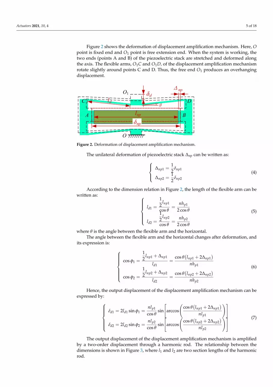
Figure 2 shows the deformation of displacement amplification mechanism. Here, Opoint is fixed end and O1 point is free extension end. When the system is working, thetwo ends (points A and B) of the piezoelectric stack are stretched and deformed alongthe axis. The flexible arms, O1C and O1D, of the displacement amplification mechanismrotate slightly around points C and D. Thus, the free end O1 produces an overhangingdisplacement.
Actuators 2021, 10, x FOR PEER REVIEW 5 of 19
Supposing the total length of the piezoelectric stack is lnp, and the number of ceram-ic layers in the piezoelectric stack is n, then lnp = nhp. From the relationship between strain εp, total length lnp and total deformation δnp, the following is obtained:
( )1 33 33
2 33 33
1= + 1+sin 22
1= + 1+sin 22 2
np p p pp
np p p pp
Pn s h d U ftS
Pn s h d U ftS
δ π
πδ π
−
−
+
(3)
Figure 2 shows the deformation of displacement amplification mechanism. Here, O point is fixed end and O1 point is free extension end. When the system is working, the two ends (points A and B) of the piezoelectric stack are stretched and deformed along the axis. The flexible arms, O1C and O1D, of the displacement amplification mechanism rotate slightly around points C and D. Thus, the free end O1 produces an overhanging displacement.
Figure 2. Deformation of displacement amplification mechanism.
The unilateral deformation of piezoelectric stack Δnp can be written as:
1 1
2 2
1=21=2
np np
np np
δ
δ
(4)
According to the dimension relation in Figure 2, the length of the flexible arm can be written as:
1 11
2 22
12=cos 2cos12=cos 2cos
npp
d
np pd
l nhl
l nhl
θ θ
θ θ
= =
(5)
where θ is the angle between the flexible arm and the horizontal. The angle between the flexible arm and the horizontal changes after deformation,
and its expression is:
( )
( )
1 1 1 11
1 1
2 2 2 22
2 2
1cos 22cos
1cos 22cos
np np np np
d p
np np np np
d p
l ll nh
l ll nh
θφ
θφ
+ Δ + Δ= =
+ Δ + Δ = =
(6)
δd
δnp
np
lnp
ld
O
O1
A B
C D
Figure 2. Deformation of displacement amplification mechanism.
The unilateral deformation of piezoelectric stack ∆np can be written as:∆np1 =
12
δnp1
∆np2 =12
δnp2
(4)
According to the dimension relation in Figure 2, the length of the flexible arm can bewritten as:
ld1 =
12
lnp1
cos θ=
nhp1
2 cos θ
ld2 =
12
lnp2
cos θ=
nhp2
2 cos θ
(5)
where θ is the angle between the flexible arm and the horizontal.The angle between the flexible arm and the horizontal changes after deformation, and
its expression is: cos φ1 =
12
lnp1 + ∆np1
ld1=
cos θ(lnp1 + 2∆np1
)nhp1
cos φ2 =
12
lnp2 + ∆np2
ld2=
cos θ(lnp2 + 2∆np2
)nhp2
(6)
Hence, the output displacement of the displacement amplification mechanism can beexpressed by:
δd1 = 2ld1 sin φ1 =nlp1
cos θsin
[arccos
(cos θ
(lnp1 + 2∆np1
)nlp1
)]
δd2 = 2ld2 sin φ2 =nlp2
cos θsin
[arccos
(cos θ
(lnp2 + 2∆np2
)nlp2
)] (7)
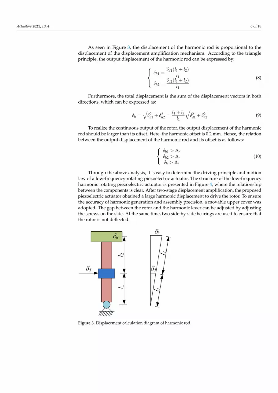
The output displacement of the displacement amplification mechanism is amplifiedby a two-order displacement through a harmonic rod. The relationship between thedimensions is shown in Figure 3, where l1 and l2 are two section lengths of the harmonicrod.
Actuators 2021, 10, 4 6 of 18
As seen in Figure 3, the displacement of the harmonic rod is proportional to thedisplacement of the displacement amplification mechanism. According to the triangleprinciple, the output displacement of the harmonic rod can be expressed by:
δh1 =δd1(l1 + l2)
l1δh2 =
δd2(l1 + l2)l1
(8)
Furthermore, the total displacement is the sum of the displacement vectors in bothdirections, which can be expressed as:
δh =√
δ2h1 + δ2
h2 =l1 + l2
l1
√δ2
d1 + δ2d2 (9)
To realize the continuous output of the rotor, the output displacement of the harmonicrod should be larger than its offset. Here, the harmonic offset is 0.2 mm. Hence, the relationbetween the output displacement of the harmonic rod and its offset is as follows:
δh1 > ∆rδh2 > ∆rδh > ∆r
(10)
Through the above analysis, it is easy to determine the driving principle and motionlaw of a low-frequency rotating piezoelectric actuator. The structure of the low-frequencyharmonic rotating piezoelectric actuator is presented in Figure 4, where the relationshipbetween the components is clear. After two-stage displacement amplification, the proposedpiezoelectric actuator obtained a large harmonic displacement to drive the rotor. To ensurethe accuracy of harmonic generation and assembly precision, a movable upper cover wasadopted. The gap between the rotor and the harmonic lever can be adjusted by adjustingthe screws on the side. At the same time, two side-by-side bearings are used to ensure thatthe rotor is not deflected.
Actuators 2021, 10, x FOR PEER REVIEW 6 of 19
Hence, the output displacement of the displacement amplification mechanism can
be expressed by:
( )
( )
1 111 1 1
1
2 222 2 2
2
cos 22 sin sin arccos
cos
cos 22 sin sin arccos
cos
np nppd d
p
np nppd d
p
lnll
nl
lnll
nl
θδ φ
θ
θδ φ
θ
+ Δ = =
+ Δ = =
(7)
The output displacement of the displacement amplification mechanism is amplified by a two-order displacement through a harmonic rod. The relationship between the di-mensions is shown in Figure 3, where l1 and l2 are two section lengths of the harmonic rod.
Figure 3. Displacement calculation diagram of harmonic rod.
As seen in Figure 3, the displacement of the harmonic rod is proportional to the displacement of the displacement amplification mechanism. According to the triangle principle, the output displacement of the harmonic rod can be expressed by:
( )
( )
1 1 21
1
2 1 22
1
dh
dh
l lll ll
δδ
δδ
+=
+ =
(8)
Furthermore, the total displacement is the sum of the displacement vectors in both directions, which can be expressed as:
2 2 2 21 21 2 1 2
1h h h d d
l ll
δ δ δ δ δ+= + = + (9)
To realize the continuous output of the rotor, the output displacement of the har-monic rod should be larger than its offset. Here, the harmonic offset is 0.2 mm. Hence, the relation between the output displacement of the harmonic rod and its offset is as follows:
d
h
d
h
Figure 3. Displacement calculation diagram of harmonic rod.
Actuators 2021, 10, 4 7 of 18
Actuators 2021, 10, x FOR PEER REVIEW 7 of 19
1
2
h r
h r
h r
δδδ
> Δ > Δ > Δ
(10)
Through the above analysis, it is easy to determine the driving principle and mo-tion law of a low-frequency rotating piezoelectric actuator. The structure of the low-frequency harmonic rotating piezoelectric actuator is presented in Figure 4, where the relationship between the components is clear. After two-stage displacement amplifi-cation, the proposed piezoelectric actuator obtained a large harmonic displacement to drive the rotor. To ensure the accuracy of harmonic generation and assembly precision, a movable upper cover was adopted. The gap between the rotor and the harmonic lever can be adjusted by adjusting the screws on the side. At the same time, two side-by-side bearings are used to ensure that the rotor is not deflected.
(a)
(b)
Figure 4. Structure of the low-frequency harmonic rotating piezoelectric actuator. (a) The exploded drawing; (b) The assembly drawing.
Figure 4. Structure of the low-frequency harmonic rotating piezoelectric actuator. (a) The explodeddrawing; (b) The assembly drawing.
3. Simulation Analysis and Experimental Test3.1. Output Displacement Analysis of Amplification Mechanism
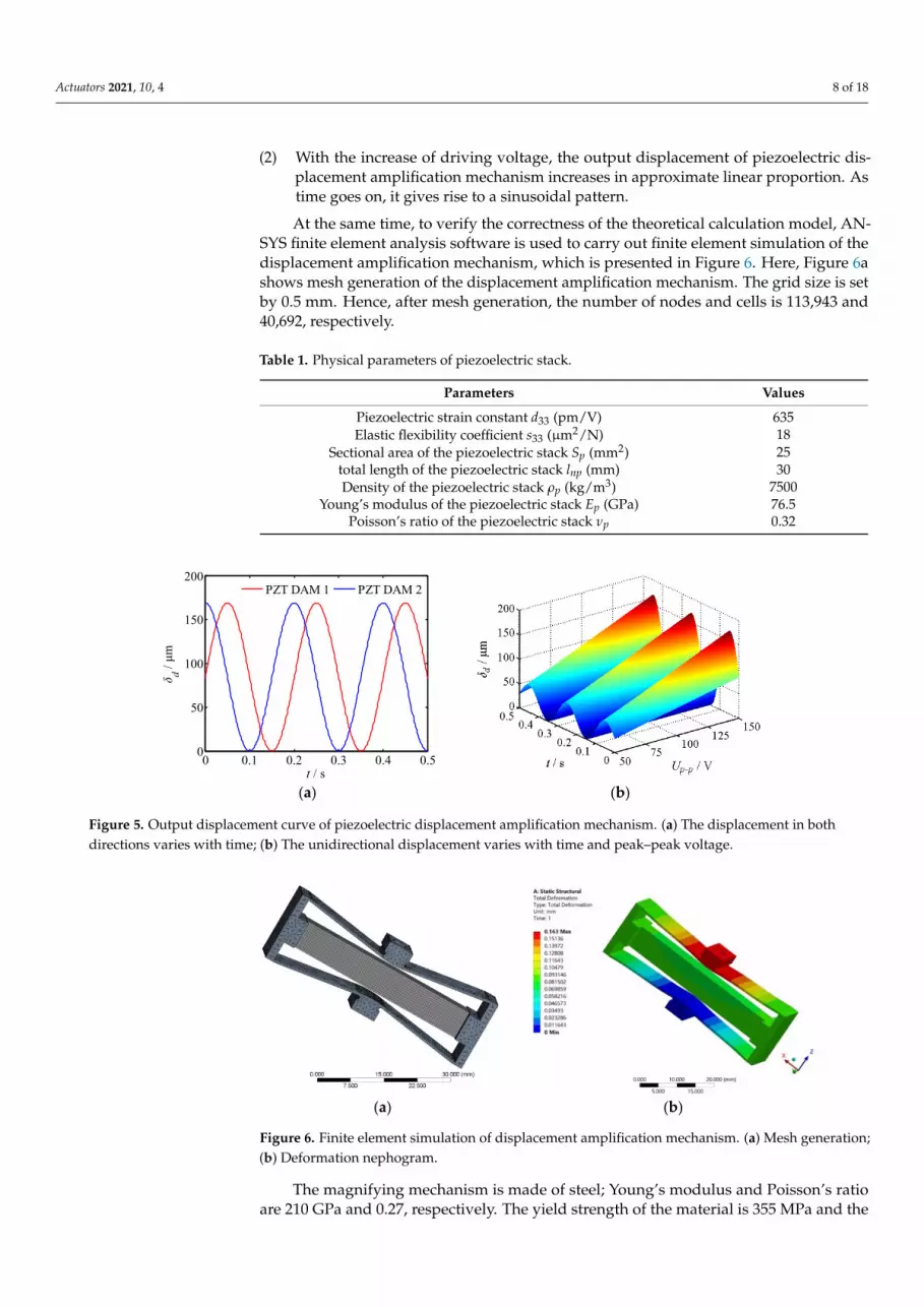
The physical parameters of the piezoelectric stack are shown in Table 1. Herein,the piezoelectric stack is provided by a signal generator with offset sinusoidal signals.Meanwhile, the piezoelectric driving power supply produced by Harbin Core TomorrowCompany is used to amplify the voltage of the driving signals. Substituting physicalparameters of the piezoelectric stack into Equation (3), the output displacement curveof the piezoelectric displacement amplification mechanism can be obtained as shown inFigure 5, where the PZT DAM represents the Piezoelectric Displacement AmplificationMechanism (PZT DAM). From Figure 5, the following is obtained:
(1) When a sinusoidal driving signal is applied to the piezoelectric amplification mecha-nism, it produces a sinusoidal displacement change. The displacement phase betweenthe two amplification mechanisms is still 90 degrees. In addition, the maximumoutput displacement of the two displacement amplification mechanisms is 169.1 µmunder a driving voltage of 150 V.
Actuators 2021, 10, 4 8 of 18
(2) With the increase of driving voltage, the output displacement of piezoelectric dis-placement amplification mechanism increases in approximate linear proportion. Astime goes on, it gives rise to a sinusoidal pattern.
At the same time, to verify the correctness of the theoretical calculation model, AN-SYS finite element analysis software is used to carry out finite element simulation of thedisplacement amplification mechanism, which is presented in Figure 6. Here, Figure 6ashows mesh generation of the displacement amplification mechanism. The grid size is setby 0.5 mm. Hence, after mesh generation, the number of nodes and cells is 113,943 and40,692, respectively.
Table 1. Physical parameters of piezoelectric stack.
Sectional area of the piezoelectric stack Sp (mm2) 25total length of the piezoelectric stack lnp (mm) 30Density of the piezoelectric stack ρp (kg/m3) 7500
Young’s modulus of the piezoelectric stack Ep (GPa) 76.5Poisson’s ratio of the piezoelectric stack νp 0.32
Actuators 2021, 10, x FOR PEER REVIEW 8 of 19
3. Simulation Analysis and Experimental Test 3.1. Output Displacement Analysis of Amplification Mechanism
The physical parameters of the piezoelectric stack are shown in Table 1. Herein, the piezoelectric stack is provided by a signal generator with offset sinusoidal signals. Meanwhile, the piezoelectric driving power supply produced by Harbin Core Tomor-row Company is used to amplify the voltage of the driving signals. Substituting physical parameters of the piezoelectric stack into Equation (3), the output displacement curve of the piezoelectric displacement amplification mechanism can be obtained as shown in Figure 5, where the PZT DAM represents the Piezoelectric Displacement Amplification Mechanism (PZT DAM). From Figure 5, the following is obtained:
(1) When a sinusoidal driving signal is applied to the piezoelectric amplification mechanism, it produces a sinusoidal displacement change. The displacement phase be-tween the two amplification mechanisms is still 90 degrees. In addition, the maximum output displacement of the two displacement amplification mechanisms is 169.1 μm under a driving voltage of 150 V.
(2) With the increase of driving voltage, the output displacement of piezoelectric displacement amplification mechanism increases in approximate linear proportion. As time goes on, it gives rise to a sinusoidal pattern.
Table 1. Physical parameters of piezoelectric stack.
Sectional area of the piezoelectric stack Sp (mm2) 25 total length of the piezoelectric stack lnp (mm) 30 Density of the piezoelectric stack ρp (kg/m3) 7500
Young's modulus of the piezoelectric stack Ep (GPa) 76.5 Poisson's ratio of the piezoelectric stack νp 0.32
(a) (b)
Figure 5. Output displacement curve of piezoelectric displacement amplification mechanism. (a) The displacement in both directions varies with time; (b) The unidirectional displacement varies with time and peak–peak voltage.
At the same time, to verify the correctness of the theoretical calculation model, ANSYS finite element analysis software is used to carry out finite element simulation of the displacement amplification mechanism, which is presented in Figure 6. Here, Figure 6a shows mesh generation of the displacement amplification mechanism. The grid size is set by 0.5 mm. Hence, after mesh generation, the number of nodes and cells is 113,943 and 40,692, respectively.
0 0.1 0.2 0.3 0.4 0.50
50
100
150
200
t / s
δ d / μm
PZT DAM 1 PZT DAM 2
Figure 5. Output displacement curve of piezoelectric displacement amplification mechanism. (a) The displacement in bothdirections varies with time; (b) The unidirectional displacement varies with time and peak–peak voltage.
Actuators 2021, 10, x FOR PEER REVIEW 9 of 19
(a) (b)
Figure 6. Finite element simulation of displacement amplification mechanism. (a) Mesh generation; (b) Deformation nephogram.
The magnifying mechanism is made of steel; Young's modulus and Poisson's ratio are 210 GPa and 0.27, respectively. The yield strength of the material is 355 MPa and the density is 7850 kg/m3. However, Young's modulus and Poisson's ratio of the piezoelec-tric material are 76.5 GPa and 0.32, respectively. Meanwhile, the density of the piezoe-lectric material is 7500 kg/m3.
A fixed constraint is adopted at one end of the amplification mechanism, as shown in point O in Figure 2. As the selected piezoelectric stack can output a displacement of 30 μm, a displacement load of 30 μm is applied to both ends of the piezoelectric stack.
After finite element simulation, the deformation cloud diagram of the displacement amplification mechanism is shown in Figure 6b. From the figure, we see that the finite element simulation shows that the maximum output displacement of the displacement amplification mechanism is 163 μm. Hence, the error between the simulation value and the theoretical calculation value is 3.6%. The results indicate that the theoretical calcula-tion model is reasonable.
Meanwhile, the output displacement experiment of piezoelectric displacement am-plification mechanism is carried out to further verify the correctness of the theoretical calculation. The displacement amplification mechanisms and piezoelectric stacks for the experiment were manufactured by the Harbin Tiny Nano Company. Figure 7 presents the experimental test system for the piezoelectric displacement amplification mechanism. Here, the piezoelectric drive power supply adopts the three-channel power supply pro-duced by the Harbin Core Tomorrow Company. The output displacement of the piezoe-lectric displacement amplifier is measured by LVDT inductance micro displacement measuring instrument. In addition, JUNTEK JDS-2900 signal generator was used to pro-vide sinusoidal drive signals for the piezoelectric stacks. The experimental results of output displacement are shown in Figure 8, where Figure 8a–c represents the measured displacement of piezoelectric displacement amplification mechanisms 1 and 2, as well as the error between the measured value and the theoretical value, respectively. The ex-perimental results indicate that:
(1) Compared with the theoretical calculation, the experimental curve of piezoelec-tric displacement amplification mechanism presents a weak nonlinear variation with the peak–peak voltage change. Driven by a 150 V voltage signal, the maximum output dis-placements of the two displacement amplification mechanisms are 166 μm and 163 μm, respectively.
(2) With the increase of voltage, the experimental error decreases first and then in-creases, and the error is the smallest when the voltage is 90–100 V. At the same time, the lower the voltage, the greater the error, therefore the lower voltage is not suitable for driving piezoelectric displacement amplification mechanism
(3) When the voltage is within the range of 60–150 V, the output displacement error is within 5%. Within this voltage range, the error of displacement amplification mecha-
Figure 6. Finite element simulation of displacement amplification mechanism. (a) Mesh generation;(b) Deformation nephogram.
The magnifying mechanism is made of steel; Young’s modulus and Poisson’s ratioare 210 GPa and 0.27, respectively. The yield strength of the material is 355 MPa and the
Actuators 2021, 10, 4 9 of 18
density is 7850 kg/m3. However, Young’s modulus and Poisson’s ratio of the piezoelectricmaterial are 76.5 GPa and 0.32, respectively. Meanwhile, the density of the piezoelectricmaterial is 7500 kg/m3.
A fixed constraint is adopted at one end of the amplification mechanism, as shown inpoint O in Figure 2. As the selected piezoelectric stack can output a displacement of 30 µm,a displacement load of 30 µm is applied to both ends of the piezoelectric stack.
After finite element simulation, the deformation cloud diagram of the displacementamplification mechanism is shown in Figure 6b. From the figure, we see that the finiteelement simulation shows that the maximum output displacement of the displacementamplification mechanism is 163 µm. Hence, the error between the simulation value andthe theoretical calculation value is 3.6%. The results indicate that the theoretical calculationmodel is reasonable.
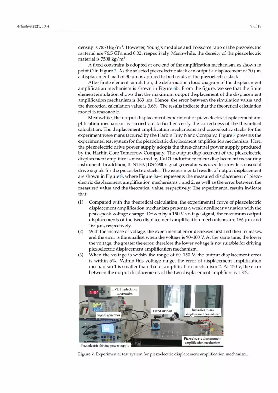
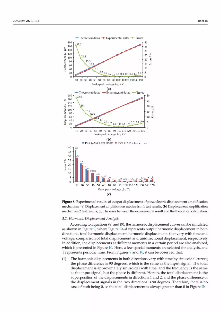
Meanwhile, the output displacement experiment of piezoelectric displacement am-plification mechanism is carried out to further verify the correctness of the theoreticalcalculation. The displacement amplification mechanisms and piezoelectric stacks for theexperiment were manufactured by the Harbin Tiny Nano Company. Figure 7 presents theexperimental test system for the piezoelectric displacement amplification mechanism. Here,the piezoelectric drive power supply adopts the three-channel power supply producedby the Harbin Core Tomorrow Company. The output displacement of the piezoelectricdisplacement amplifier is measured by LVDT inductance micro displacement measuringinstrument. In addition, JUNTEK JDS-2900 signal generator was used to provide sinusoidaldrive signals for the piezoelectric stacks. The experimental results of output displacementare shown in Figure 8, where Figure 8a–c represents the measured displacement of piezo-electric displacement amplification mechanisms 1 and 2, as well as the error between themeasured value and the theoretical value, respectively. The experimental results indicatethat:
(1) Compared with the theoretical calculation, the experimental curve of piezoelectricdisplacement amplification mechanism presents a weak nonlinear variation with thepeak–peak voltage change. Driven by a 150 V voltage signal, the maximum outputdisplacements of the two displacement amplification mechanisms are 166 µm and163 µm, respectively.
(2) With the increase of voltage, the experimental error decreases first and then increases,and the error is the smallest when the voltage is 90–100 V. At the same time, the lowerthe voltage, the greater the error, therefore the lower voltage is not suitable for drivingpiezoelectric displacement amplification mechanism.
(3) When the voltage is within the range of 60–150 V, the output displacement erroris within 5%. Within this voltage range, the error of displacement amplificationmechanism 1 is smaller than that of amplification mechanism 2. At 150 V, the errorbetween the output displacements of the two displacement amplifiers is 1.8%.
Actuators 2021, 10, x FOR PEER REVIEW 10 of 19
nism 1 is smaller than that of amplification mechanism 2. At 150 V, the error between the output displacements of the two displacement amplifiers is 1.8%.
Figure 7. Experimental test system for piezoelectric displacement amplification mechanism.
(a)
(b)
(c)
Figure 8. Experimental results of output displacement of piezoelectric displacement amplification mechanism. (a) Displacement amplification mechanism 1 test results; (b) Displacement amplifica-tion mechanism 2 test results; (c) The error between the experimental result and the theoretical calculation.
Figure 7. Experimental test system for piezoelectric displacement amplification mechanism.
Actuators 2021, 10, 4 10 of 18
Actuators 2021, 10, x FOR PEER REVIEW 10 of 19
nism 1 is smaller than that of amplification mechanism 2. At 150 V, the error between the output displacements of the two displacement amplifiers is 1.8%.
Figure 7. Experimental test system for piezoelectric displacement amplification mechanism.
(a)
(b)
(c)
Figure 8. Experimental results of output displacement of piezoelectric displacement amplification mechanism. (a) Displacement amplification mechanism 1 test results; (b) Displacement amplifica-tion mechanism 2 test results; (c) The error between the experimental result and the theoretical calculation.
Figure 8. Experimental results of output displacement of piezoelectric displacement amplificationmechanism. (a) Displacement amplification mechanism 1 test results; (b) Displacement amplificationmechanism 2 test results; (c) The error between the experimental result and the theoretical calculation.
3.2. Harmonic Displacement Analysis
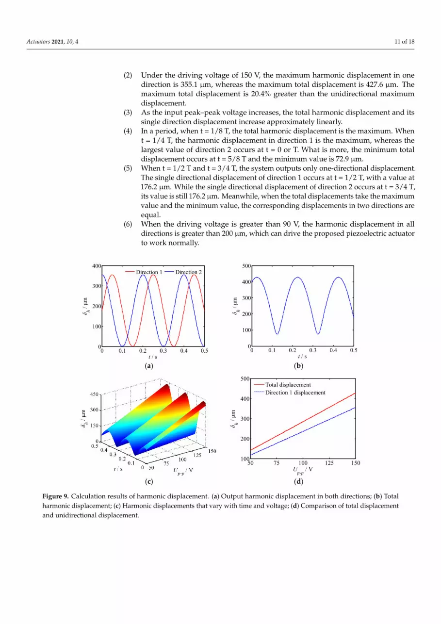
According to Equations (8) and (9), the harmonic displacement curves can be simulatedas shown in Figure 9, where Figure 9a–d represents output harmonic displacement in bothdirections, total harmonic displacement, harmonic displacements that vary with time andvoltage, comparison of total displacement and unidirectional displacement, respectively.In addition, the displacements at different moments in a certain period are also analyzed,which is presented in Figure 10. Here, a few special moments are selected for analysis, andT represents periodic time. From Figures 9 and 10, it can be observed that:
(1) The harmonic displacements in both directions vary with time by sinusoidal curves;the phase difference is 90 degrees, which is the same as the input signal. The totaldisplacement is approximately sinusoidal with time, and the frequency is the sameas the input signal, but the phase is different. Herein, the total displacement is thesuperposition of the displacements in directions 1 and 2, and the phase difference ofthe displacement signals in the two directions is 90 degrees. Therefore, there is nocase of both being 0, so the total displacement is always greater than 0 in Figure 9b.
Actuators 2021, 10, 4 11 of 18
(2) Under the driving voltage of 150 V, the maximum harmonic displacement in onedirection is 355.1 µm, whereas the maximum total displacement is 427.6 µm. Themaximum total displacement is 20.4% greater than the unidirectional maximumdisplacement.
(3) As the input peak–peak voltage increases, the total harmonic displacement and itssingle direction displacement increase approximately linearly.
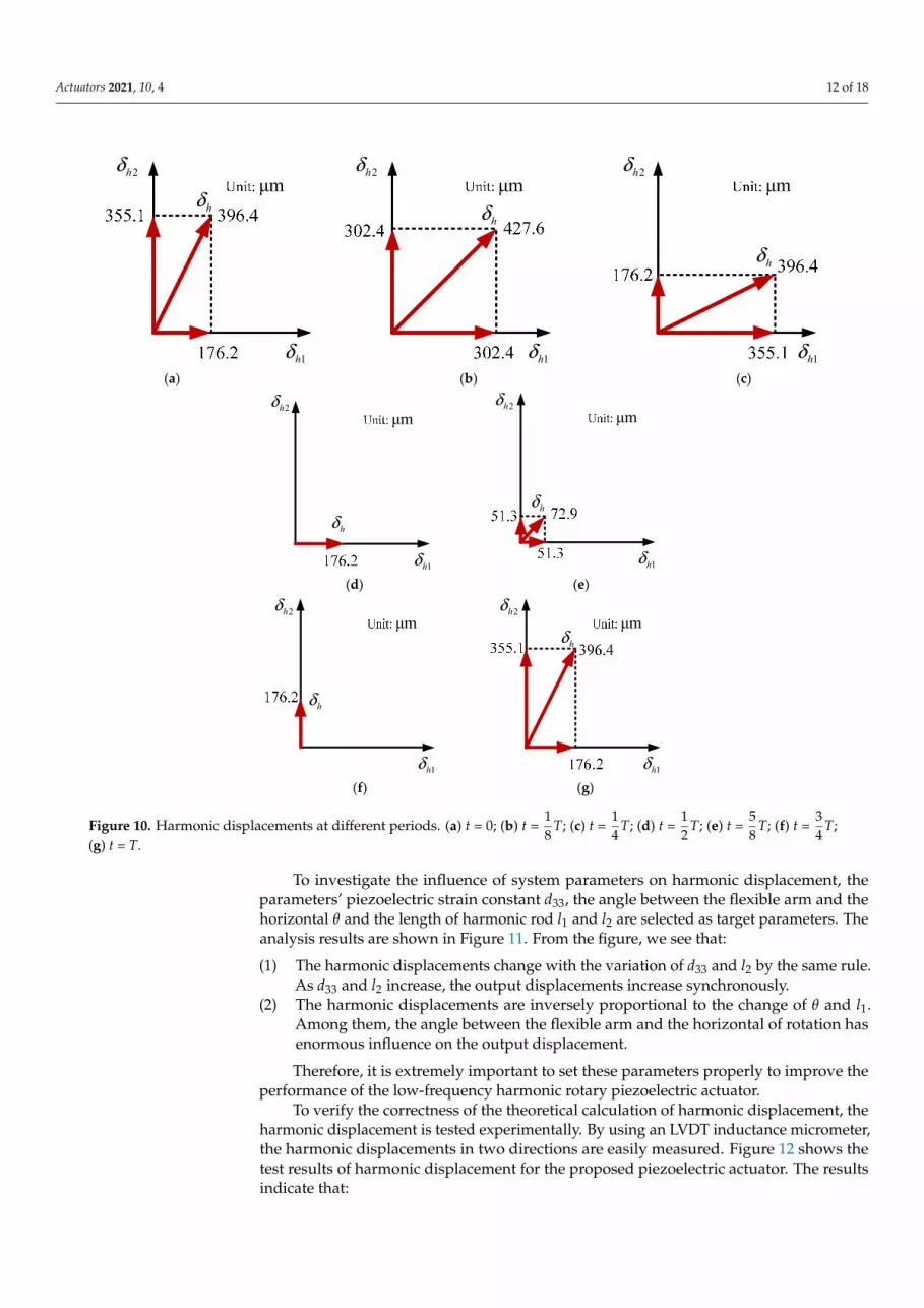
(4) In a period, when t = 1/8 T, the total harmonic displacement is the maximum. Whent = 1/4 T, the harmonic displacement in direction 1 is the maximum, whereas thelargest value of direction 2 occurs at t = 0 or T. What is more, the minimum totaldisplacement occurs at t = 5/8 T and the minimum value is 72.9 µm.
(5) When t = 1/2 T and t = 3/4 T, the system outputs only one-directional displacement.The single directional displacement of direction 1 occurs at t = 1/2 T, with a value at176.2 µm. While the single directional displacement of direction 2 occurs at t = 3/4 T,its value is still 176.2 µm. Meanwhile, when the total displacements take the maximumvalue and the minimum value, the corresponding displacements in two directions areequal.
(6) When the driving voltage is greater than 90 V, the harmonic displacement in alldirections is greater than 200 µm, which can drive the proposed piezoelectric actuatorto work normally.
Actuators 2021, 10, x FOR PEER REVIEW 11 of 19
3.2. Harmonic Displacement Analysis According to Equations (8) and (9), the harmonic displacement curves can be simu-
lated as shown in Figure 9, where Figure 9a–d represents output harmonic displacement in both directions, total harmonic displacement, harmonic displacements that vary with time and voltage, comparison of total displacement and unidirectional displacement, respectively. In addition, the displacements at different moments in a certain period are also analyzed, which is presented in Figure 10. Here, a few special moments are selected for analysis, and T represents periodic time. From Figures 9 and 10, it can be observed that:
(1) The harmonic displacements in both directions vary with time by sinusoidal curves; the phase difference is 90 degrees, which is the same as the input signal. The to-tal displacement is approximately sinusoidal with time, and the frequency is the same as the input signal, but the phase is different. Herein, the total displacement is the superpo-sition of the displacements in directions 1 and 2, and the phase difference of the dis-placement signals in the two directions is 90 degrees. Therefore, there is no case of both being 0, so the total displacement is always greater than 0 in Figure 9b.
(2) Under the driving voltage of 150 V, the maximum harmonic displacement in one direction is 355.1 μm, whereas the maximum total displacement is 427.6 μm. The maxi-mum total displacement is 20.4% greater than the unidirectional maximum displace-ment.
(3) As the input peak–peak voltage increases, the total harmonic displacement and its single direction displacement increase approximately linearly.
(4) In a period, when t = 1/8 T, the total harmonic displacement is the maximum. When t = 1/4 T, the harmonic displacement in direction 1 is the maximum, whereas the largest value of direction 2 occurs at t = 0 or T. What is more, the minimum total dis-placement occurs at t = 5/8 T and the minimum value is 72.9 μm.
(5) When t =1/2 T and t = 3/4 T, the system outputs only one-directional displace-ment. The single directional displacement of direction 1 occurs at t =1/2 T, with a value at 176.2 μm. While the single directional displacement of direction 2 occurs at t =3/4 T, its value is still 176.2 μm. Meanwhile, when the total displacements take the maximum value and the minimum value, the corresponding displacements in two directions are equal.
(6) When the driving voltage is greater than 90 V, the harmonic displacement in all directions is greater than 200 μm, which can drive the proposed piezoelectric actuator to work normally.
(a) (b)
0 0.1 0.2 0.3 0.4 0.50
100
200
300
400
t / s
δ h / μm
Direction 1 Direction 2
0 0.1 0.2 0.3 0.4 0.50
100
200
300
400
500
t / s
δ h / μm
Actuators 2021, 10, x FOR PEER REVIEW 12 of 19
(c) (d)
Figure 9. Calculation results of harmonic displacement. (a) Output harmonic displacement in both directions; (b) Total harmonic displacement; (c) Harmonic displacements that vary with time and voltage; (d) Comparison of total displacement and unidirectional displacement.
(a) (b) (c)
(d) (e)
(f) (g)
Figure 10. Harmonic displacements at different periods. (a) t = 0; (b) t = 𝑇; (c) t = 𝑇; (d) t = 𝑇; (e) t = 𝑇; (f) t = 𝑇; (g) t = T.
To investigate the influence of system parameters on harmonic displacement, the parameters’ piezoelectric strain constant d33, the angle between the flexible arm and the
50 75 100 125 150100
200
300
400
500
Up-p / V
δ h / μm
Total displacementDirection 1 displacement
1hδ
2hδμm
1hδ
2hδμm
hδ
hδ
1hδ
2hδμm
hδ
1hδ
2hδμm
hδ
1hδ
2hδμm
hδ
1hδ
2hδμm
1hδ
2hδμm
hδ
hδ
Figure 9. Calculation results of harmonic displacement. (a) Output harmonic displacement in both directions; (b) Totalharmonic displacement; (c) Harmonic displacements that vary with time and voltage; (d) Comparison of total displacementand unidirectional displacement.
Actuators 2021, 10, 4 12 of 18
Actuators 2021, 10, x FOR PEER REVIEW 12 of 19
(c) (d)
Figure 9. Calculation results of harmonic displacement. (a) Output harmonic displacement in both directions; (b) Total harmonic displacement; (c) Harmonic displacements that vary with time and voltage; (d) Comparison of total displacement and unidirectional displacement.
(a) (b) (c)
(d) (e)
(f) (g)
Figure 10. Harmonic displacements at different periods. (a) t = 0; (b) t = 𝑇; (c) t = 𝑇; (d) t = 𝑇; (e) t = 𝑇; (f) t = 𝑇; (g) t = T.
To investigate the influence of system parameters on harmonic displacement, the parameters’ piezoelectric strain constant d33, the angle between the flexible arm and the
50 75 100 125 150100
200
300
400
500
Up-p / V
δ h / μm
Total displacementDirection 1 displacement
1hδ
2hδμm
1hδ
2hδμm
hδ
hδ
1hδ
2hδμm
hδ
1hδ
2hδμm
hδ
1hδ
2hδμm
hδ
1hδ
2hδμm
1hδ
2hδμm
hδ
hδ
Figure 10. Harmonic displacements at different periods. (a) t = 0; (b) t =18
T; (c) t =14
T; (d) t =12
T; (e) t =58
T; (f) t =34
T;(g) t = T.
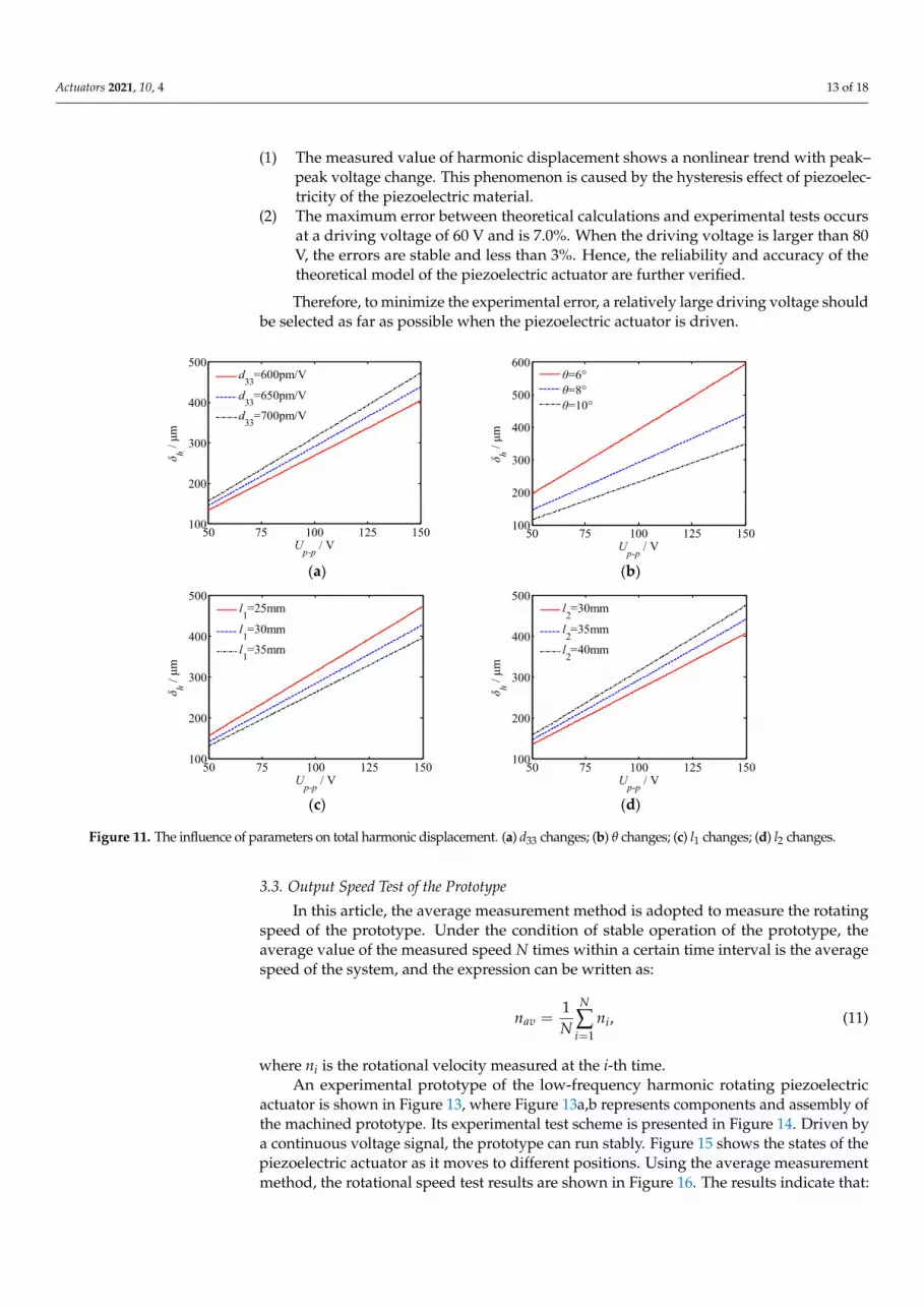
To investigate the influence of system parameters on harmonic displacement, theparameters’ piezoelectric strain constant d33, the angle between the flexible arm and thehorizontal θ and the length of harmonic rod l1 and l2 are selected as target parameters. Theanalysis results are shown in Figure 11. From the figure, we see that:
(1) The harmonic displacements change with the variation of d33 and l2 by the same rule.As d33 and l2 increase, the output displacements increase synchronously.
(2) The harmonic displacements are inversely proportional to the change of θ and l1.Among them, the angle between the flexible arm and the horizontal of rotation hasenormous influence on the output displacement.
Therefore, it is extremely important to set these parameters properly to improve theperformance of the low-frequency harmonic rotary piezoelectric actuator.
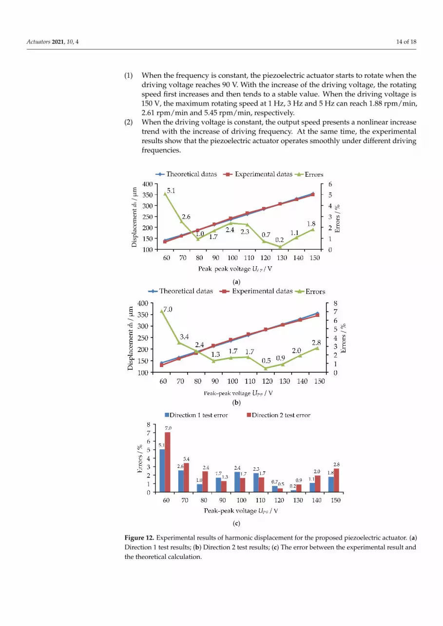
To verify the correctness of the theoretical calculation of harmonic displacement, theharmonic displacement is tested experimentally. By using an LVDT inductance micrometer,the harmonic displacements in two directions are easily measured. Figure 12 shows thetest results of harmonic displacement for the proposed piezoelectric actuator. The resultsindicate that:
Actuators 2021, 10, 4 13 of 18
(1) The measured value of harmonic displacement shows a nonlinear trend with peak–peak voltage change. This phenomenon is caused by the hysteresis effect of piezoelec-tricity of the piezoelectric material.
(2) The maximum error between theoretical calculations and experimental tests occursat a driving voltage of 60 V and is 7.0%. When the driving voltage is larger than 80V, the errors are stable and less than 3%. Hence, the reliability and accuracy of thetheoretical model of the piezoelectric actuator are further verified.
Therefore, to minimize the experimental error, a relatively large driving voltage shouldbe selected as far as possible when the piezoelectric actuator is driven.
Actuators 2021, 10, x FOR PEER REVIEW 13 of 19
horizontal θ and the length of harmonic rod l1 and l2 are selected as target parameters. The analysis results are shown in Figure 11. From the figure, we see that:
(1) The harmonic displacements change with the variation of d33 and l2 by the same rule. As d33 and l2 increase, the output displacements increase synchronously.
(2) The harmonic displacements are inversely proportional to the change of θ and l1. Among them, the angle between the flexible arm and the horizontal of rotation has enormous influence on the output displacement.
Therefore, it is extremely important to set these parameters properly to improve the performance of the low-frequency harmonic rotary piezoelectric actuator.
(a) (b)
(c) (d)
Figure 11. The influence of parameters on total harmonic displacement. (a) d33 changes; (b) θ changes; (c) l1 changes; (d) l2 changes.
To verify the correctness of the theoretical calculation of harmonic displacement, the harmonic displacement is tested experimentally. By using an LVDT inductance microm-eter, the harmonic displacements in two directions are easily measured. Figure 12 shows the test results of harmonic displacement for the proposed piezoelectric actuator. The results indicate that:
(1) The measured value of harmonic displacement shows a nonlinear trend with peak–peak voltage change. This phenomenon is caused by the hysteresis effect of piezo-electricity of the piezoelectric material.
(2) The maximum error between theoretical calculations and experimental tests oc-curs at a driving voltage of 60 V and is 7.0%. When the driving voltage is larger than 80 V, the errors are stable and less than 3%. Hence, the reliability and accuracy of the theo-retical model of the piezoelectric actuator are further verified.
Therefore, to minimize the experimental error, a relatively large driving voltage should be selected as far as possible when the piezoelectric actuator is driven.
50 75 100 125 150100
200
300
400
500
Up-p / V
δ h / μm
d33=600pm/V
d33=650pm/Vd33=700pm/V
50 75 100 125 150100
200
300
400
500
600
Up-p / V
δ h / μm
θ=6°θ=8°θ=10°
50 75 100 125 150100
200
300
400
500
Up-p / V
δ h / μm
l1=25mm
l1=30mml1=35mm
50 75 100 125 150100
200
300
400
500
Up-p / V
δ h / μm
l2=30mm
l2=35mml2=40mm
Figure 11. The influence of parameters on total harmonic displacement. (a) d33 changes; (b) θ changes; (c) l1 changes; (d) l2 changes.
3.3. Output Speed Test of the Prototype
In this article, the average measurement method is adopted to measure the rotatingspeed of the prototype. Under the condition of stable operation of the prototype, theaverage value of the measured speed N times within a certain time interval is the averagespeed of the system, and the expression can be written as:
nav =1N
N
∑i=1
ni, (11)
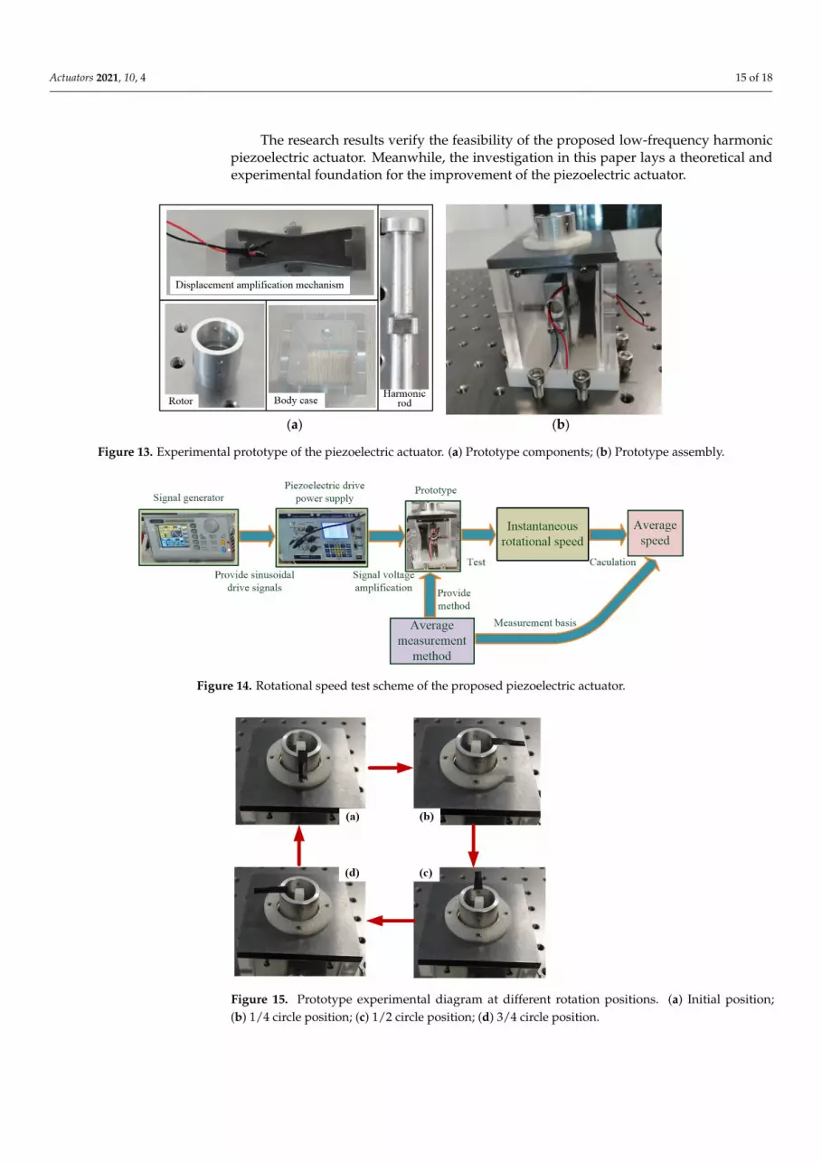
where ni is the rotational velocity measured at the i-th time.An experimental prototype of the low-frequency harmonic rotating piezoelectric
actuator is shown in Figure 13, where Figure 13a,b represents components and assembly ofthe machined prototype. Its experimental test scheme is presented in Figure 14. Driven bya continuous voltage signal, the prototype can run stably. Figure 15 shows the states of thepiezoelectric actuator as it moves to different positions. Using the average measurementmethod, the rotational speed test results are shown in Figure 16. The results indicate that:
Actuators 2021, 10, 4 14 of 18
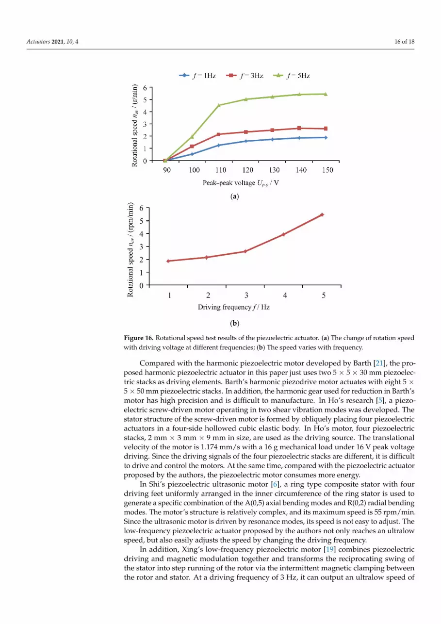
(1) When the frequency is constant, the piezoelectric actuator starts to rotate when thedriving voltage reaches 90 V. With the increase of the driving voltage, the rotatingspeed first increases and then tends to a stable value. When the driving voltage is150 V, the maximum rotating speed at 1 Hz, 3 Hz and 5 Hz can reach 1.88 rpm/min,2.61 rpm/min and 5.45 rpm/min, respectively.
(2) When the driving voltage is constant, the output speed presents a nonlinear increasetrend with the increase of driving frequency. At the same time, the experimentalresults show that the piezoelectric actuator operates smoothly under different drivingfrequencies.
Actuators 2021, 10, x FOR PEER REVIEW 14 of 19
(a)
(b)
(c)
Figure 12. Experimental results of harmonic displacement for the proposed piezoelectric actuator. (a) Direction 1 test results; (b) Direction 2 test results; (c) The error between the experimental result and the theoretical calculation.
3.3. Output Speed Test of the Prototype In this article, the average measurement method is adopted to measure the rotating
speed of the prototype. Under the condition of stable operation of the prototype, the av-erage value of the measured speed N times within a certain time interval is the average speed of the system, and the expression can be written as:
Dis
plac
emen
t dh
/ μm
Erro
rs /
%
Figure 12. Experimental results of harmonic displacement for the proposed piezoelectric actuator. (a)Direction 1 test results; (b) Direction 2 test results; (c) The error between the experimental result andthe theoretical calculation.
Actuators 2021, 10, 4 15 of 18
The research results verify the feasibility of the proposed low-frequency harmonicpiezoelectric actuator. Meanwhile, the investigation in this paper lays a theoretical andexperimental foundation for the improvement of the piezoelectric actuator.
Actuators 2021, 10, x FOR PEER REVIEW 15 of 19
1
1 N
av ii
n nN =
= , (11)
where ni is the rotational velocity measured at the i-th time. An experimental prototype of the low-frequency harmonic rotating piezoelectric
actuator is shown in Figure 13, where Figure 13a,b represents components and assembly of the machined prototype. Its experimental test scheme is presented in Figure 14. Driv-en by a continuous voltage signal, the prototype can run stably. Figure 15 shows the states of the piezoelectric actuator as it moves to different positions. Using the average measurement method, the rotational speed test results are shown in Figure 16. The re-sults indicate that:
(1) When the frequency is constant, the piezoelectric actuator starts to rotate when the driving voltage reaches 90 V. With the increase of the driving voltage, the rotating speed first increases and then tends to a stable value. When the driving voltage is 150 V, the maximum rotating speed at 1 Hz, 3 Hz and 5 Hz can reach 1.88 rpm/min, 2.61 rpm/min and 5.45 rpm/min, respectively.
(2) When the driving voltage is constant, the output speed presents a nonlinear in-crease trend with the increase of driving frequency. At the same time, the experimental results show that the piezoelectric actuator operates smoothly under different driving frequencies.
(a) (b)
Figure 13. Experimental prototype of the piezoelectric actuator. (a) Prototype components; (b) Prototype assembly.
Figure 14. Rotational speed test scheme of the proposed piezoelectric actuator.
Figure 13. Experimental prototype of the piezoelectric actuator. (a) Prototype components; (b) Prototype assembly.
Actuators 2021, 10, x FOR PEER REVIEW 15 of 19
1
1 N
av ii
n nN =
= , (11)
where ni is the rotational velocity measured at the i-th time. An experimental prototype of the low-frequency harmonic rotating piezoelectric
actuator is shown in Figure 13, where Figure 13a,b represents components and assembly of the machined prototype. Its experimental test scheme is presented in Figure 14. Driv-en by a continuous voltage signal, the prototype can run stably. Figure 15 shows the states of the piezoelectric actuator as it moves to different positions. Using the average measurement method, the rotational speed test results are shown in Figure 16. The re-sults indicate that:
(1) When the frequency is constant, the piezoelectric actuator starts to rotate when the driving voltage reaches 90 V. With the increase of the driving voltage, the rotating speed first increases and then tends to a stable value. When the driving voltage is 150 V, the maximum rotating speed at 1 Hz, 3 Hz and 5 Hz can reach 1.88 rpm/min, 2.61 rpm/min and 5.45 rpm/min, respectively.
(2) When the driving voltage is constant, the output speed presents a nonlinear in-crease trend with the increase of driving frequency. At the same time, the experimental results show that the piezoelectric actuator operates smoothly under different driving frequencies.
(a) (b)
Figure 13. Experimental prototype of the piezoelectric actuator. (a) Prototype components; (b) Prototype assembly.
Figure 14. Rotational speed test scheme of the proposed piezoelectric actuator. Figure 14. Rotational speed test scheme of the proposed piezoelectric actuator.
Actuators 2021, 10, x FOR PEER REVIEW 16 of 19
Figure 15. Prototype experimental diagram at different rotation positions. (a) Initial position; (b) 1/4 circle position; (c) 1/2 circle position; (d) 3/4 circle position.
(a)
(b)
Figure 16. Rotational speed test results of the piezoelectric actuator. (a) The change of rotation speed with driving voltage at different frequencies; (b) The speed varies with frequency.
The research results verify the feasibility of the proposed low-frequency harmonic piezoelectric actuator. Meanwhile, the investigation in this paper lays a theoretical and experimental foundation for the improvement of the piezoelectric actuator.
Compared with the harmonic piezoelectric motor developed by Barth [21], the proposed harmonic piezoelectric actuator in this paper just uses two 5 × 5 × 30 mm pie-
0123456
1 2 3 4 5Driving frequency f / Hz
Figure 15. Prototype experimental diagram at different rotation positions. (a) Initial position;(b) 1/4 circle position; (c) 1/2 circle position; (d) 3/4 circle position.
Actuators 2021, 10, 4 16 of 18
Actuators 2021, 10, x FOR PEER REVIEW 16 of 19
Figure 15. Prototype experimental diagram at different rotation positions. (a) Initial position; (b) 1/4 circle position; (c) 1/2 circle position; (d) 3/4 circle position.
(a)
(b)
Figure 16. Rotational speed test results of the piezoelectric actuator. (a) The change of rotation speed with driving voltage at different frequencies; (b) The speed varies with frequency.
The research results verify the feasibility of the proposed low-frequency harmonic piezoelectric actuator. Meanwhile, the investigation in this paper lays a theoretical and experimental foundation for the improvement of the piezoelectric actuator.
Compared with the harmonic piezoelectric motor developed by Barth [21], the proposed harmonic piezoelectric actuator in this paper just uses two 5 × 5 × 30 mm pie-
0123456
1 2 3 4 5Driving frequency f / Hz
Figure 16. Rotational speed test results of the piezoelectric actuator. (a) The change of rotation speedwith driving voltage at different frequencies; (b) The speed varies with frequency.
Compared with the harmonic piezoelectric motor developed by Barth [21], the pro-posed harmonic piezoelectric actuator in this paper just uses two 5 × 5 × 30 mm piezoelec-tric stacks as driving elements. Barth’s harmonic piezodrive motor actuates with eight 5 ×5 × 50 mm piezoelectric stacks. In addition, the harmonic gear used for reduction in Barth’smotor has high precision and is difficult to manufacture. In Ho’s research [5], a piezo-electric screw-driven motor operating in two shear vibration modes was developed. Thestator structure of the screw-driven motor is formed by obliquely placing four piezoelectricactuators in a four-side hollowed cubic elastic body. In Ho’s motor, four piezoelectricstacks, 2 mm × 3 mm × 9 mm in size, are used as the driving source. The translationalvelocity of the motor is 1.174 mm/s with a 16 g mechanical load under 16 V peak voltagedriving. Since the driving signals of the four piezoelectric stacks are different, it is difficultto drive and control the motors. At the same time, compared with the piezoelectric actuatorproposed by the authors, the piezoelectric motor consumes more energy.
In Shi’s piezoelectric ultrasonic motor [6], a ring type composite stator with fourdriving feet uniformly arranged in the inner circumference of the ring stator is used togenerate a specific combination of the A(0,5) axial bending modes and R(0,2) radial bendingmodes. The motor’s structure is relatively complex, and its maximum speed is 55 rpm/min.Since the ultrasonic motor is driven by resonance modes, its speed is not easy to adjust. Thelow-frequency piezoelectric actuator proposed by the authors not only reaches an ultralowspeed, but also easily adjusts the speed by changing the driving frequency.
In addition, Xing’s low-frequency piezoelectric motor [19] combines piezoelectricdriving and magnetic modulation together and transforms the reciprocating swing ofthe stator into step running of the rotor via the intermittent magnetic clamping betweenthe rotor and stator. At a driving frequency of 3 Hz, it can output an ultralow speed of
Actuators 2021, 10, 4 17 of 18
0.66 rpm/min. Therefore, the motor has high innovation. Although the motor can outputultralow speed, the motor also has disadvantages; it is more complicated to drive andcontrol because of its electromagnetic modulation. However, in the piezoelectric actuatorproposed by the authors, only two piezoelectric stacks are used as the driving source.Therefore, its drive and control circuit is simple and easier to use.
Furthermore, Qiu’s non-contact rotary piezoelectric motor [20] uses a piezoelectrictorsional vibrator and giant electrorheological fluid to generate rotational motion. Atan excitation frequency of 118 Hz and electric field strength of 2.5 kV/mm, the motorgenerates a rotational speed of 6.28 rpm/min. This kind of motor introduces the giantelectrorheological fluid into the piezoelectric motor, which has good innovation, but thestructure and driving of the motor are too complicated to be of practical use. On thecontrary, the piezoelectric actuator presented by the authors is simple in structure and easyto use.
Therefore, compared to other piezoelectric actuators, the piezoelectric actuator pre-sented in this paper has the characteristics of reduced energy consumption, a simplestructure, low manufacturing cost and is easy to control. As a result, the low-frequencyharmonic rotating piezoelectric actuator has high application value.
4. Conclusions
In this paper, a low-frequency harmonic rotating piezoelectric actuator based on theharmonic friction principle is proposed. The operating principle of the low-frequency har-monic rotating piezoelectric actuator is presented. Using piezoelectricity and mathematicsprinciple, the actuator’s output characteristic equations are deduced. With experimentalequipment, the output characteristics of the piezoelectric actuators were tested. Resultsshow that:
(1) The harmonic displacements produced by piezoelectric stacks can drive the proposedpiezoelectric actuator to work normally when the driving voltage is larger than 90 V.
(2) The maximum total harmonic displacement of the piezoelectric actuator reaches427.6 µm under the driving voltage of 150 V.
(3) The rotational speed of the piezoelectric actuator is 5.45 rpm/min under the drivingvoltage of 150 V at a frequency of 5 Hz.
(4) The error between the measured and calculated values of the harmonic displacementis less than 7%, which verifies the reliability of the theoretical model.
These results lay the theoretical and experimental foundation for the improvement ofthe prototype of the low-frequency harmonic rotating piezoelectric actuator.
Author Contributions: Conceptualization, C.L.; investigation, K.L. and Y.T.; validation, J.F.; writing—original draft, C.L.; writing—review and editing, W.Z. All authors have read and agreed to thepublished version of the manuscript.
Funding: This research was funded by the National Natural Science Foundation of China [grant no.51905228, 51705217], China Postdoctoral Science Foundation [grant no. 2018M640515, 2019M661736],Natural Science Foundation of the Jiangsu Higher Education Institutions [grant no. 18KJB460008]and Science and Technology Innovation Project of Jiangsu University of Science and Technology forYouth [grant no. 1022921801].
Acknowledgments: Thanks for the postdoctoral position and scientific research fund support pro-vided by Suzhou Mingzhi Technology Co., Ltd.
Conflicts of Interest: The authors declare no conflict of interest.
Actuators 2021, 10, 4 18 of 18
References1. Acosta, S. Solvability for Photoacoustic Imaging with Idealized Piezoelectric Sensors. IEEE Trans. Ultrason. Ferroelectr. Freq.
Control 2020, 67, 2413–2422. [CrossRef] [PubMed]2. Wang, L.; Liu, Y.X.; Shen, Q.Q.; Liu, J.K. Design and experimental verification of a bolt-clamped piezoelectric actuator based on
clamping and driving mechanism. Mech. Syst. Signal Process. 2021, 146, 107065. [CrossRef]3. Hamamoto, M.; Kotani, T.; Nakano, I.; Ohta, Y.; Hara, K.; Murakami, Y.; Hisada, T. Investigation on force transmission of
direct-drive thorax unit with four ultrasonic motors for a flapping microaerial vehicle. Adv. Robot. 2014, 28, 133–144. [CrossRef]4. Tomoaki, M. Micro ultrasonic motor using a one cubic millimeter stator. Sens. Actuators A Phys. 2014, 213, 102–107.5. Ho, S.T.; Chiu, W.H. A piezoelectric screw-driven motor operating in shear vibration modes. J. Intell. Mater. Syst. Struct. 2016, 27,
134–145. [CrossRef]6. Shi, S.; Xiong, H.; Liu, Y.; Chen, W.; Liu, J. A ring-type multi-DOF ultrasonic motor with four feet driving consistently. Ultrasonics
2017, 76, 234–244. [CrossRef]7. Zeng, P.; Sun, S.; Li, L.; Xu, F.; Cheng, G. Design and testing of a novel piezoelectric micro-motor actuated by asymmetrical
inertial impact driving principle. Rev. Sci. Instrum. 2014, 85, 035002. [CrossRef]8. Shivashankar, P.; Gopalakrishnan, S. Design, modeling and testing of d(33)-mode surface-bondable multilayer piezoelectric
10, 2396. [CrossRef]10. Titsch, C.; Li, Q.; Kimme, S.; Drossel, W.-G. Proof of Principle of a Rotating Actuator Based on Magnetostrictive Material with
Simultaneous Vibration Amplitude. Actuators 2020, 9, 81. [CrossRef]11. Ostasevicius, V.; Jurenas, V.; Gaidys, R. Development of a Piezoelectric Actuator for Separation and Purification of Biological
for eliminating backward motion. Appl. Phys. Lett. 2020, 117, 031902. [CrossRef]14. Feng, Z.; Liang, W.Y.; Ling, J.; Xiao, X.H.; Tan, K.K.; Lee, T.H. Integral terminal sliding-mode-based adaptive integral backstepping
control for precision motion of a piezoelectric ultrasonic motor. Mech. Syst. Signal. Process. 2020, 144, 106856. [CrossRef]15. Sumit; Shukla, R.; Sinha, A. Shape control of piezoelectric bimorph by piezo response function and global optimization algorithms:
A comparative study. Smart Mater. Struct. 2020, 29, 115032. [CrossRef]16. Nabavi, S.; Zhang, L. Design and Optimization of a Low-Resonant- Frequency Piezoelectric MEMS Energy Harvester Based on
Artificial Intelligence. Proceedings 2018, 2, 930. [CrossRef]17. Mei, X.T.; Zhou, S.X.; Yang, Z.C.; Kaizuka, T.; Nakano, K. Enhancing energy harvesting in low-frequency rotational motion by a
quad-stable energy harvester with time-varying potential wells. Mech. Syst. Signal. Process. 2021, 148, 107167. [CrossRef]18. Yang, F.; Zhang, J.H.; Lin, M.Y.; Ouyang, S.; Qin, L.F. An ultralow frequency, low intensity, and multidirectional piezoelectric
vibration energy harvester using liquid as energy-capturing medium. Appl. Phys. Lett. 2020, 117, 173901. [CrossRef]19. Xing, J.C.; Qin, Y. A Novel Low-Frequency Piezoelectric Motor Modulated by an Electromagnetic Field. Actuators 2020, 9, 85.
[CrossRef]20. Qiu, W.; Hong, Y.Y.; Mizuno, Y.; Wen, W.J.; Nakamura, K. Non-contact piezoelectric rotary motor modulated by giant electrorheo-