Development of Linear Actuators Using Piezoelectric Elements Yasuhiro Okamoto and Ryuichi Yoshida Production Engineering Division, Image Information Products Manufacturing H.Q., Minolta Co., Ltd., Sakai, Japan 590 SUMMARY We propose a new type of linear actuator that is based on the rapid expansion of a piezoelectric element and the inertia and friction of a mobile body. The proposed actuator, small and capable of being driven with high precision, may find applications in positioning devices and other precision products. This paper presents the theory of operation, the results of tests performed on the experimental unit built on this principle, and a theoretical analysis of these test results. ' 1998 Scripta Technica, Electron Comm Jpn Pt 3, 81(11): 1117, 1998 Key words: Piezoelectric element; inertia; friction; actuator; linear; positioning. 1. Introduction Piezoelectric elements, while offering high response and high resolution, suffer from too small a displacement range. Because of this very small displacement range, pie- zoelectric elements used as actuators have only limited use. The following methods to obtain larger displacement have been reported: a) Impact drive mechanism utilizing rapid strain of piezoelectric elements. b) Ultrasonic motors utilizing resonance of piezo- electric elements. But we have developed a driving system that uses the friction of the drive rod to transmit the movement of the piezoelectric element to a mobile body utilizing the rapid strain of piezoelectric element. This driving system is re- ferred to as smooth impact drive mechanism (SIDM). In actual operation, it is capable of driving at high frequencies beyond the range audible to humans in the rough drive mode, while it utilizes the displacement of the piezoelectric element itself to provide high resolution in the fine drive mode. Its configuration will be discussed in detail elsewhere when we discuss the experimental unit. This actuator may find applications in driving SPM or precision positioning stages, and in driving optical com- ponents in precision equipment. 2. Theory of Operation Figure 1 is a diagram of the SIDM. One end of the flexible piezoelectric element is secured to the fixed mem- ber and the drive rod is attached to the other end. The mobile body is placed on the drive rod, where a friction force is created between it and the drive rod. Under this condition, a sawtooth voltage waveform as shown in Fig. 2 will be CCC1042-0967/98/110011-07 ' 1998 Scripta Technica Electronics and Communications in Japan, Part 3, Vol. 81, No. 11, 1998 Translated from Denshi Joho Tsushin Gakkai Ronbunshi, Vol. J80-A, No. 10, October 1997, pp. 17511756 Fig. 1. Block diagram. 11
Transcript
Development of Linear Actuators Using Piezoelectric Elements
Yasuhiro Okamoto and Ryuichi Yoshida
Production Engineering Division, Image Information Products Manufacturing H.Q., Minolta Co., Ltd., Sakai, Japan 590
SUMMARY
We propose a new type of linear actuator that is based
on the rapid expansion of a piezoelectric element and the
inertia and friction of a mobile body. The proposed actuator,
small and capable of being driven with high precision, may
find applications in positioning devices and other precision
products. This paper presents the theory of operation, the
results of tests performed on the experimental unit built on
this principle, and a theoretical analysis of these test results.
Electronics and Communications in Japan, Part 3, Vol. 81, No. 11, 1998Translated from Denshi Joho Tsushin Gakkai Ronbunshi, Vol. J80-A, No. 10, October 1997, pp. 1751�1756
Fig. 1. Block diagram.
11
applied to the piezoelectric element. If this voltage wave-
form is applied at low frequencies, the waveform of the
displacement of the piezoelectric element will be quite
close to that of the voltage applied, so that the motion of the
drive rod follows the waveform of the voltage applied. As
will be discussed later, the mobile body will behave as
shown in Fig. 3. On the other hand, if the voltage waveform
is applied at higher frequencies, the mobile body will
behave differently from the way it does at lower frequen-
cies. Thus, we will separately discuss the cases of low-fre-
quency operation and high-frequency operation. Let us
consider the case in which the mobile body is driven to the
right as shown in Fig. 1. Also to be discussed is the fine
drive mode for a high-precision drive in addition to the
rough drive mode in which a sawtooth drive waveform is
applied.
2.1. Low frequency
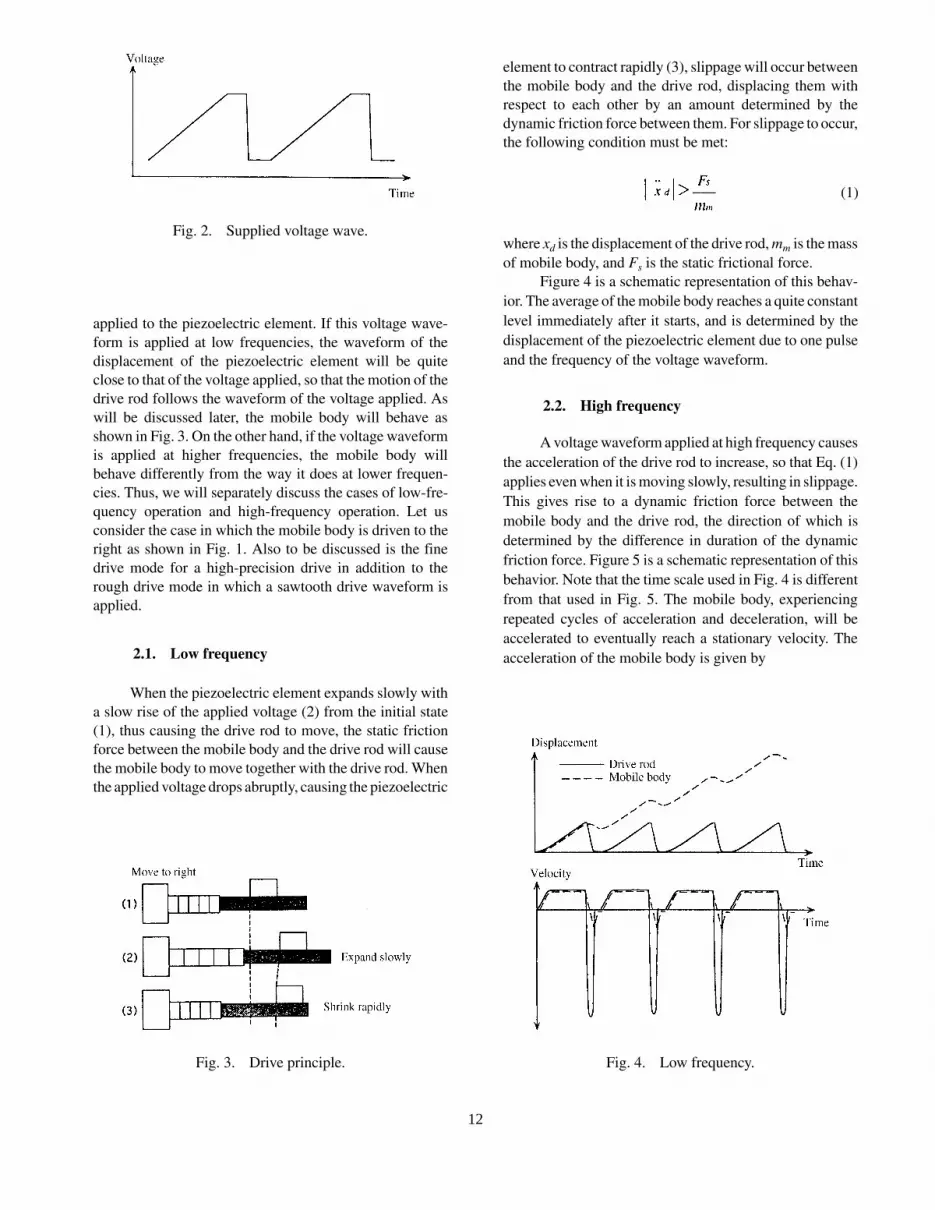
When the piezoelectric element expands slowly with
a slow rise of the applied voltage (2) from the initial state
(1), thus causing the drive rod to move, the static friction
force between the mobile body and the drive rod will cause
the mobile body to move together with the drive rod. When
the applied voltage drops abruptly, causing the piezoelectric
element to contract rapidly (3), slippage will occur between
the mobile body and the drive rod, displacing them with
respect to each other by an amount determined by the
dynamic friction force between them. For slippage to occur,
the following condition must be met:
where xd is the displacement of the drive rod, mm is the mass
of mobile body, and Fs is the static frictional force.
Figure 4 is a schematic representation of this behav-
ior. The average of the mobile body reaches a quite constant
level immediately after it starts, and is determined by the
displacement of the piezoelectric element due to one pulse
and the frequency of the voltage waveform.
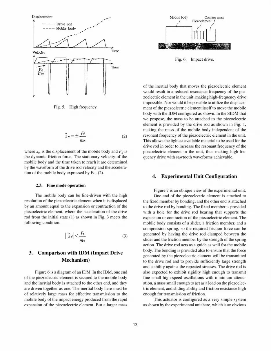
2.2. High frequency
A voltage waveform applied at high frequency causes
the acceleration of the drive rod to increase, so that Eq. (1)
applies even when it is moving slowly, resulting in slippage.
This gives rise to a dynamic friction force between the
mobile body and the drive rod, the direction of which is
determined by the difference in duration of the dynamic
friction force. Figure 5 is a schematic representation of this
behavior. Note that the time scale used in Fig. 4 is different
from that used in Fig. 5. The mobile body, experiencing
repeated cycles of acceleration and deceleration, will be
accelerated to eventually reach a stationary velocity. The
acceleration of the mobile body is given by
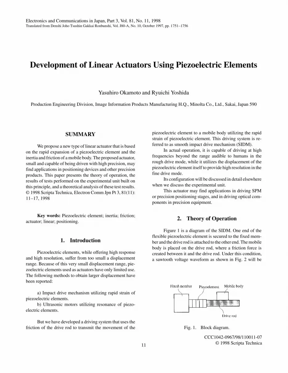
Fig. 2. Supplied voltage wave.
Fig. 3. Drive principle.
(1)
Fig. 4. Low frequency.
12
where xm is the displacement of the mobile body and Fd is
the dynamic friction force. The stationary velocity of the
mobile body and the time taken to reach it are determined
by the waveform of the drive rod velocity and the accelera-
tion of the mobile body expressed by Eq. (2).
2.3. Fine mode operation
The mobile body can be fine-driven with the high
resolution of the piezoelectric element when it is displaced
by an amount equal to the expansion or contraction of the
piezoelectric element, where the acceleration of the drive
rod from the initial state (1) as shown in Fig. 3 meets the
following condition:
3. Comparison with IDM (Impact Drive
Mechanism)
Figure 6 is a diagram of an IDM. In the IDM, one end
of the piezoelectric element is secured to the mobile body
and the inertial body is attached to the other end, and they
are driven together as one. The inertial body here must be
of relatively large mass for effective transmission to the
mobile body of the impact energy produced from the rapid
expansion of the piezoelectric element. But a larger mass
of the inertial body that moves the piezoelectric element
would result in a reduced resonance frequency of the pie-
zoelectric element in the unit, making high-frequency drive
impossible. Nor would it be possible to utilize the displace-
ment of the piezoelectric element itself to move the mobile
body with the IDM configured as shown. In the SIDM that
we propose, the mass to be attached to the piezoelectric
element is provided by the drive rod as shown in Fig. 1,
making the mass of the mobile body independent of the
resonant frequency of the piezoelectric element in the unit.
This allows the lightest available material to be used for the
drive rod in order to increase the resonant frequency of the
piezoelectric element in the unit, thus making high-fre-
quency drive with sawtooth waveforms achievable.
4. Experimental Unit Configuration
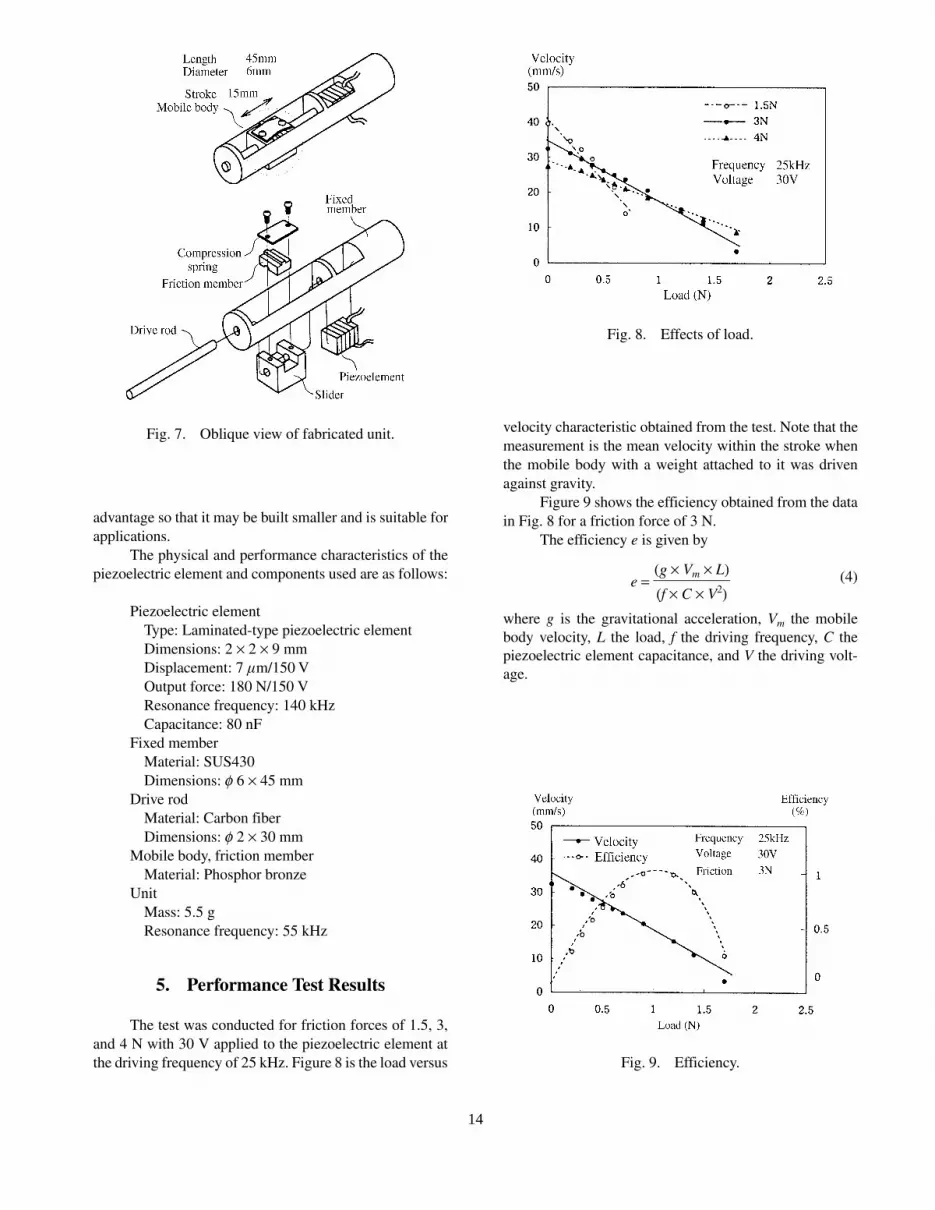
Figure 7 is an oblique view of the experimental unit.
One end of the piezoelectric element is attached to
the fixed member by bonding, and the other end is attached
to the drive rod by bonding. The fixed member is provided
with a hole for the drive rod bearing that supports the
expansion or contraction of the piezoelectric element. The
mobile body consists of a slider, a friction member, and a
compression spring, so the required friction force can be
generated by having the drive rod clamped between the
slider and the friction member by the strength of the spring
action. The drive rod acts as a guide as well for the mobile
body. The bonding is provided also to ensure that the force
generated by the piezoelectric element will be transmitted
to the drive rod and to provide sufficiently large strength
and stability against the repeated stresses. The drive rod is
also expected to exhibit rigidity high enough to transmit
fine small high-speed oscillations with minimum attenu-
ation, a mass small enough to act as a load on the piezoelec-
tric element, and sliding ability and friction resistance high
enough for transmission of friction.
This actuator is configured as a very simple system
as shown by the experimental unit here, which is an obvious
(3)
(2)
Fig. 5. High frequency.
Fig. 6. Impact drive.
13
advantage so that it may be built smaller and is suitable for
applications.
The physical and performance characteristics of the
piezoelectric element and components used are as follows:
Piezoelectric element
Type: Laminated-type piezoelectric element
Dimensions: 2 ´ 2 ´ 9 mm
Displacement: 7 mm/150 V
Output force: 180 N/150 V
Resonance frequency: 140 kHz
Capacitance: 80 nF
Fixed member
Material: SUS430
Dimensions: f 6 ´ 45 mm
Drive rod
Material: Carbon fiber
Dimensions: f 2 ´ 30 mm
Mobile body, friction member
Material: Phosphor bronze
Unit
Mass: 5.5 g
Resonance frequency: 55 kHz
5. Performance Test Results
The test was conducted for friction forces of 1.5, 3,
and 4 N with 30 V applied to the piezoelectric element at
the driving frequency of 25 kHz. Figure 8 is the load versus
velocity characteristic obtained from the test. Note that the
measurement is the mean velocity within the stroke when
the mobile body with a weight attached to it was driven
against gravity.
Figure 9 shows the efficiency obtained from the data
in Fig. 8 for a friction force of 3 N.
The efficiency e is given by
(4)e = (g ´ Vm ´ L)
(f ´ C ´ V2)
where g is the gravitational acceleration, Vm the mobile
body velocity, L the load, f the driving frequency, C the
piezoelectric element capacitance, and V the driving volt-
age.
Fig. 7. Oblique view of fabricated unit.
Fig. 8. Effects of load.
Fig. 9. Efficiency.
14
6. Analysis
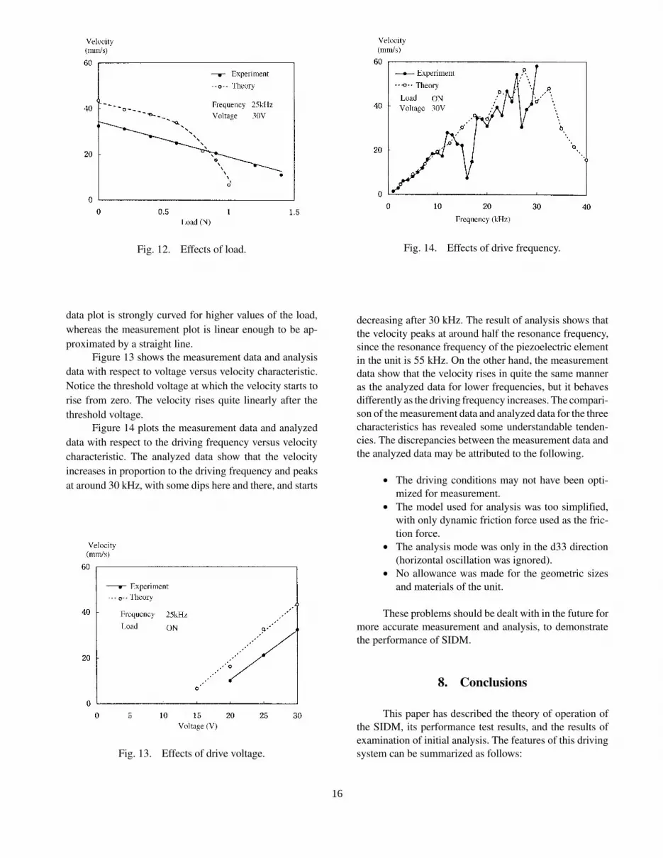
Figure 10(a) is a mechanical model of the actuator.
The electronic circuit model shown in (b), which is equiva-
lent to this mechanical model, was analyzed with an elec-
tronic circuit simulator (P-SPICE). In this model, a
distribution constant circuit was used as equivalent to the
drive rod. Two ideal zener diodes placed end to end were
used as an equivalent to friction. It is for this reason that the
model has only the dynamic friction force represented. The
analysis parameters are listed in Fig. 10. Of these parame-
ters, such piezoelectric element parameters as A, Cp, rp, and
Lp were obtained from the impedance analyzer test results.
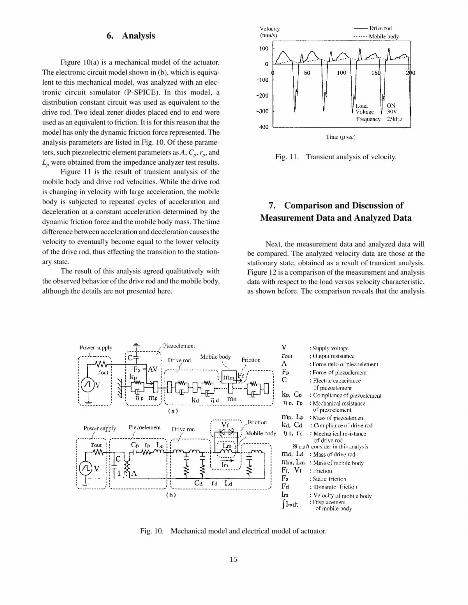
Figure 11 is the result of transient analysis of the
mobile body and drive rod velocities. While the drive rod
is changing in velocity with large acceleration, the mobile
body is subjected to repeated cycles of acceleration and
deceleration at a constant acceleration determined by the
dynamic friction force and the mobile body mass. The time
difference between acceleration and deceleration causes the
velocity to eventually become equal to the lower velocity
of the drive rod, thus effecting the transition to the station-
ary state.
The result of this analysis agreed qualitatively with
the observed behavior of the drive rod and the mobile body,
although the details are not presented here.
7. Comparison and Discussion of
Measurement Data and Analyzed Data
Next, the measurement data and analyzed data will
be compared. The analyzed velocity data are those at the
stationary state, obtained as a result of transient analysis.
Figure 12 is a comparison of the measurement and analysis
data with respect to the load versus velocity characteristic,
as shown before. The comparison reveals that the analysis
Fig. 10. Mechanical model and electrical model of actuator.
Fig. 11. Transient analysis of velocity.
15
data plot is strongly curved for higher values of the load,
whereas the measurement plot is linear enough to be ap-
proximated by a straight line.
Figure 13 shows the measurement data and analysis
data with respect to voltage versus velocity characteristic.
Notice the threshold voltage at which the velocity starts to
rise from zero. The velocity rises quite linearly after the
threshold voltage.
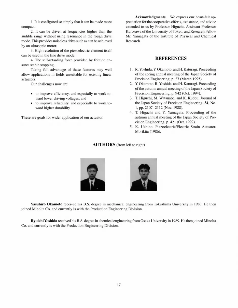
Figure 14 plots the measurement data and analyzed
data with respect to the driving frequency versus velocity
characteristic. The analyzed data show that the velocity
increases in proportion to the driving frequency and peaks
at around 30 kHz, with some dips here and there, and starts
decreasing after 30 kHz. The result of analysis shows that
the velocity peaks at around half the resonance frequency,
since the resonance frequency of the piezoelectric element
in the unit is 55 kHz. On the other hand, the measurement
data show that the velocity rises in quite the same manner
as the analyzed data for lower frequencies, but it behaves
differently as the driving frequency increases. The compari-
son of the measurement data and analyzed data for the three
characteristics has revealed some understandable tenden-
cies. The discrepancies between the measurement data and
the analyzed data may be attributed to the following.
· The driving conditions may not have been opti-
mized for measurement.
· The model used for analysis was too simplified,
with only dynamic friction force used as the fric-
tion force.
· The analysis mode was only in the d33 direction
(horizontal oscillation was ignored).
· No allowance was made for the geometric sizes
and materials of the unit.
These problems should be dealt with in the future for
more accurate measurement and analysis, to demonstrate
the performance of SIDM.
8. Conclusions
This paper has described the theory of operation of
the SIDM, its performance test results, and the results of
examination of initial analysis. The features of this driving
system can be summarized as follows:
Fig. 12. Effects of load.
Fig. 13. Effects of drive voltage.
Fig. 14. Effects of drive frequency.
16
1. It is configured so simply that it can be made more
compact.
2. It can be driven at frequencies higher than the
audible range without using resonance in the rough drive
mode. This provides noiseless drive such as can be achieved
by an ultrasonic motor.
3. High resolution of the piezoelectric element itself
can be used in the fine drive mode.
4. The self-retarding force provided by friction en-
sures stable stopping.
Taking full advantage of these features may well
allow applications in fields unsuitable for existing linear
actuators.
Our challenges now are:
· to improve efficiency, and especially to work to-
ward lower driving voltages, and
· to improve reliability, and especially to work to-
ward higher durability.
These are goals for wider application of our actuator.
Acknowledgments. We express our heart-felt ap-
preciation for the cooperative efforts, assistance, and advice
extended to us by Professor Higuchi, Assistant Professor
Kurosawa of the University of Tokyo, and Research Fellow
Mr. Yamagata of the Institute of Physical and Chemical
Research.
REFERENCES
1. R. Yoshida, Y. Okamoto, and H. Katuragi. Proceeding
of the spring annual meeting of the Japan Society of
Precision Engineering, p. 27 (March 1995).
2. Y. Okamoto, R. Yoshida, and H. Katuragi. Proceeding
of the autumn annual meeting of the Japan Society of
Precision Engineering, p. 942 (Oct. 1994).
3. T. Higuchi, M. Watanabe, and K. Kudou. Journal of
the Japan Society of Precision Engineering, 54, No.
1, pp. 2107�2112 (Nov. 1988).
4. T. Higachi and Y. Yamagata. Proceeding of the
autumn annual meeting of the Japan Society of Pre-
cision Engineering, p. 421 (Oct. 1992).
5. K. Uchino. Piezoelectric/Electric Strain Actuator.
Morikita (1986).
AUTHORS (from left to right)
Yasuhiro Okamoto received his B.S. degree in mechanical engineering from Tokushima University in 1983. He then
joined Minolta Co. and currently is with the Production Engineering Division.
Ryuichi Yoshida received his B.S. degree in chemical engineering from Osaka University in 1989. He then joined Minolta
Co. and currently is with the Production Engineering Division.