Energy Flow Analysis in Piezoelectric EnergyHarvesting Systems
KENJI UCHINO1,∗,∗∗ AND TAKAAKI ISHII2
1International Center for Actuators and Transducers, Materials ResearchInstitute, The Pennsylvania State University, University Park, PA 16802, USA2Department of Research Interdisciplinary, Graduate School of Medicine andEngineering Information System Engineering, University of Yamanashi, 4-4-37Takeda, Kofu-Shi, Yamanashi 400-8510, Japan
Energy recovery from wasted or unused power has been the topic of discussion for a longtime. In recent years, industrial and academic research units have focused on harvestingenergy from mechanical vibrations using piezoelectric transducers. These efforts haveprovided the initial research guidelines and have brought in light the problems and limi-tations of implementing the piezoelectric transducer. There are three major phases/stepsassociated with piezoelectric energy harvesting: (i) mechanical-mechanical energytransfer, including mechanical stability of the piezoelectric transducer under largestresses, and mechanical impedance matching, (ii) mechanical-electrical energy trans-duction, relating with the electromechanical coupling factor in the composite transducerstructure, and (iii) electrical-electrical energy transfer, including electrical impedancematching, such as a DC/DC converter to accumulate the energy into a rechargeablebattery. This paper deals with detailed energy flow analysis in piezoelectric energyharvesting systems with typical stiff “Cymbals” and flexible piezoelectric transducers,in order to provide comprehensive strategies on how to improve the efficiency of theharvesting system. Energy transfer rates are practically evaluated in the above all steps.
Keywords Piezoelectric material; transducer; energy harvesting; energy transfer;impedance matching; electromechanical coupling factor.
1. Background
Energy recovery from wasted or unused power has been the topic of discussion for along time. Unused power exists in various mechanical forms such as ambient vibrations,water flow, wind, human motion and shock waves. In recent years, industrial and aca-demic research units have focused their attention on harvesting energy from vibrationsusing piezoelectric transducers. These efforts have provided the initial research guidelinesand have brought light to the problems and limitations of implementing the piezoelectrictransducer [1].
Received in final form July 21, 2009.∗Corresponding author. E-mail: [email protected]
∗∗Affiliated also with Office of Naval Research, ONR Global-Asia, Roppongi, Minao-Ku, Tokyo,
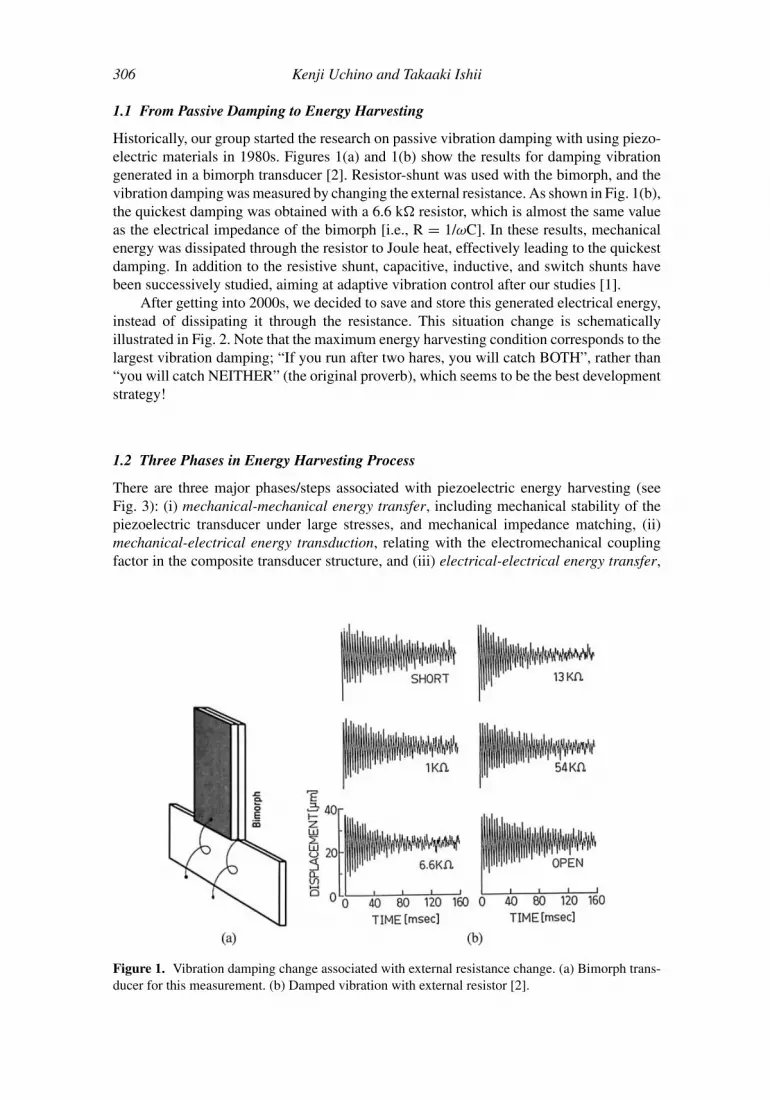
Historically, our group started the research on passive vibration damping with using piezo-electric materials in 1980s. Figures 1(a) and 1(b) show the results for damping vibrationgenerated in a bimorph transducer [2]. Resistor-shunt was used with the bimorph, and thevibration damping was measured by changing the external resistance. As shown in Fig. 1(b),the quickest damping was obtained with a 6.6 k resistor, which is almost the same valueas the electrical impedance of the bimorph [i.e., R = 1/ωC]. In these results, mechanicalenergy was dissipated through the resistor to Joule heat, effectively leading to the quickestdamping. In addition to the resistive shunt, capacitive, inductive, and switch shunts havebeen successively studied, aiming at adaptive vibration control after our studies [1].
After getting into 2000s, we decided to save and store this generated electrical energy,instead of dissipating it through the resistance. This situation change is schematicallyillustrated in Fig. 2. Note that the maximum energy harvesting condition corresponds to thelargest vibration damping; “If you run after two hares, you will catch BOTH”, rather than“you will catch NEITHER” (the original proverb), which seems to be the best developmentstrategy!
1.2 Three Phases in Energy Harvesting Process
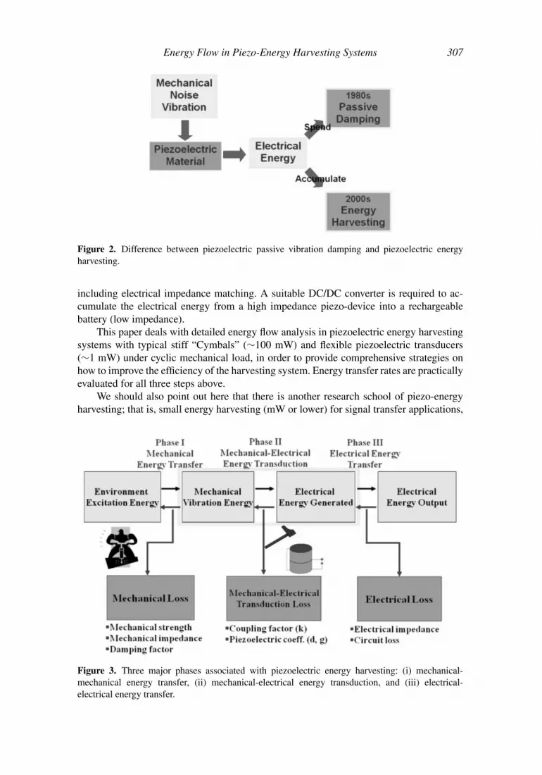
There are three major phases/steps associated with piezoelectric energy harvesting (seeFig. 3): (i) mechanical-mechanical energy transfer, including mechanical stability of thepiezoelectric transducer under large stresses, and mechanical impedance matching, (ii)mechanical-electrical energy transduction, relating with the electromechanical couplingfactor in the composite transducer structure, and (iii) electrical-electrical energy transfer,
Figure 1. Vibration damping change associated with external resistance change. (a) Bimorph trans-ducer for this measurement. (b) Damped vibration with external resistor [2].
Energy Flow in Piezo-Energy Harvesting Systems 307
Figure 2. Difference between piezoelectric passive vibration damping and piezoelectric energyharvesting.
including electrical impedance matching. A suitable DC/DC converter is required to ac-cumulate the electrical energy from a high impedance piezo-device into a rechargeablebattery (low impedance).
This paper deals with detailed energy flow analysis in piezoelectric energy harvestingsystems with typical stiff “Cymbals” (∼100 mW) and flexible piezoelectric transducers(∼1 mW) under cyclic mechanical load, in order to provide comprehensive strategies onhow to improve the efficiency of the harvesting system. Energy transfer rates are practicallyevaluated for all three steps above.
We should also point out here that there is another research school of piezo-energyharvesting; that is, small energy harvesting (mW or lower) for signal transfer applications,
Figure 3. Three major phases associated with piezoelectric energy harvesting: (i) mechanical-mechanical energy transfer, (ii) mechanical-electrical energy transduction, and (iii) electrical-electrical energy transfer.
308 Kenji Uchino and Takaaki Ishii
where the efficiency is not a primary objective. This school usually treats a burst/pulseload to generate instantaneous electric energy for transmitting signals for a short period(100 ms—10 s), without accumulating the electricity in a rechargeable battery. Successfulproducts (million sellers) in the commercial market belong mostly to this category atpresent, including “Lightning Switch [3]” [remote switch for room lights, with using aunimorph piezoelectric component] by PulseSwitch Systems, VA, and the 25 mm caliber“Programmable Ammunition [4]” [electricity generation with a multilayer piezo-actuatorunder shot impact] by ATK Integrated Weapon Systems, AZ.
2. Mechanical-to-Mechanical Energy Transfer
First of all, wasted or unused mechanical energy (vibration source) should be transferredproperly to the energy converter such as piezoelectric devices. Mechanical impedancematching is one of the important factors we have to take into account. The mechanicalimpedance of the material is defined by
Z = (ρc)1/2, (1)
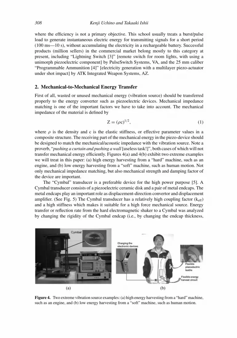
where ρ is the density and c is the elastic stiffness, or effective parameter values in acomposite structure. The receiving part of the mechanical energy in the piezo-device shouldbe designed to match the mechanical/acoustic impedance with the vibration source. Note aproverb, “pushing a curtain and pushing a wall [useless task!]”, both cases of which will nottransfer mechanical energy efficiently. Figures 4(a) and 4(b) exhibit two extreme exampleswe will treat in this paper: (a) high energy harvesting from a “hard” machine, such as anengine, and (b) low energy harvesting from a “soft” machine, such as human motion. Notonly mechanical impedance matching, but also mechanical strength and damping factor ofthe device are important.
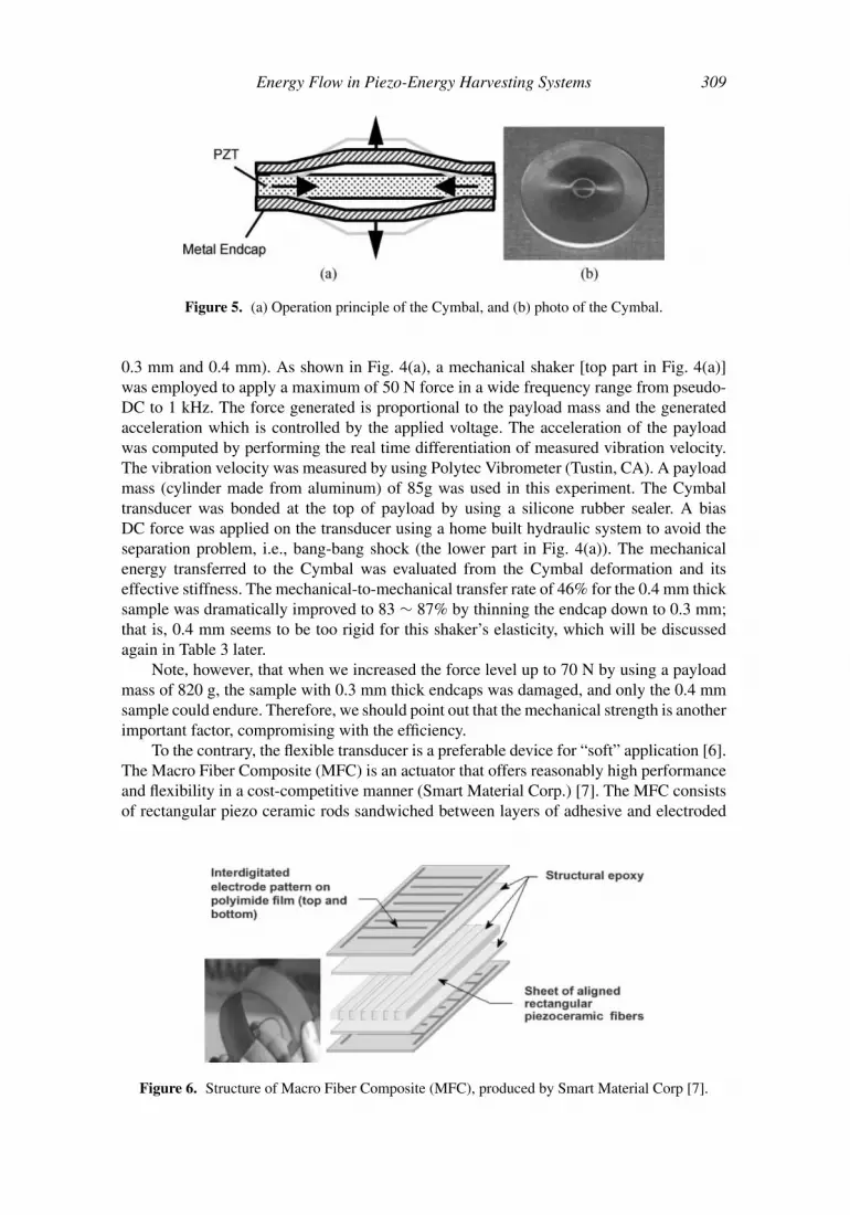
The “Cymbal” transducer is a preferable device for the high power purpose [5]. ACymbal transducer consists of a piezoelectric ceramic disk and a pair of metal endcaps. Themetal endcaps play an important role as displacement-direction convertor and displacementamplifier. (See Fig. 5) The Cymbal transducer has a relatively high coupling factor (keff)and a high stiffness which makes it suitable for a high force mechanical source. Energytransfer or reflection rate from the hard electromagnetic shaker to a Cymbal was analyzedby changing the rigidity of the Cymbal endcap (i.e., by changing the endcap thickness,
Figure 4. Two extreme vibration source examples: (a) high energy harvesting from a “hard” machine,such as an engine, and (b) low energy harvesting from a “soft” machine, such as human motion.
Energy Flow in Piezo-Energy Harvesting Systems 309
Figure 5. (a) Operation principle of the Cymbal, and (b) photo of the Cymbal.
0.3 mm and 0.4 mm). As shown in Fig. 4(a), a mechanical shaker [top part in Fig. 4(a)]was employed to apply a maximum of 50 N force in a wide frequency range from pseudo-DC to 1 kHz. The force generated is proportional to the payload mass and the generatedacceleration which is controlled by the applied voltage. The acceleration of the payloadwas computed by performing the real time differentiation of measured vibration velocity.The vibration velocity was measured by using Polytec Vibrometer (Tustin, CA). A payloadmass (cylinder made from aluminum) of 85g was used in this experiment. The Cymbaltransducer was bonded at the top of payload by using a silicone rubber sealer. A biasDC force was applied on the transducer using a home built hydraulic system to avoid theseparation problem, i.e., bang-bang shock (the lower part in Fig. 4(a)). The mechanicalenergy transferred to the Cymbal was evaluated from the Cymbal deformation and itseffective stiffness. The mechanical-to-mechanical transfer rate of 46% for the 0.4 mm thicksample was dramatically improved to 83 ∼ 87% by thinning the endcap down to 0.3 mm;that is, 0.4 mm seems to be too rigid for this shaker’s elasticity, which will be discussedagain in Table 3 later.
Note, however, that when we increased the force level up to 70 N by using a payloadmass of 820 g, the sample with 0.3 mm thick endcaps was damaged, and only the 0.4 mmsample could endure. Therefore, we should point out that the mechanical strength is anotherimportant factor, compromising with the efficiency.
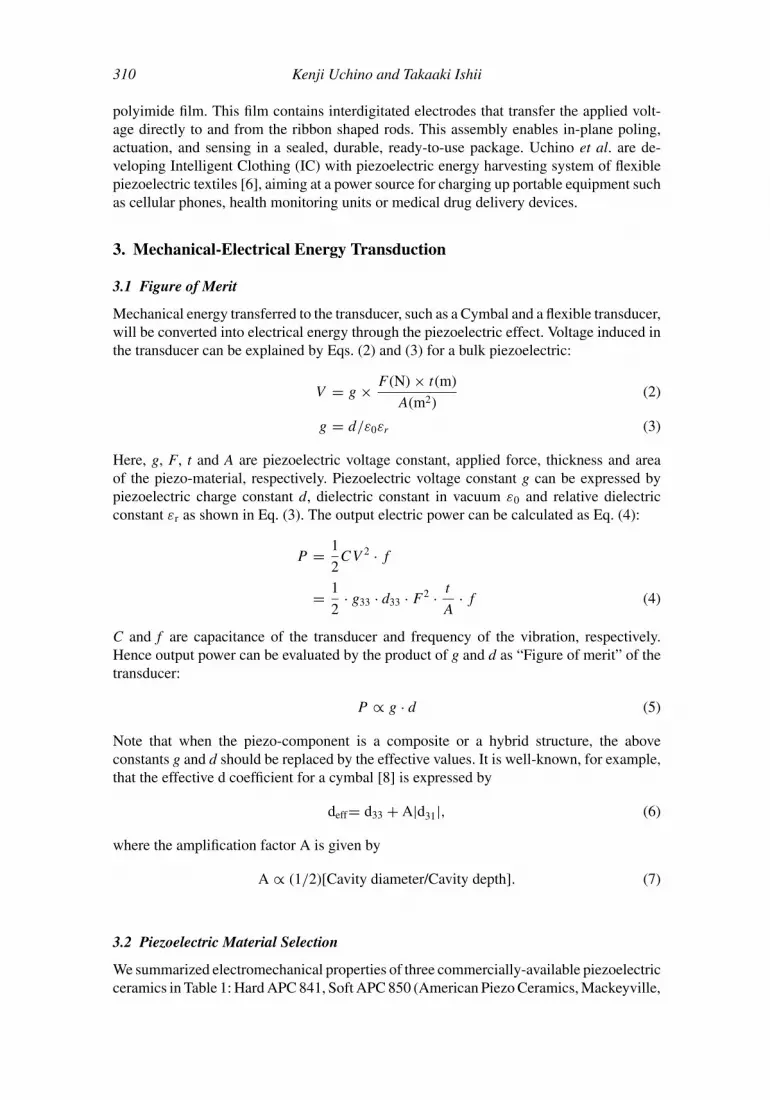
To the contrary, the flexible transducer is a preferable device for “soft” application [6].The Macro Fiber Composite (MFC) is an actuator that offers reasonably high performanceand flexibility in a cost-competitive manner (Smart Material Corp.) [7]. The MFC consistsof rectangular piezo ceramic rods sandwiched between layers of adhesive and electroded
Figure 6. Structure of Macro Fiber Composite (MFC), produced by Smart Material Corp [7].
310 Kenji Uchino and Takaaki Ishii
polyimide film. This film contains interdigitated electrodes that transfer the applied volt-age directly to and from the ribbon shaped rods. This assembly enables in-plane poling,actuation, and sensing in a sealed, durable, ready-to-use package. Uchino et al. are de-veloping Intelligent Clothing (IC) with piezoelectric energy harvesting system of flexiblepiezoelectric textiles [6], aiming at a power source for charging up portable equipment suchas cellular phones, health monitoring units or medical drug delivery devices.
3. Mechanical-Electrical Energy Transduction
3.1 Figure of Merit
Mechanical energy transferred to the transducer, such as a Cymbal and a flexible transducer,will be converted into electrical energy through the piezoelectric effect. Voltage induced inthe transducer can be explained by Eqs. (2) and (3) for a bulk piezoelectric:
V = g × F (N) × t(m)
A(m2)(2)
g = d/ε0εr (3)
Here, g, F, t and A are piezoelectric voltage constant, applied force, thickness and areaof the piezo-material, respectively. Piezoelectric voltage constant g can be expressed bypiezoelectric charge constant d, dielectric constant in vacuum ε0 and relative dielectricconstant εr as shown in Eq. (3). The output electric power can be calculated as Eq. (4):
P = 1
2CV 2 · f
= 1
2· g33 · d33 · F 2 · t
A· f (4)
C and f are capacitance of the transducer and frequency of the vibration, respectively.Hence output power can be evaluated by the product of g and d as “Figure of merit” of thetransducer:
P ∝ g · d (5)
Note that when the piezo-component is a composite or a hybrid structure, the aboveconstants g and d should be replaced by the effective values. It is well-known, for example,that the effective d coefficient for a cymbal [8] is expressed by
deff= d33 + A|d31|, (6)
where the amplification factor A is given by
A ∝ (1/2)[Cavity diameter/Cavity depth]. (7)
3.2 Piezoelectric Material Selection
We summarized electromechanical properties of three commercially-available piezoelectricceramics in Table 1: Hard APC 841, Soft APC 850 (American Piezo Ceramics, Mackeyville,
Energy Flow in Piezo-Energy Harvesting Systems 311
Table 1Electromechanical properties of the commercially-available piezoelectric ceramics
Hard Soft High gParameter (APC 841) (APC 850) (D210)
PA), and High g D210 (Dong Il Technology, Korea). We can find the best material (D210)for the energy harvesting application easily by comparing g·d product values.
3.3 Design Optimization
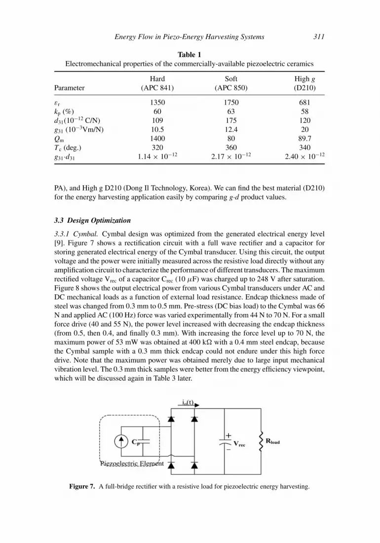
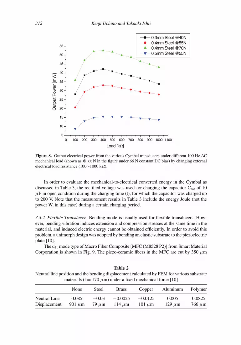
3.3.1 Cymbal. Cymbal design was optimized from the generated electrical energy level[9]. Figure 7 shows a rectification circuit with a full wave rectifier and a capacitor forstoring generated electrical energy of the Cymbal transducer. Using this circuit, the outputvoltage and the power were initially measured across the resistive load directly without anyamplification circuit to characterize the performance of different transducers. The maximumrectified voltage Vrec of a capacitor Crec (10 µF) was charged up to 248 V after saturation.Figure 8 shows the output electrical power from various Cymbal transducers under AC andDC mechanical loads as a function of external load resistance. Endcap thickness made ofsteel was changed from 0.3 mm to 0.5 mm. Pre-stress (DC bias load) to the Cymbal was 66N and applied AC (100 Hz) force was varied experimentally from 44 N to 70 N. For a smallforce drive (40 and 55 N), the power level increased with decreasing the endcap thickness(from 0.5, then 0.4, and finally 0.3 mm). With increasing the force level up to 70 N, themaximum power of 53 mW was obtained at 400 k with a 0.4 mm steel endcap, becausethe Cymbal sample with a 0.3 mm thick endcap could not endure under this high forcedrive. Note that the maximum power was obtained merely due to large input mechanicalvibration level. The 0.3 mm thick samples were better from the energy efficiency viewpoint,which will be discussed again in Table 3 later.
Figure 7. A full-bridge rectifier with a resistive load for piezoelectric energy harvesting.
Figure 8. Output electrical power from the various Cymbal transducers under different 100 Hz ACmechanical load (shown as @ xx N in the figure under 66 N constant DC bias) by changing externalelectrical load resistance (100∼1000 k).
In order to evaluate the mechanical-to-electrical converted energy in the Cymbal asdiscussed in Table 3, the rectified voltage was used for charging the capacitor Crec of 10µF in open condition during the charging time (t), for which the capacitor was charged upto 200 V. Note that the measurement results in Table 3 include the energy Joule (not thepower W, in this case) during a certain charging period.
3.3.2 Flexible Transducer. Bending mode is usually used for flexible transducers. How-ever, bending vibration induces extension and compression stresses at the same time in thematerial, and induced electric energy cannot be obtained efficiently. In order to avoid thisproblem, a unimorph design was adopted by bonding an elastic substrate to the piezoelectricplate [10].
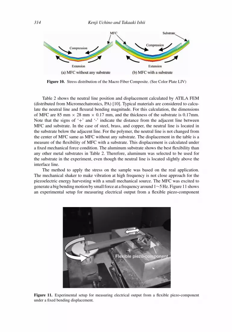
The d31 mode type of Macro Fiber Composite [MFC (M8528 P2)] from Smart MaterialCorporation is shown in Fig. 9. The piezo-ceramic fibers in the MFC are cut by 350 µm
Table 2Neutral line position and the bending displacement calculated by FEM for various substrate
materials (t = 170 µm) under a fixed mechanical force [10]
Energy Flow in Piezo-Energy Harvesting Systems 313
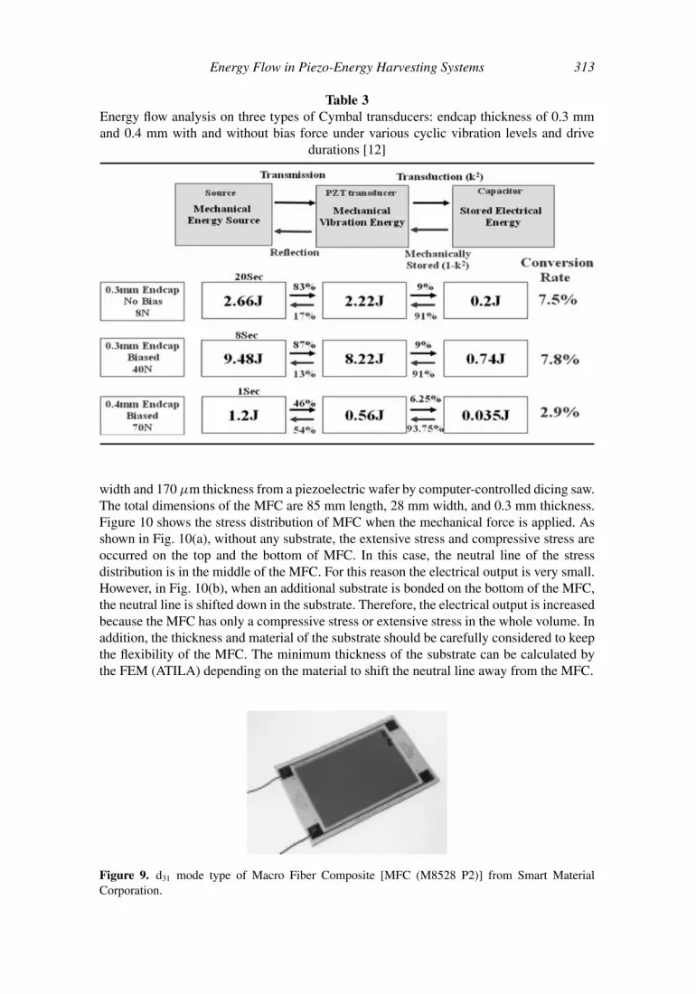
Table 3Energy flow analysis on three types of Cymbal transducers: endcap thickness of 0.3 mmand 0.4 mm with and without bias force under various cyclic vibration levels and drive
durations [12]
width and 170 µm thickness from a piezoelectric wafer by computer-controlled dicing saw.The total dimensions of the MFC are 85 mm length, 28 mm width, and 0.3 mm thickness.Figure 10 shows the stress distribution of MFC when the mechanical force is applied. Asshown in Fig. 10(a), without any substrate, the extensive stress and compressive stress areoccurred on the top and the bottom of MFC. In this case, the neutral line of the stressdistribution is in the middle of the MFC. For this reason the electrical output is very small.However, in Fig. 10(b), when an additional substrate is bonded on the bottom of the MFC,the neutral line is shifted down in the substrate. Therefore, the electrical output is increasedbecause the MFC has only a compressive stress or extensive stress in the whole volume. Inaddition, the thickness and material of the substrate should be carefully considered to keepthe flexibility of the MFC. The minimum thickness of the substrate can be calculated bythe FEM (ATILA) depending on the material to shift the neutral line away from the MFC.
Figure 9. d31 mode type of Macro Fiber Composite [MFC (M8528 P2)] from Smart MaterialCorporation.
314 Kenji Uchino and Takaaki Ishii
Figure 10. Stress distribution of the Macro Fiber Composite. (See Color Plate LIV)
Table 2 shows the neutral line position and displacement calculated by ATILA FEM(distributed from Micromechatronics, PA) [10]. Typical materials are considered to calcu-late the neutral line and flexural bending magnitude. For this calculation, the dimensionsof MFC are 85 mm × 28 mm × 0.17 mm, and the thickness of the substrate is 0.17mm.Note that the signs of ‘+’ and ‘-’ indicate the distance from the adjacent line betweenMFC and substrate. In the case of steel, brass, and copper, the neutral line is located inthe substrate below the adjacent line. For the polymer, the neutral line is not changed fromthe center of MFC same as MFC without any substrate. The displacement in the table is ameasure of the flexibility of MFC with a substrate. This displacement is calculated undera fixed mechanical force condition. The aluminum substrate shows the best flexibility thanany other metal substrates in Table 2. Therefore, aluminum was selected to be used forthe substrate in the experiment, even though the neutral line is located slightly above theinterface line.
The method to apply the stress on the sample was based on the real application.The mechanical shaker to make vibration at high frequency is not close approach for thepiezoelectric energy harvesting with a small mechanical source. The MFC was excited togenerate a big bending motion by small force at a frequency around 1∼5 Hz. Figure 11 showsan experimental setup for measuring electrical output from a flexible piezo-component
Figure 11. Experimental setup for measuring electrical output from a flexible piezo-componentunder a fixed bending displacement.
Energy Flow in Piezo-Energy Harvesting Systems 315
210-1-2-3-60
-40
-20
0
20
40
(a)
Out
put V
olta
ge [V
]
Time [sec]
Without Substrate With Aluminum Substrate
50 100 150 200 250 300 350 400 450 500 55010
12
14
16
18
20
22
24
26
Load [kΩ]
Rec
tifire
d V
olta
ge [v
rec]
1.0
1.2
1.4
1.6
1.8
2.0
(b)
Output P
ower [m
W]
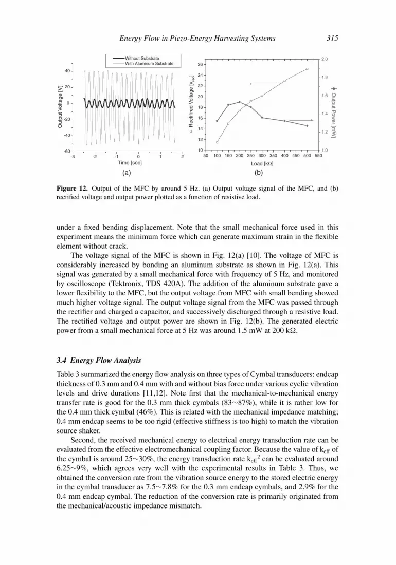
Figure 12. Output of the MFC by around 5 Hz. (a) Output voltage signal of the MFC, and (b)rectified voltage and output power plotted as a function of resistive load.
under a fixed bending displacement. Note that the small mechanical force used in thisexperiment means the minimum force which can generate maximum strain in the flexibleelement without crack.
The voltage signal of the MFC is shown in Fig. 12(a) [10]. The voltage of MFC isconsiderably increased by bonding an aluminum substrate as shown in Fig. 12(a). Thissignal was generated by a small mechanical force with frequency of 5 Hz, and monitoredby oscilloscope (Tektronix, TDS 420A). The addition of the aluminum substrate gave alower flexibility to the MFC, but the output voltage from MFC with small bending showedmuch higher voltage signal. The output voltage signal from the MFC was passed throughthe rectifier and charged a capacitor, and successively discharged through a resistive load.The rectified voltage and output power are shown in Fig. 12(b). The generated electricpower from a small mechanical force at 5 Hz was around 1.5 mW at 200 k.
3.4 Energy Flow Analysis
Table 3 summarized the energy flow analysis on three types of Cymbal transducers: endcapthickness of 0.3 mm and 0.4 mm with and without bias force under various cyclic vibrationlevels and drive durations [11,12]. Note first that the mechanical-to-mechanical energytransfer rate is good for the 0.3 mm thick cymbals (83∼87%), while it is rather low forthe 0.4 mm thick cymbal (46%). This is related with the mechanical impedance matching;0.4 mm endcap seems to be too rigid (effective stiffness is too high) to match the vibrationsource shaker.
Second, the received mechanical energy to electrical energy transduction rate can beevaluated from the effective electromechanical coupling factor. Because the value of keff ofthe cymbal is around 25∼30%, the energy transduction rate keff
2 can be evaluated around6.25∼9%, which agrees very well with the experimental results in Table 3. Thus, weobtained the conversion rate from the vibration source energy to the stored electric energyin the cymbal transducer as 7.5∼7.8% for the 0.3 mm endcap cymbals, and 2.9% for the0.4 mm endcap cymbal. The reduction of the conversion rate is primarily originated fromthe mechanical/acoustic impedance mismatch.
316 Kenji Uchino and Takaaki Ishii
Figure 13. A DC-DC Buck-Converter designed to allow transfer of 43 mW power out of 53 mWfrom the Cymbal (81% efficiency) by converting the original impedance 300 k down to 5 k witha 2% duty cycle and at a switching frequency of 1kHz.
4. Electrical-to-Electrical Energy Transfer
Piezoelectric materials generally convert mechanical energy to electrical energy with rela-tively high voltage which means output impedance is relatively high. On the other hand, en-ergy storage devices such as a rechargeable battery have low input impedance (10∼100).Thus, large portion of the excited electrical energy is reflected back, if we connect the bat-tery immediately after the rectified voltage. In order to improve energy transfer efficiency,electrical impedance matching is required.
4.1 DC-DC Converter
Various converters can step down the voltage to adapt the electrical impedance: Forwardconverter, Buck Converter, Buck-Boost Converter, Flyback Converter etc. These convertershave low output impedance and low loss characteristics. A DC-DC Buck-Converter shownin Fig. 13 was designed to allow transfer of 43 mW power out of 53 mW from the Cymbal(81% efficiency) by converting the original impedance 300 k down to 5 k with a 2%duty cycle and at a switching frequency of 1kHz [11,13].
4.2 Multilayered Cymbal
Since the Buck-Converter introduced in the previous section cannot reduce the outputimpedance sufficiently to match with the rechargeable battery, we should further reducethe output impedance. Output impedance of the transducer can be changed by changing thetransducer structure. Multilayered transducers have low impedance [11]. Figure 14 showscross-sectional view of the multilayered Cymbal transducer. With increasing the number of
Figure 14. Multilayered Cymbal transducer [11].
Energy Flow in Piezo-Energy Harvesting Systems 317
1 10 100 100030
40
50
60
70
80
90
100
Out
put P
ower
[mW
]
Resistive Load [kΩ]
1-layer of 1000µm 2-layer of 500µm 4-layer of 250µm 10-layer of 100µm
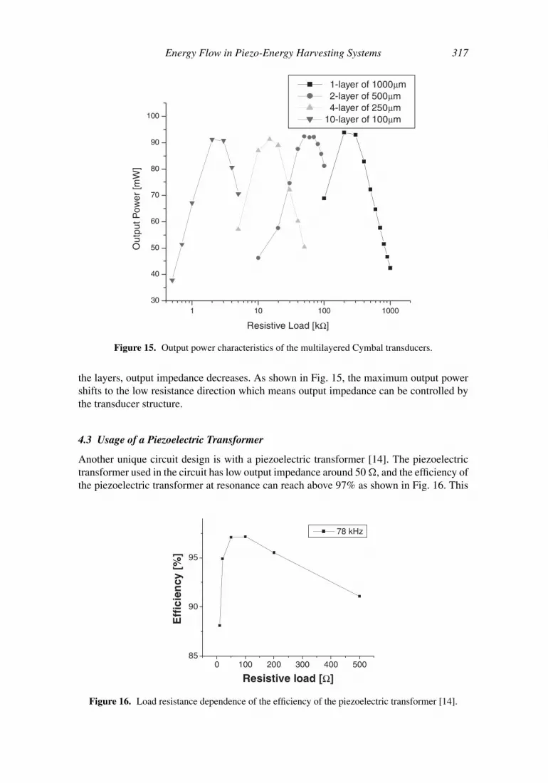
Figure 15. Output power characteristics of the multilayered Cymbal transducers.
the layers, output impedance decreases. As shown in Fig. 15, the maximum output powershifts to the low resistance direction which means output impedance can be controlled bythe transducer structure.
4.3 Usage of a Piezoelectric Transformer
Another unique circuit design is with a piezoelectric transformer [14]. The piezoelectrictransformer used in the circuit has low output impedance around 50 , and the efficiency ofthe piezoelectric transformer at resonance can reach above 97% as shown in Fig. 16. This
0 100 200 300 400 50085
90
95
Eff
icie
ncy
[%
]
Resistive load [Ω]
78 kHz
Figure 16. Load resistance dependence of the efficiency of the piezoelectric transformer [14].
318 Kenji Uchino and Takaaki Ishii
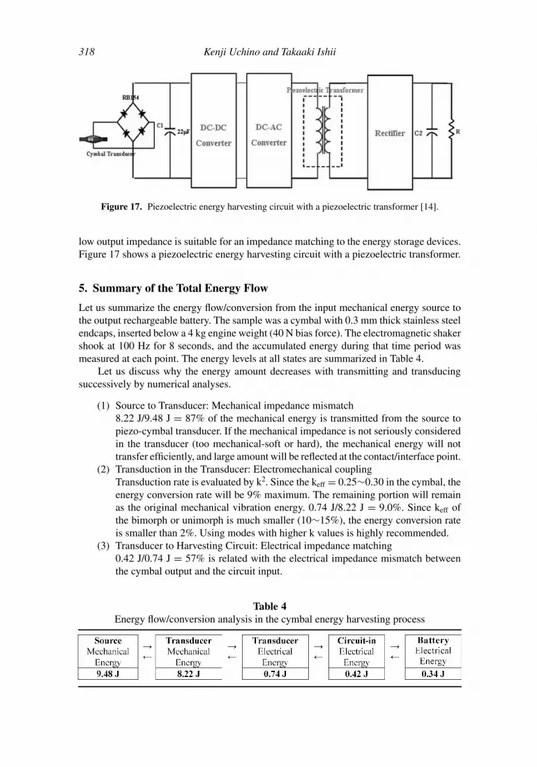
Figure 17. Piezoelectric energy harvesting circuit with a piezoelectric transformer [14].
low output impedance is suitable for an impedance matching to the energy storage devices.Figure 17 shows a piezoelectric energy harvesting circuit with a piezoelectric transformer.
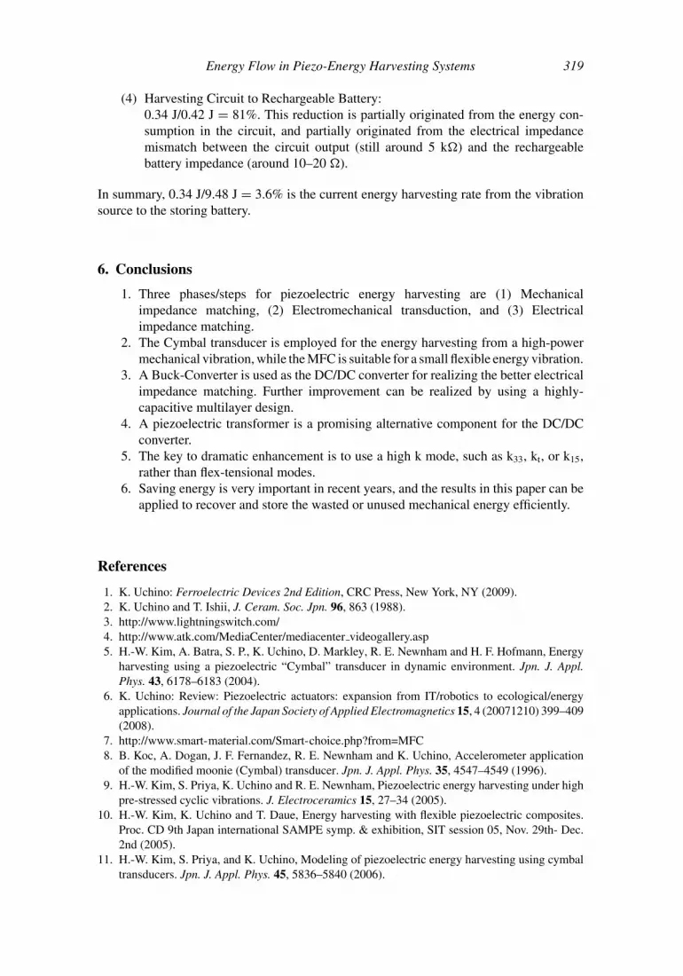
5. Summary of the Total Energy Flow
Let us summarize the energy flow/conversion from the input mechanical energy source tothe output rechargeable battery. The sample was a cymbal with 0.3 mm thick stainless steelendcaps, inserted below a 4 kg engine weight (40 N bias force). The electromagnetic shakershook at 100 Hz for 8 seconds, and the accumulated energy during that time period wasmeasured at each point. The energy levels at all states are summarized in Table 4.
Let us discuss why the energy amount decreases with transmitting and transducingsuccessively by numerical analyses.
(1) Source to Transducer: Mechanical impedance mismatch8.22 J/9.48 J = 87% of the mechanical energy is transmitted from the source topiezo-cymbal transducer. If the mechanical impedance is not seriously consideredin the transducer (too mechanical-soft or hard), the mechanical energy will nottransfer efficiently, and large amount will be reflected at the contact/interface point.
(2) Transduction in the Transducer: Electromechanical couplingTransduction rate is evaluated by k2. Since the keff = 0.25∼0.30 in the cymbal, theenergy conversion rate will be 9% maximum. The remaining portion will remainas the original mechanical vibration energy. 0.74 J/8.22 J = 9.0%. Since keff ofthe bimorph or unimorph is much smaller (10∼15%), the energy conversion rateis smaller than 2%. Using modes with higher k values is highly recommended.
(3) Transducer to Harvesting Circuit: Electrical impedance matching0.42 J/0.74 J = 57% is related with the electrical impedance mismatch betweenthe cymbal output and the circuit input.
Table 4Energy flow/conversion analysis in the cymbal energy harvesting process
Energy Flow in Piezo-Energy Harvesting Systems 319
(4) Harvesting Circuit to Rechargeable Battery:0.34 J/0.42 J = 81%. This reduction is partially originated from the energy con-sumption in the circuit, and partially originated from the electrical impedancemismatch between the circuit output (still around 5 k) and the rechargeablebattery impedance (around 10–20 ).
In summary, 0.34 J/9.48 J = 3.6% is the current energy harvesting rate from the vibrationsource to the storing battery.
6. Conclusions
1. Three phases/steps for piezoelectric energy harvesting are (1) Mechanicalimpedance matching, (2) Electromechanical transduction, and (3) Electricalimpedance matching.
2. The Cymbal transducer is employed for the energy harvesting from a high-powermechanical vibration, while the MFC is suitable for a small flexible energy vibration.
3. A Buck-Converter is used as the DC/DC converter for realizing the better electricalimpedance matching. Further improvement can be realized by using a highly-capacitive multilayer design.
4. A piezoelectric transformer is a promising alternative component for the DC/DCconverter.
5. The key to dramatic enhancement is to use a high k mode, such as k33, kt, or k15,rather than flex-tensional modes.
6. Saving energy is very important in recent years, and the results in this paper can beapplied to recover and store the wasted or unused mechanical energy efficiently.
References
1. K. Uchino: Ferroelectric Devices 2nd Edition, CRC Press, New York, NY (2009).2. K. Uchino and T. Ishii, J. Ceram. Soc. Jpn. 96, 863 (1988).3. http://www.lightningswitch.com/4. http://www.atk.com/MediaCenter/mediacenter videogallery.asp5. H.-W. Kim, A. Batra, S. P., K. Uchino, D. Markley, R. E. Newnham and H. F. Hofmann, Energy
harvesting using a piezoelectric “Cymbal” transducer in dynamic environment. Jpn. J. Appl.Phys. 43, 6178–6183 (2004).
6. K. Uchino: Review: Piezoelectric actuators: expansion from IT/robotics to ecological/energyapplications. Journal of the Japan Society of Applied Electromagnetics 15, 4 (20071210) 399–409(2008).
7. http://www.smart-material.com/Smart-choice.php?from=MFC8. B. Koc, A. Dogan, J. F. Fernandez, R. E. Newnham and K. Uchino, Accelerometer application
of the modified moonie (Cymbal) transducer. Jpn. J. Appl. Phys. 35, 4547–4549 (1996).9. H.-W. Kim, S. Priya, K. Uchino and R. E. Newnham, Piezoelectric energy harvesting under high
pre-stressed cyclic vibrations. J. Electroceramics 15, 27–34 (2005).10. H.-W. Kim, K. Uchino and T. Daue, Energy harvesting with flexible piezoelectric composites.
Proc. CD 9th Japan international SAMPE symp. & exhibition, SIT session 05, Nov. 29th- Dec.2nd (2005).
11. H.-W. Kim, S. Priya, and K. Uchino, Modeling of piezoelectric energy harvesting using cymbaltransducers. Jpn. J. Appl. Phys. 45, 5836–5840 (2006).
320 Kenji Uchino and Takaaki Ishii
12. K. Uchino, Proceedings of 5th Int’l workshop on piezoelectric Mater. & Appl., State College,PA, Oct. 6–10 (2008).
13. H.-W. Kim, S. Priya, H. Stephanau and K. Uchino, IEEE Trans.- UFFC 54 (9), 1851–1859(2007).
14. K. Uchino and A. Vazquez Carazo, Proc. 11th Int’l Conf. New Actuators, Bremen, Germany,June 9–11, 2008, A3.7, 137–140 (2008).