Flow separation in supersonic convergent–divergent nozzleshas been the subject of several experimental and numeri-cal studies in the past. Today, with the renewed interest insupersonic flights and space vehicles, the subject has becomeincreasingly important, especially for aerospace applications(rockets, missiles, supersonic aircrafts, etc.). Flow separationin supersonic nozzles is a basic fluid-dynamics phenomenonthat occurs at a certain pressure ratio of chamber to ambi-ent pressure, resulting in shock formation and shock/tur-bulent-boundary layer interaction inside the nozzle. Frompurely gas-dynamics point of view, this problem involvesbasic structure of shock interactions with separation shock,which consists of incident shock, Mach reflections, reflectedshock, triple point and sliplines (see Figs. 1, 2). Severalviscous phenomena, such as boundary layers with adversepressure gradients, induced separation, recirculation bubbles,shear layers may additionally occur and can strongly affectthe flow-field inside the nozzle (see Figs. 3, 4).
Previous studies on supersonic nozzles [1,2] have shownthat shock-wave/boundary layer interaction (SWBLI) occur-ring in highly overexpanded nozzles may exhibit strongunsteadiness that cause symmetrical or unsymmetrical flowseparation. In rocket design community, shock-induced sep-aration is considered undesirable because an asymmetry inthe flow can yield dangerous lateral forces, the so-called
A. Hadjadj (B)CORIA UMR 6614 CNRS, INSA of Rouen, Site du Madrillet,Av. Université, BP 08, 76800 St Etienne du Rouvray, Francee-mail: [email protected]
M. OnofriDip. Meccanica e Aeronautica, Univ. Roma La Sapienza,Via Eudossiana 18, 00184 Rome, Italye-mail: [email protected]
side-loads, which may damage the nozzle [3]. This phenom-enon has received significant attention in the past and it isstill an active subject of research, whose primarily motivationis to improve nozzle performance under overexpanded flowconditions and to mitigate against nozzle side-loads producedby shock unsteadiness as well as asymmetric boundary-layerseparation.
2 Flow separation in nozzles: a brief literature survey
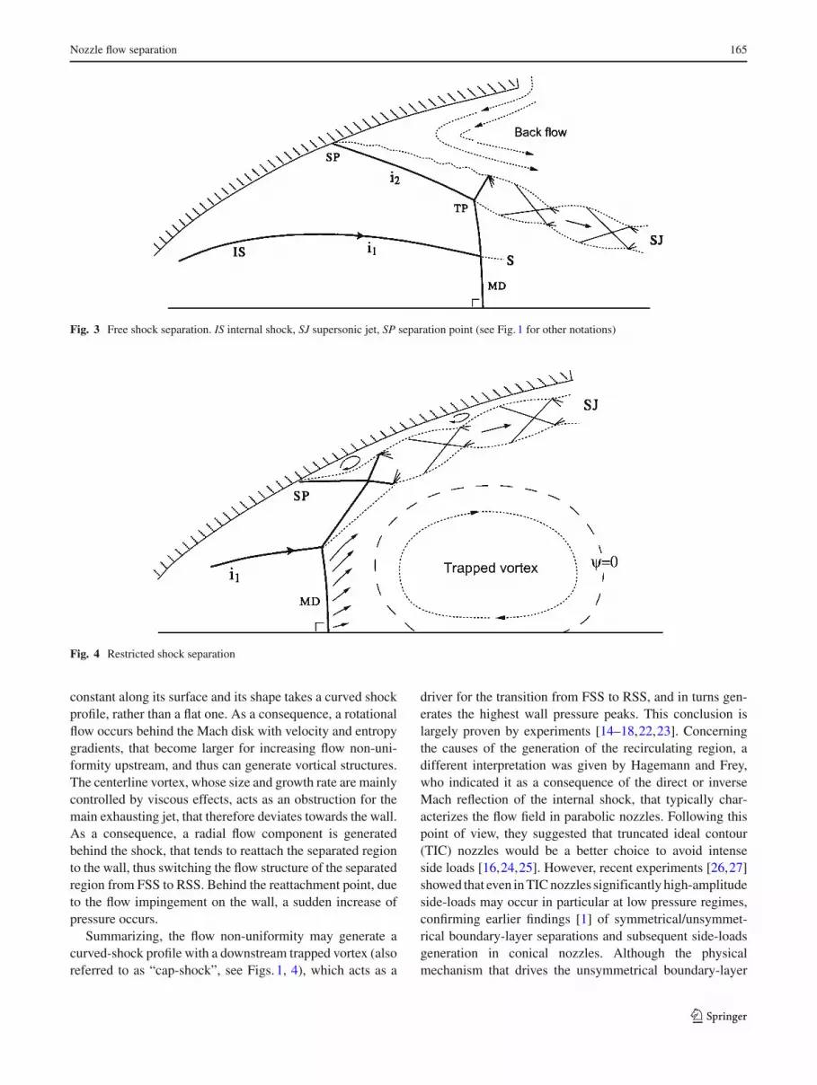
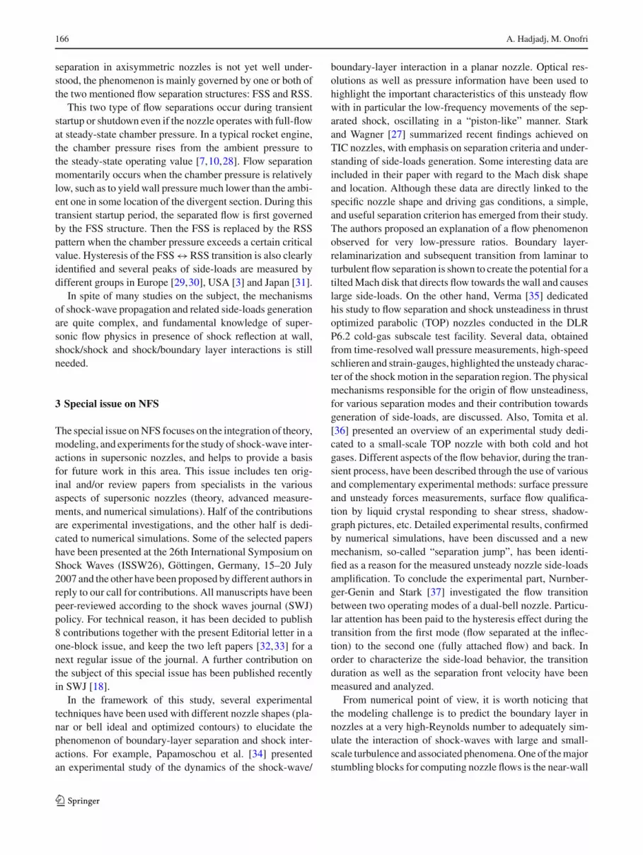
Several experimental studies, performed on either subscale[3–6] or full-scale [3] optimized nozzles, corroborated by dif-ferent numerical simulations [7–11], demonstrated the exis-tence of two distinct separation processes, namely the FreeShock Separation (FSS), in which the boundary layer sepa-rates from the nozzle wall and never reattaches (see Fig. 3),and the restricted shock separation (RSS) characterized bya closed recirculation bubble, downstream of the separationpoint, with reattachment on the wall (see Fig. 4). In fact, theearliest studies attributed the cause of the measured side-loads to asymmetric FSS, that yields a tilted separation sur-face as reported by [3,12]. Subsequently, in the early 70s,during cold-flow subscale tests for the J-2S engine develop-ment, Nave and Coffey [3], in a study that can be consid-ered the pioneer milestone for the field, observed that thehighest value of side loads takes place during the transitionfrom FSS structure to different kind of separated nozzle flowstructures, which had not been noticed before. In particu-lar, the pressure downstream of the separation point showedan unsteady behavior with strong oscillations, and finallyjumped to values quite above the ambient pressure.
They attributed this behavior to the reattachment of theseparated flow to the nozzle wall, and because of the limitedextension of this separated region, they called it restricted
123
164 A. Hadjadj, M. Onofri
2MD
TP1
TP2
2r
1MD
1r
2
S 2
S1
i
1MD
1r
1i
2r
TP
S1
i2r3
S 2
1MD
2r
2MD
1i
1r
1TP
1S
S3
r3
i2 S2
(a) (b) (c)
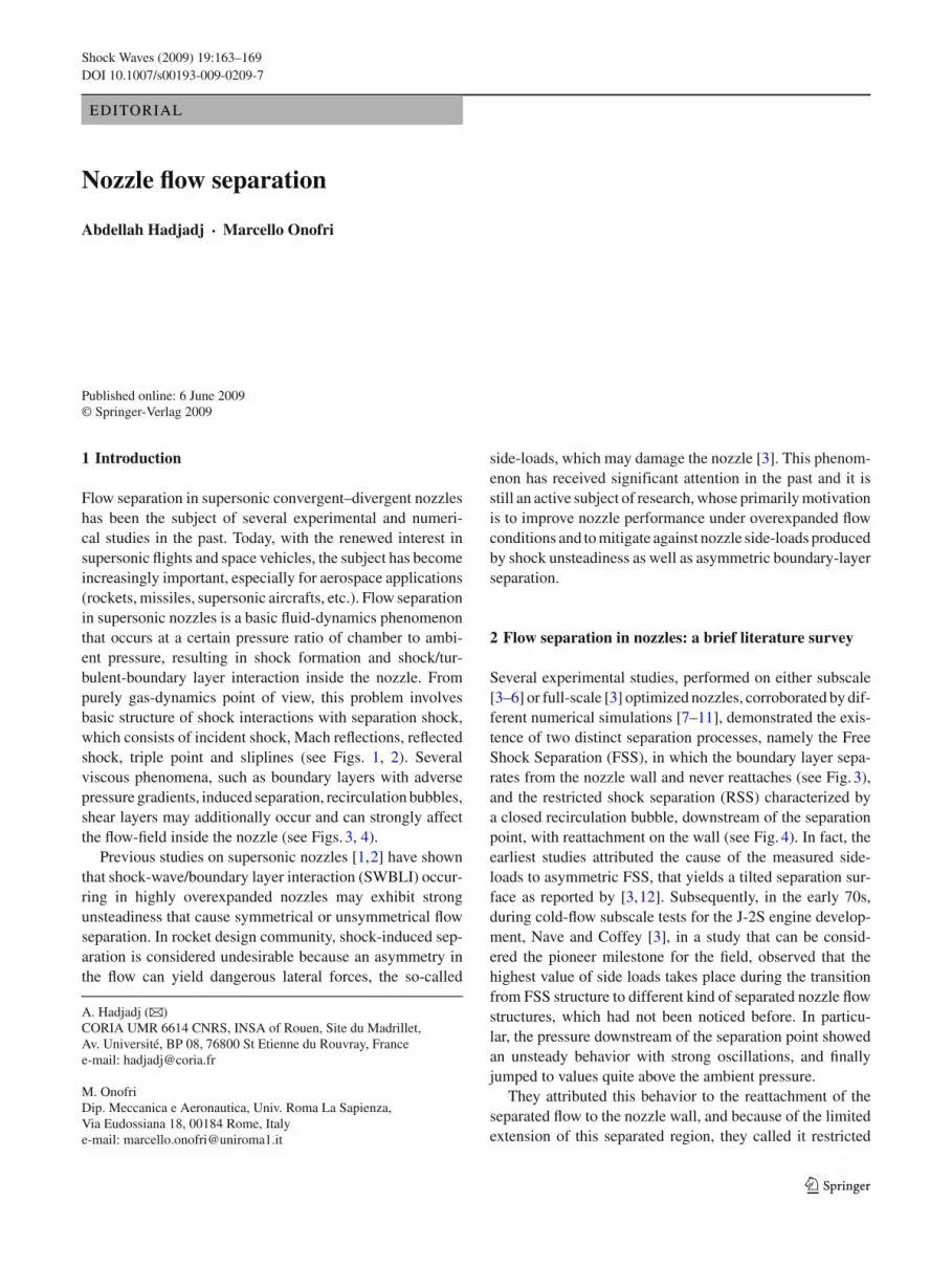
Fig. 1 Schematic illustration of shock interactions and cap-shockpattern in overexpanded supersonic nozzles. Note that, in case a, thecurvature of the Mach disk is due to the upstream flow nonuniformi-ties, characterized by a strong vortical pressure gradient but no inter-nal shock, whereas, in cases b and c, the cap shock pattern is mainlycaused by the impingement of the internal shock with the central Machdisk. The reflected shock resulting from this interaction meets later withthe incident shock (arising from the boundary-layer region) and formeither regular reflection (RR) as in case b or Mach Reflection (MR) as
in case c, depending on their respective slopes. In the latter case, theMR corresponds to an annular Mach disk. Note also that the internalshock is only observed in nozzles with thrust-optimized, parabolic orcompressed contours, and it is induced shortly downstream of the noz-zle throat at the inflection point where wall curvature suddenly changesfrom a convex to a concave contour shape. i1 internal shock, i2 incidentshock, r reflected shock, TP triple point, S slipline, MD1 central Machdisk, MD2 annular Mach disk
2r
1r
1i
MD
TP
i2
S 2
S1
2r
MD
1r1i
i 2
TP
JB
S
(a) (b)
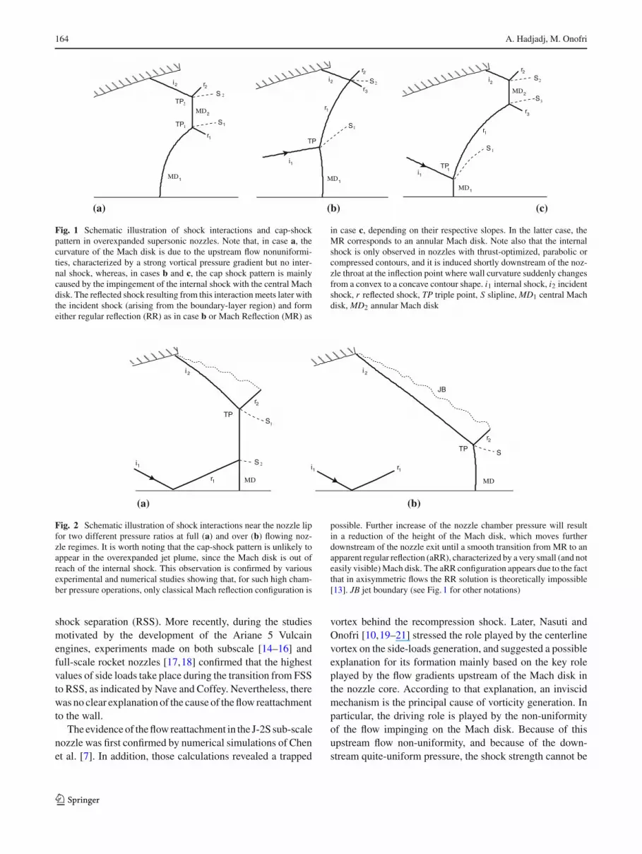
Fig. 2 Schematic illustration of shock interactions near the nozzle lipfor two different pressure ratios at full (a) and over (b) flowing noz-zle regimes. It is worth noting that the cap-shock pattern is unlikely toappear in the overexpanded jet plume, since the Mach disk is out ofreach of the internal shock. This observation is confirmed by variousexperimental and numerical studies showing that, for such high cham-ber pressure operations, only classical Mach reflection configuration is
possible. Further increase of the nozzle chamber pressure will resultin a reduction of the height of the Mach disk, which moves furtherdownstream of the nozzle exit until a smooth transition from MR to anapparent regular reflection (aRR), characterized by a very small (and noteasily visible) Mach disk. The aRR configuration appears due to the factthat in axisymmetric flows the RR solution is theoretically impossible[13]. JB jet boundary (see Fig. 1 for other notations)
shock separation (RSS). More recently, during the studiesmotivated by the development of the Ariane 5 Vulcainengines, experiments made on both subscale [14–16] andfull-scale rocket nozzles [17,18] confirmed that the highestvalues of side loads take place during the transition from FSSto RSS, as indicated by Nave and Coffey. Nevertheless, therewas no clear explanation of the cause of the flow reattachmentto the wall.
The evidence of the flow reattachment in the J-2S sub-scalenozzle was first confirmed by numerical simulations of Chenet al. [7]. In addition, those calculations revealed a trapped
vortex behind the recompression shock. Later, Nasuti andOnofri [10,19–21] stressed the role played by the centerlinevortex on the side-loads generation, and suggested a possibleexplanation for its formation mainly based on the key roleplayed by the flow gradients upstream of the Mach disk inthe nozzle core. According to that explanation, an inviscidmechanism is the principal cause of vorticity generation. Inparticular, the driving role is played by the non-uniformityof the flow impinging on the Mach disk. Because of thisupstream flow non-uniformity, and because of the down-stream quite-uniform pressure, the shock strength cannot be
Fig. 3 Free shock separation. IS internal shock, SJ supersonic jet, SP separation point (see Fig. 1 for other notations)
Fig. 4 Restricted shock separation
constant along its surface and its shape takes a curved shockprofile, rather than a flat one. As a consequence, a rotationalflow occurs behind the Mach disk with velocity and entropygradients, that become larger for increasing flow non-uni-formity upstream, and thus can generate vortical structures.The centerline vortex, whose size and growth rate are mainlycontrolled by viscous effects, acts as an obstruction for themain exhausting jet, that therefore deviates towards the wall.As a consequence, a radial flow component is generatedbehind the shock, that tends to reattach the separated regionto the wall, thus switching the flow structure of the separatedregion from FSS to RSS. Behind the reattachment point, dueto the flow impingement on the wall, a sudden increase ofpressure occurs.
Summarizing, the flow non-uniformity may generate acurved-shock profile with a downstream trapped vortex (alsoreferred to as “cap-shock”, see Figs. 1, 4), which acts as a
driver for the transition from FSS to RSS, and in turns gen-erates the highest wall pressure peaks. This conclusion islargely proven by experiments [14–18,22,23]. Concerningthe causes of the generation of the recirculating region, adifferent interpretation was given by Hagemann and Frey,who indicated it as a consequence of the direct or inverseMach reflection of the internal shock, that typically char-acterizes the flow field in parabolic nozzles. Following thispoint of view, they suggested that truncated ideal contour(TIC) nozzles would be a better choice to avoid intenseside loads [16,24,25]. However, recent experiments [26,27]showed that even in TIC nozzles significantly high-amplitudeside-loads may occur in particular at low pressure regimes,confirming earlier findings [1] of symmetrical/unsymmet-rical boundary-layer separations and subsequent side-loadsgeneration in conical nozzles. Although the physicalmechanism that drives the unsymmetrical boundary-layer
123
166 A. Hadjadj, M. Onofri
separation in axisymmetric nozzles is not yet well under-stood, the phenomenon is mainly governed by one or both ofthe two mentioned flow separation structures: FSS and RSS.
This two type of flow separations occur during transientstartup or shutdown even if the nozzle operates with full-flowat steady-state chamber pressure. In a typical rocket engine,the chamber pressure rises from the ambient pressure tothe steady-state operating value [7,10,28]. Flow separationmomentarily occurs when the chamber pressure is relativelylow, such as to yield wall pressure much lower than the ambi-ent one in some location of the divergent section. During thistransient startup period, the separated flow is first governedby the FSS structure. Then the FSS is replaced by the RSSpattern when the chamber pressure exceeds a certain criticalvalue. Hysteresis of the FSS ↔ RSS transition is also clearlyidentified and several peaks of side-loads are measured bydifferent groups in Europe [29,30], USA [3] and Japan [31].
In spite of many studies on the subject, the mechanismsof shock-wave propagation and related side-loads generationare quite complex, and fundamental knowledge of super-sonic flow physics in presence of shock reflection at wall,shock/shock and shock/boundary layer interactions is stillneeded.
3 Special issue on NFS
The special issue on NFS focuses on the integration of theory,modeling, and experiments for the study of shock-wave inter-actions in supersonic nozzles, and helps to provide a basisfor future work in this area. This issue includes ten orig-inal and/or review papers from specialists in the variousaspects of supersonic nozzles (theory, advanced measure-ments, and numerical simulations). Half of the contributionsare experimental investigations, and the other half is dedi-cated to numerical simulations. Some of the selected papershave been presented at the 26th International Symposium onShock Waves (ISSW26), Göttingen, Germany, 15–20 July2007 and the other have been proposed by different authors inreply to our call for contributions. All manuscripts have beenpeer-reviewed according to the shock waves journal (SWJ)policy. For technical reason, it has been decided to publish8 contributions together with the present Editorial letter in aone-block issue, and keep the two left papers [32,33] for anext regular issue of the journal. A further contribution onthe subject of this special issue has been published recentlyin SWJ [18].
In the framework of this study, several experimentaltechniques have been used with different nozzle shapes (pla-nar or bell ideal and optimized contours) to elucidate thephenomenon of boundary-layer separation and shock inter-actions. For example, Papamoschou et al. [34] presentedan experimental study of the dynamics of the shock-wave/
boundary-layer interaction in a planar nozzle. Optical res-olutions as well as pressure information have been used tohighlight the important characteristics of this unsteady flowwith in particular the low-frequency movements of the sep-arated shock, oscillating in a “piston-like” manner. Starkand Wagner [27] summarized recent findings achieved onTIC nozzles, with emphasis on separation criteria and under-standing of side-loads generation. Some interesting data areincluded in their paper with regard to the Mach disk shapeand location. Although these data are directly linked to thespecific nozzle shape and driving gas conditions, a simple,and useful separation criterion has emerged from their study.The authors proposed an explanation of a flow phenomenonobserved for very low-pressure ratios. Boundary layer-relaminarization and subsequent transition from laminar toturbulent flow separation is shown to create the potential for atilted Mach disk that directs flow towards the wall and causeslarge side-loads. On the other hand, Verma [35] dedicatedhis study to flow separation and shock unsteadiness in thrustoptimized parabolic (TOP) nozzles conducted in the DLRP6.2 cold-gas subscale test facility. Several data, obtainedfrom time-resolved wall pressure measurements, high-speedschlieren and strain-gauges, highlighted the unsteady charac-ter of the shock motion in the separation region. The physicalmechanisms responsible for the origin of flow unsteadiness,for various separation modes and their contribution towardsgeneration of side-loads, are discussed. Also, Tomita et al.[36] presented an overview of an experimental study dedi-cated to a small-scale TOP nozzle with both cold and hotgases. Different aspects of the flow behavior, during the tran-sient process, have been described through the use of variousand complementary experimental methods: surface pressureand unsteady forces measurements, surface flow qualifica-tion by liquid crystal responding to shear stress, shadow-graph pictures, etc. Detailed experimental results, confirmedby numerical simulations, have been discussed and a newmechanism, so-called “separation jump”, has been identi-fied as a reason for the measured unsteady nozzle side-loadsamplification. To conclude the experimental part, Nurnber-ger-Genin and Stark [37] investigated the flow transitionbetween two operating modes of a dual-bell nozzle. Particu-lar attention has been paid to the hysteresis effect during thetransition from the first mode (flow separated at the inflec-tion) to the second one (fully attached flow) and back. Inorder to characterize the side-load behavior, the transitionduration as well as the separation front velocity have beenmeasured and analyzed.
From numerical point of view, it is worth noticing thatthe modeling challenge is to predict the boundary layer innozzles at a very high-Reynolds number to adequately sim-ulate the interaction of shock-waves with large and small-scale turbulence and associated phenomena. One of the majorstumbling blocks for computing nozzle flows is the near-wall
123
Nozzle flow separation 167
turbulence. In previous works [8,23,38,39], a major step hasbeen made in turbulence modeling, where state-of-the-artsteady RANS and unsteady URANS methods have been usedto simulate flow characteristics in supersonic nozzles and toconduct parametrical studies for both steady and transientflow regimes. Also, this approach has been effective for theanalysis of different shock-waves structures and separationtype (FSS, RSS).
In this context, Nasuti and Onofri [40] discussed the some-what physical mechanism that drives the Mach-stem curva-ture in typical overexpanded nozzles using RANS method.The phenomenological explanation as well as the simplifieddescription of the flow features helps in the understandingof the “Inviscid Separation” and “Restricted-Shock Separa-tion” phenomena in separated overexpanded nozzles. Also,Martelli et al. [32] presented a numerical study mainlyfocused on the transition between the two shock-separationpatterns in a parabolic nozzle with an evidence of a hysteresisloop, depending on the initial conditions.
For transient flow simulations, Wang [41] presented com-putational methodology to capture the side-loads physics ina representative rocket engine, using an engine system sim-ulation to obtain a sequence for reproducing the inlet historyas close as possible to the fire test. Additionally, Perrot andHadjadj [33] examined numerically the transient flow in asupersonic ideal nozzle. Their computations provide engi-neers with detailed insights into the complex time evolu-tion of the starting process, clearly showing the developmentand the effect of shock-wave propagation and early stages ofboundary-layer separation from the nozzle wall.
Finally, Deck [42] reported results of an advanced CFDinvestigation using a detached-eddy simulation (DES)approach on the unsteady nozzle flow under “end-effect”regime and also on side-load characteristics. DES stands asa promising solution for computing side-loads generation,since it combines the efficiency of a Reynolds-averaged tur-bulence model near the wall with the fidelity of large-eddysimulation (LES) in separated regions.
4 Conclusions and recommendations for future work
It should be evident from the very brief summary of differ-ent investigations above that flow separation in nozzles is anextremely difficult task and despite truly remarkable progressin computational and measurement capabilities, there are stillmany unresolved problems. Based on the authors’ own viewsand those of some colleagues, some suggestions are made asto where future efforts on nozzle flow investigations mightbe focused.
– Much effort remains to be done on basic research of shockwaves phenomena with different type of shock interaction
in nozzles. Of particular interest, the curvature of theMach disk (convex or concave shapes) and the mecha-nism of formation of vortices on the contact surface aswell as on the downstream subsonic flow merit a spe-cial attention. Knowing the key role played by the recir-culation bubble on the dynamic of the large-scales fluidmotion, specifically at the nozzle exit (end-effect regime),the question of inviscid/viscous interaction and nozzleflow stability reminds extremely important for futureinvestigations.
– On the other hand, accurate estimates of side-loads innozzles require, in part, a detailed study of the flow behav-ior during start-up or shut-down processes. At transientregimes, this involves careful analysis of the shock inter-actions and the nature of the boundary layer. One of thenot yet well understood phenomenon in transient nozzleflows concerns the early stage of the startup, when therecompression shock start to interact with the emergingboundary layer, exhibiting hence various complex andtransitional flow structures, ranging from purely inviscidto laminar and then fully turbulent flow separations. Thisvery short transient period is crucial for the nozzle lifeconstraints since the flow is very sensitive to small per-turbations which may rapidly evolve through the inter-action process, leading to a strong side-loads generation.Also, during the startup or shutdown processes, the ques-tion of the influence of the time scale: fast (impulsive)versus slow (steady-state pressure increase) on differentshock separation patterns is still open. We would expect,in this case, different side-loads amplification depend-ing on how the flow acceleration occur for fast and slowtransient regimes.
– Another task which was not directly addressed is this spe-cial issue is that related to low-frequency oscillations ofshock-induced turbulent separation. Although this phe-nomenon appears to not strongly depend on the noz-zle geometry [43,44], since it has been also revealed inmany other configurations such as ducts [45,46], windtunnels [47] or ramps [48], its relevance in SWBLI appli-cations and in particular the fluctuating pressure loadsgenerated by translating shock waves, pulsating separatedflows, and expansions/contractions of the global flowfieldwhich can cause severe nozzle structural damage, cannotbe ignored by designers of rocket nozzles. Indeed, mucheffort should be spent towards the identification of theorigin of low-frequency shock movement as well as thephysical mechanism that drive this phenomenon. Prob-ably, the most efficient and profitable approach that canused to handle this problem would be clearly one in whichcomputation and experiment are closely coupled.
– In CFD, the potential exists not only for computingunsteady interaction properties but also for using DESand LES to explore the effects of different nozzle
123
168 A. Hadjadj, M. Onofri
configurations and flow variations and to investigate theunderlying physics. To validate unsteady approaches andimprove numerical simulations of complex nozzle flows,additional information is needed from experiments. Exp-erimental studies typically do not report the nozzle geom-etry effects or characterize the flowfield inside the nozzle.Shock waves, internal nozzle boundary-layer data, andturbulence measurements in the shear layer at the sep-aration are important for developing accurate numericalsimulations.
– The flow asymmetry which occurs in both planar or axi-symmetric nozzle geometries is still an open question,and is clarified neither by experiment nor by CFD. In par-ticular, for low nozzle pressure ratio (NPR) regimes, thenozzle throat and the boundary layer may play an impor-tant role. Knowing the importance of the phenomenonat transonic speeds and how the nature of the interactiondepends critically on the state of the incoming bound-ary layer, the upstream conditions merit to be carefullyinvestigated, in particular the nature of the boundary layer(laminar, transitional or fully turbulent) as well as theinfluence of small perturbations at the wall (like rough-ness) or/and the shape of throat (with or without inter-nal shock). From hydrodynamic stability point of view,the mixing layer emanating from the separation pointat transonic regime (0.8 < M < 1.9) may evolve differ-ently than at high Mach number. Therefore, the influ-ence of the nozzle Mach number merits to be addressed.Another still open question is: for low NPR regimes, isthere any influence of downstream conditions, especiallythe confinement effect of the separated jet by the nozzlewalls?
– Finally, it should be recalled that the experimental analysisof separated nozzle flows in both transient and stabilizedregimes in full-scale rocket nozzles is very difficult andexpensive, because it would need flow visualizations andmeasurements inside the divergent section in the few sec-onds of the engine run (or milliseconds for the crucialpart of the transient). Since the main finding is reveal-ing the unsteady nature of the flow separation, whichis not easily accessible by experiments in real configu-rations, the quantitative data of the CFD, if previouslywell validated through appropriate benchmark calcula-tions, should help to understand and explain such flowbehavior.
Acknowledgments We would like to thank all authors for theirvaluable contributions, and also reviewers for their useful comments andassistance. Special thanks to the Editor-in-Chief of the SWJ,Prof. K. Takayama, who encourage us to organize this special issueon NFS and also to Prof. Evgeny Timofeev who helped us with thetechnical management of this issue.
References
1. Lawrence, R.A.: Symmetrical and unsymmetrical flow separationin supersonic nozzles. Research Report Number 67-1, SouthernMethodist University (1967)
2. Verma, S.B.: Study of flow separation in truncated ideal contournozzle. J. Propuls. Power 18, 1112–1121 (2002)
3. Nave, L.H., Coffey, G.A.: Sea-level side loads in high-area-ratiorocket engines. AIAA Paper 73-1284 (1973)
4. Nguyen, A.T., Deniau, H., Girard, S., Alziary de Requefort, T.:Unsteadiness of flow separation and end-effects regime in a thrust-optimized contour rocket nozzle. Flow Turbul. Combust. 71,1–21 (2003)
5. Hagemann, G., Frey, M., Koschel, W.: Appearance of restrictedshock separation in rocket nozzles. J. Propuls. Power 18, 577–584(2002)
6. Ostlund, J.: Flow processes in rocket engine nozzles with focus onflow-separation and side-loads. Ph.D. Thesis, Royal Inst. of Tech.,Stockholm, TRITA-MEK (2002)
7. Chen, C.L., Chakravarthy, S.R., Hung, C.M.: Numerical investi-gation of separated nozzle flows. AIAA J. 32, 1836–1843 (1994)
8. Gross, A., Weiland, C.: Numerical simulation of separated cold gasnozzle flows. J. Propuls. Power 20, 509–519 (2004)
9. Deck, S., Nguyen, A.T.: Unsteady side loads in a thrust-optimizedcontour nozzle at hysteresis regime. AIAA J. 42, 1878–1888 (2002)
10. Nasuti, F., Onofri, M.: Viscous and inviscid vortex generation dur-ing start-up of rocket nozzles. AIAA J. 36(5), 809–815 (1998)
11. Morínigo, J.A., Salvá, J.: Three-dimensional simulation of theself-oscillating flow and side-loads in an over-expanded subscalerocket nozzle. J. Aerosp. Eng. 220(G), 507–523 (2006)
12. Schmucker, R.H.: Flow Process in Overexpanded Chemical RocketNozzles. Part 2: Side Loads due to Asymmetric Separation. NASATM-77395 (1984)
13. Courant, R., Friedrichs, K.O.: Supersonic Flow and Shock Waves,vol. 21. Springer, Berlin (1999)
14. Mattsson, J., Hogman, U., Torngren, L.: A Sub Scale Test Pro-gramme on Investigation of Flow Separation and Side Loads inRocket Nozzles. In: Proceedings of the 3rd European Sympo-sium on Aerothermodynamics for Space Vehicles, pp. 373–378.24–26 November 1998, ESTEC, ESA SP-426, Noordwijk, TheNetherlands (1998)
15. Reijasse, P., Servel, P., Hallard, R.: Synthesis of the 1998-1999ONERA Works in the FSCD Working Group. Tech. Rep. RTS49/4361 DAFE/Y, ONERA, Chatillon Cedex, France (1999)
16. Frey, M., Stark, R., Ciezki, H.K., Quessard, F., Kwan, W.: SubscaleNozzle Testing at the P6.2 Nozzle Stand. AIAA Paper 2000-3777, 36th AIAA/ASME/SAE/ASEE Joint Propulsion Conference(2000)
17. Frey, M., Hagemann, G.: Restricted shock separation in rocketnozzles. J. Propuls. Power 16(3), 478–484 (2000)
18. Hagemann, G., Frey, M.: Shock pattern in the plume of rocketnozzles: needs for design consideration. Shock Waves 17(6),387–395 (2008)
19. Nasuti, F., Onofri, M.: Viscous and Inviscid Vortex GenerationDuring Nozzle Flow Transients. AIAA Paper 96-0076, 34th AIAAAerospace Sciences Meeting and Exhibit (1996)
20. Onofri, M., Nasuti, F., Bongiorno, M.: Shock Generated Vorti-ces and Pressure Fluctuations in Propulsive Nozzles. AIAA Paper98-0777, 36th AIAA Aerospace Sciences Meeting and Exhibit(1998)
21. Onofri, M., Nasuti, F.: The Physical Origin of Side Loads in RocketNozzles. AIAA Paper 99-2587, 35th AIAA/ASME/SAE/ASEEJoint Propulsion Conference (1999)
22. Terhardt, M., Hagemann, G., Frey, M.: Flow Separation and Side-Load Behavior of the Vulcain Engine. AIAA Paper 99-2762, 35thAIAA/ ASME/ SAE/ ASEE Joint Propulsion Conference (1999)
23. Ostlund, J., Jaran, M.: Assessment of Turbulence Models in Over-expanded Rocket Nozzle Flow Simulations. AIAA Paper 99-2583,35th AIAA/ ASME/ SAE/ASEE Joint Propulsion Conference(1999)
24. Girard, S., Alziary de Roquefort, T.: Study of flow separationin overexpanded rocket nozzles. Fourth French–Russian–Italian–Uzbeck Workshop, Marseille, France (1997)
25. Deck, S., Guillen, P.: Numerical Simulation of Side Loads in anIdeal Truncated Nozzle. J. Propuls. Power 18(2), 261–269 (2002)
26. Kwan, W., Stark, R.: Flow separation phenomena in subscale rocketnozzles. AIAA 2002-4229, 38th AIAA/ASME/SAE/ASEE JointPropulsion Conference and Exhibit (2002)
27. Stark, R., Wagner, B.: Experimental study of boundary layerseparation in truncated ideal contour nozzles. Shock Waves, presentIssue (2009)
28. Mouronval, A.-S., Hadjadj, A.: Numerical Study of the StartingProcess in a Supersonic Nozzle. J. Propuls. Power 21(2), 374–378(2005)
30. Stark, R., Kwan, W., Quessard, F., Hagemann, G., Terhardt, M.:Rocket nozzle cold gas test campaigns for plume investigations.In: Proceeding of the Fourth European Symposium on Aerother-modynamics for Space Vehicles (2001)
31. Tomita, T., Sakamoto, H., Onodera, T., Sasaki, M., Takahashi, M.,Tamura, H., Watanabe, Y.: Experimental evaluation of side-loadscharacteristics on TP, CTP and TO nozzles. AIAA Paper, 04-3678(2004)
32. Martelli, E., Nasuti, F., Onofri, M.: Numerical calculation ofFSS/RSS transition in highly overexpanded rocket nozzle flows.Shock Waves (2009, submitted)
34. Papamoschou, D., Zill, A., Johnson, A.: Supersonic flow separationin planar nozzles. Shock Waves (2009, this issue)
35. Verma, S.B.: Shock unsteadiness in a thrust optimized parabolicnozzle. Shock Waves (2009, this issue)
36. Tomita, T., Takahashi, M., Sasaki, M., Sakamoto, H.,Takahashi, M., Tamura, H.: Experimental evaluation of side-loads in LE-7A prototype engine nozzle. Shock Waves (2009, thisissue)
37. Nurnberger-Genin, C., Stark, R.: Flow transition in dual bell noz-zles. Shock Waves (2009, this issue)
38. Hadjadj, A., Kudryavtsev, A.: Computation and flow visualiza-tion in high-speed aerodynamics. Journal of Turbulence 16(6),1–25 (2005)
39. CNES (ed.): Proceedings of 2nd FSCD/ATAC Workshop on NozzleFlow Separation, ESA/ESTEC, 15–16 November, The Netherlands(2006)
40. Nasuti, F., Onofri, M.: Shock structure in separated nozzle flows.Shock Waves (2009, this issue)
41. Wang, T.-S.: Transient three-dimensional startup side load analysisof a regeneratively cooled nozzle. Shock Waves (2009, this issue)
42. Deck, S.: Delayed detached eddy simulation of the end-effectregime and side loads in an overexpanded nozzle flow. Shock Waves(2009, this issue)
43. Nguyen, A.T., Deniau, H., Girard, S., Alziary de Roquefort, T.: Wallpressure fluctuations in an over-expanded rocket nozzle. AIAAPaper 2002–4001 (2002)
44. Girard, S.: Etude des charges latérales dans une tuyère supersoniquesurdétendue. Ph.D Thesis, University of Poitiers, France (1999)
Abstract In the case of high overexpansion, the exhaust jetof the supersonic nozzle of rocket engines separates fromnozzle wall because of the large adverse pressure gradient.Correspondingly, to match the pressure of the separated flowregion, an oblique shock is generated which evolves throughthe supersonic jet starting approximately at the separationpoint. This shock reflects on the nozzle axis with a Machreflection. Thus, a peculiar Mach reflection takes place whosefeatures depend on the upstream flow conditions, which areusually not uniform. The expected features of Mach reflec-tion may become much difficult to predict, depending on thenozzle shape and the position of the separation point alongthe divergent section of the nozzle.
Large liquid rocket engines experience during their start-upa relatively long time of overexpanded operation, with sideloads which, if not considered in the design phase, mightcause the nozzle failure [1]. Side-load generation in circularcross section rocket nozzles is a strictly 3D-unsteady phe-nomenon whose main aspects can be qualitatively analyzedby axisymmetric flow simulations [2–5]. Moreover, as thestart-up phase lasts a time of the order of a second, which is
F. Nasuti (B) · M. OnofriDip. Meccanica e Aeronautica, Univ. Roma “La Sapienza”,Via Eudossiana 18, 00184 Rome, Italye-mail: [email protected]
much larger than characteristic time-scales of the flow, forthe above qualitative analysis steady-state flow simulationsmade at different ratios between chamber and ambient pres-sure (that is at different degrees of overexpansion [2]) aresufficient.
The operating condition at a pressure ratio (PR, the ratioof chamber to ambient pressure) much lower than the designvalue, which is only reached at the end of the startup transient,yields a separation of the boundary layer. The flow separationin a supersonic stream is associated with the generation ofan oblique shock wave, the separation-shock wave, also allo-wing the supersonic stream to recover to the ambient pressurevalue (see Fig. 1).
The separation-shock wave reflects on the nozzle axis witha Mach reflection. It is worth noting that this is always true foraxisymmetric nozzles, even in the case of weak (or weake-ned) separation shocks. In fact, an oblique shock propagatingtoward the axis in an axisymmetric flow increases its slopeand strength as it approaches the axis. Therefore, before itreaches the axis it has such a strength that the only possiblereflection is a Mach reflection. However, in the case of weakshocks, the height of the Mach disk can be so short that itcannot be distinguished by photographs or numerical reso-lution.
The characteristics of the separation shock and its reflec-tion on the symmetry axis have a decisive influence on theevolution of the flow, including the possible flow reattach-ment following flow separation, which has been conside-red of crucial importance to determine the strength of theaforementioned side loads [1–3]. A typical configuration ofseparation-shock reflection presenting flow reattachment isschematized in Fig. 2. In this case, the flow nonuniformityahead of the shock may be such as to generate a vortex in thecore of nozzle flow and to bend the supersonic jet behind theoblique shock toward the wall.
123
230 F. Nasuti, M. Onofri
"ViscousSeparation"
S = Separation Point
ShocksT =
R =
Triple Point
Reflection Point
R
T
S
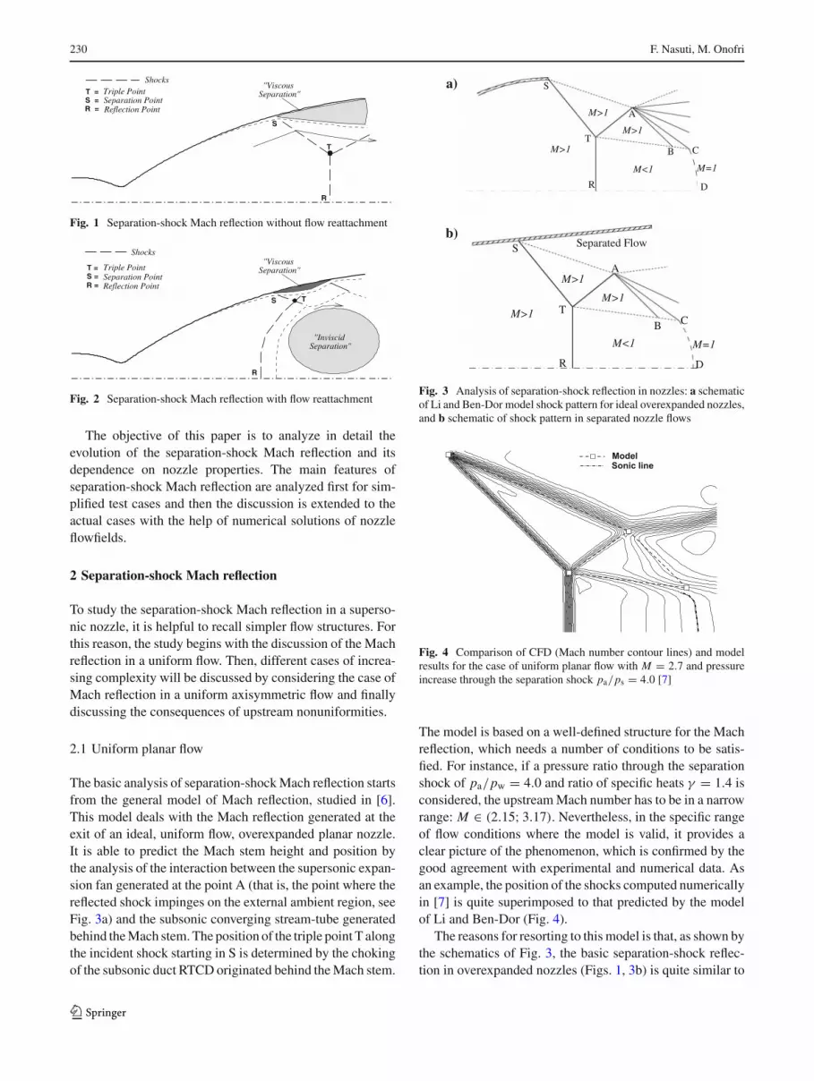
Fig. 1 Separation-shock Mach reflection without flow reattachment
"InviscidSeparation"
"ViscousSeparation"
Shocks
T = Triple Point
R = Reflection PointSeparation PointS =
S T
R
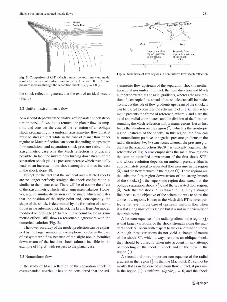
Fig. 2 Separation-shock Mach reflection with flow reattachment
The objective of this paper is to analyze in detail theevolution of the separation-shock Mach reflection and itsdependence on nozzle properties. The main features ofseparation-shock Mach reflection are analyzed first for sim-plified test cases and then the discussion is extended to theactual cases with the help of numerical solutions of nozzleflowfields.
2 Separation-shock Mach reflection
To study the separation-shock Mach reflection in a superso-nic nozzle, it is helpful to recall simpler flow structures. Forthis reason, the study begins with the discussion of the Machreflection in a uniform flow. Then, different cases of increa-sing complexity will be discussed by considering the case ofMach reflection in a uniform axisymmetric flow and finallydiscussing the consequences of upstream nonuniformities.
2.1 Uniform planar flow
The basic analysis of separation-shock Mach reflection startsfrom the general model of Mach reflection, studied in [6].This model deals with the Mach reflection generated at theexit of an ideal, uniform flow, overexpanded planar nozzle.It is able to predict the Mach stem height and position bythe analysis of the interaction between the supersonic expan-sion fan generated at the point A (that is, the point where thereflected shock impinges on the external ambient region, seeFig. 3a) and the subsonic converging stream-tube generatedbehind the Mach stem. The position of the triple point T alongthe incident shock starting in S is determined by the chokingof the subsonic duct RTCD originated behind the Mach stem.
a)
R D
CB
AM>1
M=1M<1
M>1
M>1T
S
b)Separated FlowS
T
R
A
B C
D
M>1
M<1 M=1
M>1
M>1
Fig. 3 Analysis of separation-shock reflection in nozzles: a schematicof Li and Ben-Dor model shock pattern for ideal overexpanded nozzles,and b schematic of shock pattern in separated nozzle flows
ModelSonic line
Fig. 4 Comparison of CFD (Mach number contour lines) and modelresults for the case of uniform planar flow with M = 2.7 and pressureincrease through the separation shock pa/ps = 4.0 [7]
The model is based on a well-defined structure for the Machreflection, which needs a number of conditions to be satis-fied. For instance, if a pressure ratio through the separationshock of pa/pw = 4.0 and ratio of specific heats γ = 1.4 isconsidered, the upstream Mach number has to be in a narrowrange: M ∈ (2.15; 3.17). Nevertheless, in the specific rangeof flow conditions where the model is valid, it provides aclear picture of the phenomenon, which is confirmed by thegood agreement with experimental and numerical data. Asan example, the position of the shocks computed numericallyin [7] is quite superimposed to that predicted by the modelof Li and Ben-Dor (Fig. 4).
The reasons for resorting to this model is that, as shown bythe schematics of Fig. 3, the basic separation-shock reflec-tion in overexpanded nozzles (Figs. 1, 3b) is quite similar to
123
Shock structure in separated nozzle flows 231
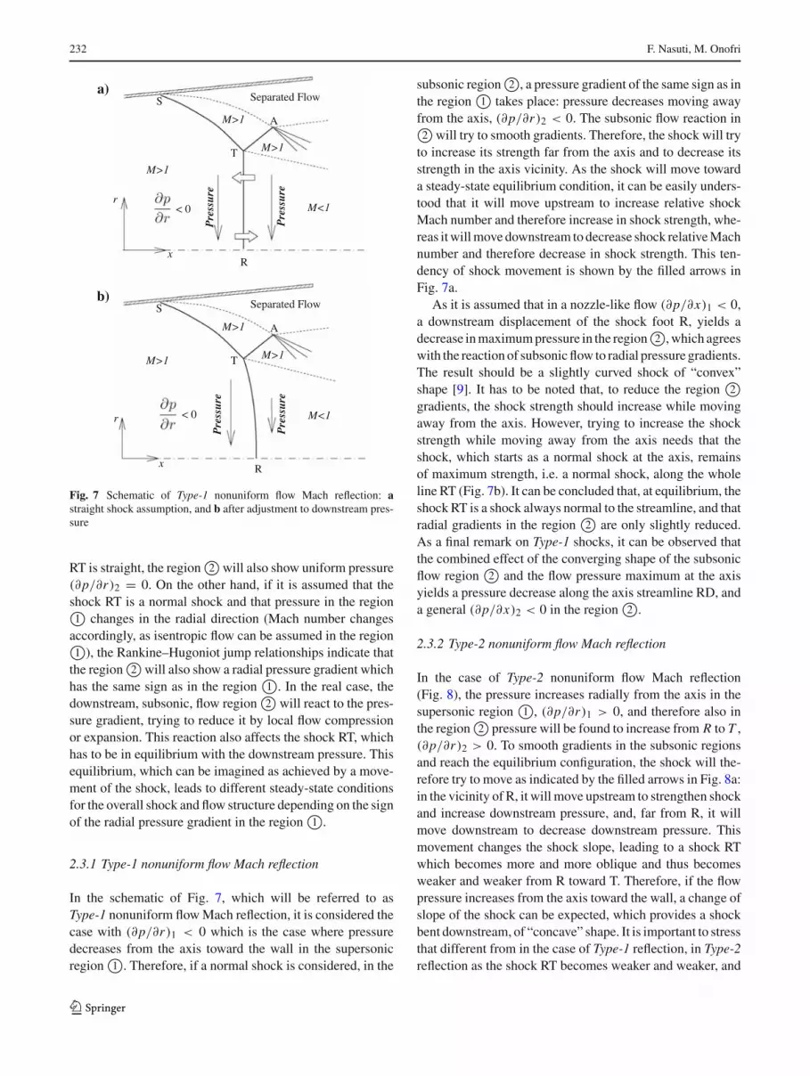
ModelSonic line
Fig. 5 Comparison of CFD (Mach number contour lines) and modelresults for the case of uniform axisymmetric flow with M = 2.7 andpressure increase through the separation shock pa/ps = 4.0 [7]
the shock reflection generated at the exit of an ideal nozzle(Fig. 3a).
2.2 Uniform axisymmetric flow
As a second step toward the analysis of separated shock struc-ture in nozzle flows, let us remove the planar flow assump-tion, and consider the case of the reflection of an obliqueshock propagating in a uniform, axisymmetric flow. First, itmust be stressed that while in the case of planar flow eitherregular or Mach reflection can occur depending on upstreamflow conditions and separation-shock pressure ratio, in theaxisymmetric case only the Mach reflection is physicallypossible. In fact, the inward flow turning downstream of theseparation-shock yields a pressure increase which eventuallyleads to an increase in the shock strength and thus increasein the shock slope [8].
Except for the fact that the incident and reflected shocksare no longer perfectly straight, the shock configuration issimilar to the planar case. There will be of course the effectof the axisymmetry, which will change mass balances. Howe-ver, a quite similar discussion can be made which indicatesthat the position of the triple point and, consequently, theshape of the shock, is determined by the formation of a sonicthroat in the subsonic duct. In fact, the Li and Ben-Dor model,modified according to [7] to take into account for the axisym-metric effects, still shows a reasonable agreement with thenumerical solution (Fig. 5).
The lower accuracy of the model prediction can be explai-ned by the larger number of assumptions needed in the caseof axisymmetric flow because of the slight nonuniformitiesdownstream of the incident shock (almost invisible in theexample of Fig. 5) with respect to the planar case.
2.3 Nonuniform flow
In the study of Mach reflection of the separation shock inoverexpanded nozzles it has to be considered that the axi-
of the shockregion upstreamSupersonic flow
of the shockregion downstreamSubsonic flow
1 2
3
4Nozzle Wall
r
S
R
T
M>1 M<1
x
M>1
Separated flow region
A
Fig. 6 Schematic of flow regions in nonuniform flow Mach reflection
line because the objective of the schematic was to show theabove flow regions. However, the Mach disk RT is never per-fectly flat, even in the case of upstream uniform flow whenit is flat along most of its length but it is not in the vicinity ofthe triple point.
to increase its strength far from the axis and to decrease itsstrength in the axis vicinity. As the shock will move towarda steady-state equilibrium condition, it can be easily unders-tood that it will move upstream to increase relative shockMach number and therefore increase in shock strength, whe-reas it will move downstream to decrease shock relative Machnumber and therefore decrease in shock strength. This ten-dency of shock movement is shown by the filled arrows inFig. 7a.
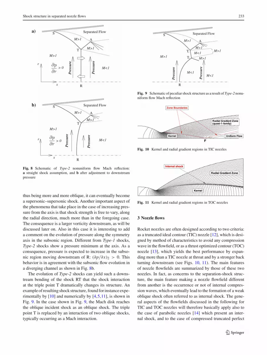
Fig. 8 Schematic of Type-2 nonuniform flow Mach reflection:a straight shock assumption, and b after adjustment to downstreampressure
thus being more and more oblique, it can eventually becomea supersonic–supersonic shock. Another important aspect ofthe phenomena that take place in the case of increasing pres-sure from the axis is that shock strength is free to vary, alongthe radial direction, much more than in the foregoing case.The consequence is a larger vorticity downstream, as will bediscussed later on. Also in this case it is interesting to adda comment on the evolution of pressure along the symmetryaxis in the subsonic region. Different from Type-1 shocks,Type-2 shocks show a pressure minimum at the axis. As aconsequence, pressure is expected to increase in the subso-nic region moving downstream of R: (∂p/∂x)2 > 0. Thisbehavior is in agreement with the subsonic flow evolution ina diverging channel as shown in Fig. 8b.
The evolution of Type-2 shocks can yield such a downs-tream bending of the shock RT that the shock interactionat the triple point T dramatically changes its structure. Anexample of resulting shock structure, found for instance expe-rimentally by [10] and numerically by [4,5,11], is shown inFig. 9. In the case shown in Fig. 9, the Mach disk reachesthe oblique incident shock as an oblique shock. The triplepoint T is replaced by an interaction of two oblique shocks,typically occurring as a Mach interaction.
A
S
M>1
T
M>1
Separated Flow
Pre
ssur
e
Pre
ssur
e
M<1
M>1
M<1M>1
M<1
M>1
R
T
1
2
Fig. 9 Schematic of peculiar shock structure as a result of Type-2 nonu-niform flow Mach reflection
Kernel
Zone Boundaries
Radial Gradient Zone(quasi-1-family)
Uniform Flow
F
Fig. 10 Kernel and radial gradient regions in TIC nozzles
Kernel
Internal shock
Radial Gradient Zone
Fig. 11 Kernel and radial gradient regions in TOC nozzles
3 Nozzle flows
Rocket nozzles are often designed according to two criteria:as a truncated ideal contour (TIC) nozzle [12], which is desi-gned by method of characteristics to avoid any compressionwave in the flowfield, or as a thrust optimized contour (TOC)nozzle [13], which yields the best performance by expan-ding more than a TIC nozzle at throat and by a stronger backturning downstream (see Figs. 10, 11). The main featuresof nozzle flowfields are summarized by those of these twonozzles. In fact, as concerns to the separation-shock struc-ture, the main feature making a nozzle flowfield differentfrom another is the occurrence or not of internal compres-sion waves, which eventually lead to the formation of a weakoblique shock often referred to as internal shock. The gene-ral aspects of the flowfields discussed in the following forTIC and TOC nozzles will therefore basically apply also tothe case of parabolic nozzles [14] which present an inter-nal shock, and to the case of compressed truncated perfect
123
234 F. Nasuti, M. Onofri
nozzles [15] where the appearance or not of the internal shockdepends on the compression factor value [16].
The Mach number contour lines displayed in Figs. 10, 11are helpful to understand gradients in TIC and TOP nozzles.In both cases, the first region can be identified as the kernelregion, where the flowfield depends only on the expansionat throat. It is a two-family region, yielded by the expansionwaves generated by the flow of the supersonic jet around theconvex wall in the throat region and by its reflection atthe nozzle axis. The kernel region is therefore bounded bythe wave propagating from the point of the inflection of thewall downstream of the throat, or by steeper waves propa-gating from further downstream wall points. The latter canonly be compression waves coalescing in a weak shock: itis the aforementioned internal shock. In the kernel region,the flow is nearly uniform in the radial direction. There isonly a slight negative radial gradient, meaning that pres-sure slightly decreases from the axis. If the Mach disk ofthe separation-shock reflection would lie in the kernel, theflow conditions would be those of Type-1 nonuniform flowMach reflection (Fig. 7). Therefore, a slight backward ben-ding that will approximately follow Mach number contourlines can be expected.
Between the kernel and the back-turning wall, there is aregion with large radial gradients in both TIC and TOC nozzlecases. The difference is that in the case of TOC nozzle thereis a first local nonuniformity carried by the internal shock,whereas in the case of TIC nozzle the radial gradients arespread over the whole region. The radial pressure gradientis positive, both at the internal shock and in the upper part,meaning that pressure increases moving away from the axis.Therefore, if the Mach disk of the separation-shock reflection(or part of it) lies in the “radial gradient” region, the flowconditions would be those leading to Type-2 nonuniform flowMach reflection (Fig. 8).
Finally, a uniform (TIC nozzle) or nearly uniform regiontakes place downstream of the kernel. If the Mach disk of theseparation-shock reflection (or part of it) lies in the “uniformflow” region, the flow conditions would be those leading tothe uniform axisymmetric flow Mach reflection discussed inSect. 2.2.
To understand better the effect of upstream gradients onthe shape of the Mach disk, the following test has been car-ried out. A TIC nozzle shape has been considered, which isthe one presenting the smoothest gradient, and on its Eulerflowfield a possible shock is drawn starting at different posi-tions along the nozzle axis. The shock is drawn followingthe comments discussed above. In particular, the part of theshock lying inside the kernel is drawn as a normal shock(as in Type-1 shocks), and the part of the shock lying in theradial gradient region is drawn as an oblique shock providingthe same pressure downstream as that obtained at the kernelboundary (“constant pressure value”, it is the limiting case
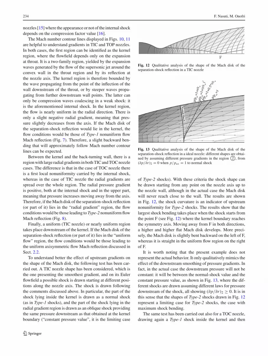
Fig. 12 Qualitative analysis of the shape of the Mach disk of theseparation-shock reflection in a TIC nozzle
of Type-2 shocks). With these criteria the shock shape canbe drawn starting from any point on the nozzle axis up tothe nozzle wall, although in the actual case the Mach diskwill never reach close to the wall. The results are shownin Fig. 12, the shock curvature is an indicator of upstreamnonuniformity for Type-2 shocks. The results show that thelargest shock bending takes place when the shock starts fromthe point F (see Fig. 12) where the kernel boundary reachesthe symmetry axis. Moving away from F in both directions,a higher and higher flat Mach disk develops. More preci-sely, the Mach disk is slightly bent backward on the left of F,whereas it is straight in the uniform flow region on the rightof F.
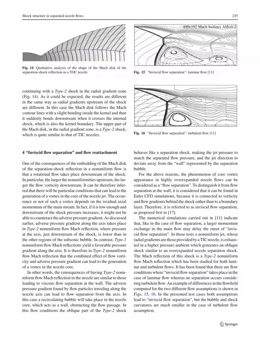
It is worth noting that the present example does notrepresent the actual behavior. It only qualitatively mimics theeffect of the downstream smoothing of pressure gradients. Infact, in the actual case the downstream pressure will not beconstant: it will be between the normal-shock value and theconstant pressure value, as shown in Fig. 13, where the dif-ferent shocks are drawn assuming different laws for pressuredownstream of the shock, all showing (∂p/∂r)2 ≥ 0. It is inthis sense that the shapes of Type-2 shocks drawn in Fig. 12represent a limiting case for Type-2 shocks, the case withmaximum shock bending.
The same test has been carried out also for a TOC nozzle,drawing again a Type-1 shock inside the kernel and then
123
Shock structure in separated nozzle flows 235
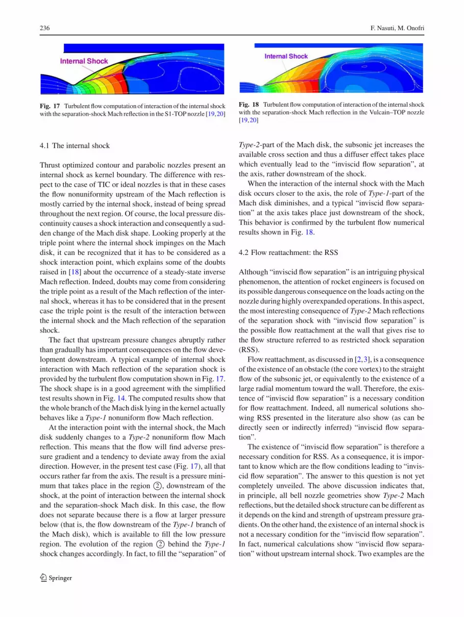
Fig. 14 Qualitative analysis of the shape of the Mach disk of theseparation-shock reflection in a TOC nozzle
continuing with a Type-2 shock in the radial gradient zone(Fig. 14). As it could be expected, the results are differentin the same way as radial gradients upstream of the shockare different. In this case the Mach disk follows the Machcontour lines with a slight bending inside the kernel and thenit suddenly bends downstream when it crosses the internalshock, which is also the kernel boundary. The upper part ofthe Mach disk, in the radial gradient zone, is a Type-2 shock,which is quite similar to that of TIC nozzles.
4 “Inviscid flow separation” and flow reattachment
One of the consequences of the embedding of the Mach diskof the separation-shock reflection in a nonuniform flow isthat a rotational flow takes place downstream of the shock.In particular, the larger the nonuniformities upstream, the lar-ger the flow vorticity downstream. It can be therefore infer-red that there will be particular conditions that can lead to thegeneration of a vortex in the core of the nozzle jet. The occur-rence or not of such a vortex depends on the residual axialmomentum of the main stream. In fact, if it is low enough anddownstream of the shock pressure increases, it might not beable to counteract the adverse pressure gradient. As discussedearlier, adverse pressure gradient along the axis takes placein Type-2 nonuniform flow Mach reflection, where pressureat the axis, just downstream of the shock, is lower than inthe other regions of the subsonic bubble. In contrast, Type-1nonuniform flow Mach reflections yield a favorable pressuregradient along the axis. It is therefore in Type-2 nonuniformflow Mach reflection that the combined effect of flow vorti-city and adverse pressure gradient can lead to the generationof a vortex in the nozzle core.
In other words, the consequences of having Type-2 nonu-niform flow Mach reflection in the nozzle are similar to thoseleading to viscous flow separation at the wall. The adversepressure gradient found by flow particles traveling along thenozzle axis can lead to flow separation from the axis. Inthis case a recirculating bubble will take place in the nozzlecore, which acts as a wall, obstructing the flow passage. Inthis flow conditions the oblique part of the Type-2 shock
behaves like a separation shock, making the jet pressure tomatch the separated flow pressure, and the jet direction todeviate away from the “wall” represented by the separationbubble.
For the above reasons, the phenomenon of core vortexappearance in highly overexpanded nozzle flows can beconsidered as a “flow separation”. To distinguish it from flowseparation at the wall, it is considered that it can be found inEuler CFD simulations, because it is connected to vorticityand flow gradients behind the shock rather than to a boundarylayer. Therefore, it is referred to as inviscid flow separation,as proposed first in [17].
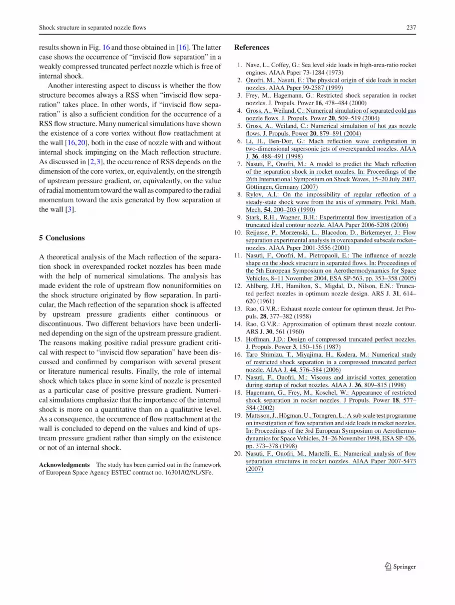
The numerical simulations carried out in [11] indicatethat, like in the case of flow separation, a larger momentumexchange in the main flow may delay the onset of “invis-cid flow separation”. In these tests a nonuniform jet, whoseradial gradients are those provided by a TIC nozzle, is exhaus-ted in a higher pressure ambient which generates an obliqueshock similar to an overexpanded nozzle separation shock.The Mach reflection of this shock is a Type-2 nonuniformflow Mach reflection which has been studied for both lami-nar and turbulent flows. It has been found that there are flowconditions where “inviscid flow separation” takes place in thecase of laminar flow whereas no separation occurs conside-ring turbulent flow. An example of differences in the flowfieldcomputed for the two different flow assumptions is shown inFigs. 15, 16. In the presented test cases both assumptionslead to “inviscid flow separation”, but the bubble and shockcurvatures are much smaller in the case of turbulent flowassumption.
123
236 F. Nasuti, M. Onofri
Fig. 17 Turbulent flow computation of interaction of the internal shockwith the separation-shock Mach reflection in the S1-TOP nozzle [19,20]
4.1 The internal shock
Thrust optimized contour and parabolic nozzles present aninternal shock as kernel boundary. The difference with res-pect to the case of TIC or ideal nozzles is that in these casesthe flow nonuniformity upstream of the Mach reflection ismostly carried by the internal shock, instead of being spreadthroughout the next region. Of course, the local pressure dis-continuity causes a shock interaction and consequently a sud-den change of the Mach disk shape. Looking properly at thetriple point where the internal shock impinges on the Machdisk, it can be recognized that it has to be considered as ashock interaction point, which explains some of the doubtsraised in [18] about the occurrence of a steady-state inverseMach reflection. Indeed, doubts may come from consideringthe triple point as a result of the Mach reflection of the inter-nal shock, whereas it has to be considered that in the presentcase the triple point is the result of the interaction betweenthe internal shock and the Mach reflection of the separationshock.
The fact that upstream pressure changes abruptly ratherthan gradually has important consequences on the flow deve-lopment downstream. A typical example of internal shockinteraction with Mach reflection of the separation shock isprovided by the turbulent flow computation shown in Fig. 17.The shock shape is in a good agreement with the simplifiedtest results shown in Fig. 14. The computed results show thatthe whole branch of the Mach disk lying in the kernel actuallybehaves like a Type-1 nonuniform flow Mach reflection.
Fig. 18 Turbulent flow computation of interaction of the internal shockwith the separation-shock Mach reflection in the Vulcain–TOP nozzle[19,20]
Type-2-part of the Mach disk, the subsonic jet increases theavailable cross section and thus a diffuser effect takes placewhich eventually lead to the “inviscid flow separation”, atthe axis, rather downstream of the shock.
When the interaction of the internal shock with the Machdisk occurs closer to the axis, the role of Type-1-part of theMach disk diminishes, and a typical “inviscid flow separa-tion” at the axis takes place just downstream of the shock,This behavior is confirmed by the turbulent flow numericalresults shown in Fig. 18.
4.2 Flow reattachment: the RSS
Although “inviscid flow separation” is an intriguing physicalphenomenon, the attention of rocket engineers is focused onits possible dangerous consequence on the loads acting on thenozzle during highly overexpanded operations. In this aspect,the most interesting consequence of Type-2 Mach reflectionsof the separation shock with “inviscid flow separation” isthe possible flow reattachment at the wall that gives rise tothe flow structure referred to as restricted shock separation(RSS).
Flow reattachment, as discussed in [2,3], is a consequenceof the existence of an obstacle (the core vortex) to the straightflow of the subsonic jet, or equivalently to the existence of alarge radial momentum toward the wall. Therefore, the exis-tence of “inviscid flow separation” is a necessary conditionfor flow reattachment. Indeed, all numerical solutions sho-wing RSS presented in the literature also show (as can bedirectly seen or indirectly inferred) “inviscid flow separa-tion”.
The existence of “inviscid flow separation” is therefore anecessary condition for RSS. As a consequence, it is impor-tant to know which are the flow conditions leading to “invis-cid flow separation”. The answer to this question is not yetcompletely unveiled. The above discussion indicates that,in principle, all bell nozzle geometries show Type-2 Machreflections, but the detailed shock structure can be different asit depends on the kind and strength of upstream pressure gra-dients. On the other hand, the existence of an internal shock isnot a necessary condition for the “inviscid flow separation”.In fact, numerical calculations show “inviscid flow separa-tion” without upstream internal shock. Two examples are the
123
Shock structure in separated nozzle flows 237
results shown in Fig. 16 and those obtained in [16]. The lattercase shows the occurrence of “inviscid flow separation” in aweakly compressed truncated perfect nozzle which is free ofinternal shock.
Another interesting aspect to discuss is whether the flowstructure becomes always a RSS when “inviscid flow sepa-ration” takes place. In other words, if “inviscid flow sepa-ration” is also a sufficient condition for the occurrence of aRSS flow structure. Many numerical simulations have shownthe existence of a core vortex without flow reattachment atthe wall [16,20], both in the case of nozzle with and withoutinternal shock impinging on the Mach reflection structure.As discussed in [2,3], the occurrence of RSS depends on thedimension of the core vortex, or, equivalently, on the strengthof upstream pressure gradient, or, equivalently, on the valueof radial momentum toward the wall as compared to the radialmomentum toward the axis generated by flow separation atthe wall [3].
5 Conclusions
A theoretical analysis of the Mach reflection of the separa-tion shock in overexpanded rocket nozzles has been madewith the help of numerical simulations. The analysis hasmade evident the role of upstream flow nonuniformities onthe shock structure originated by flow separation. In parti-cular, the Mach reflection of the separation shock is affectedby upstream pressure gradients either continuous ordiscontinuous. Two different behaviors have been underli-ned depending on the sign of the upstream pressure gradient.The reasons making positive radial pressure gradient criti-cal with respect to “inviscid flow separation” have been dis-cussed and confirmed by comparison with several presentor literature numerical results. Finally, the role of internalshock which takes place in some kind of nozzle is presentedas a particular case of positive pressure gradient. Numeri-cal simulations emphasize that the importance of the internalshock is more on a quantitative than on a qualitative level.As a consequence, the occurrence of flow reattachment at thewall is concluded to depend on the values and kind of ups-tream pressure gradient rather than simply on the existenceor not of an internal shock.
Acknowledgments The study has been carried out in the frameworkof European Space Agency ESTEC contract no. 16301/02/NL/SFe.
References
1. Nave, L., Coffey, G.: Sea level side loads in high-area-ratio rocketengines. AIAA Paper 73-1284 (1973)
2. Onofri, M., Nasuti, F.: The physical origin of side loads in rocketnozzles. AIAA Paper 99-2587 (1999)
3. Frey, M., Hagemann, G.: Restricted shock separation in rocketnozzles. J. Propuls. Power 16, 478–484 (2000)
4. Gross, A., Weiland, C.: Numerical simulation of separated cold gasnozzle flows. J. Propuls. Power 20, 509–519 (2004)
5. Gross, A., Weiland, C.: Numerical simulation of hot gas nozzleflows. J. Propuls. Power 20, 879–891 (2004)
7. Nasuti, F., Onofri, M.: A model to predict the Mach reflectionof the separation shock in rocket nozzles. In: Proceedings of the26th International Symposium on Shock Waves, 15–20 July 2007.Göttingen, Germany (2007)
8. Rylov, A.I.: On the impossibility of regular reflection of asteady-state shock wave from the axis of symmetry. Prikl. Math.Mech. 54, 200–203 (1990)
9. Stark, R.H., Wagner, B.H.: Experimental flow investigation of atruncated ideal contour nozzle. AIAA Paper 2006-5208 (2006)
10. Reijasse, P., Morzenski, L., Blacodon, D., Birkemeyer, J.: Flowseparation experimental analysis in overexpanded subscale rocket–nozzles. AIAA Paper 2001-3556 (2001)
11. Nasuti, F., Onofri, M., Pietropaoli, E.: The influence of nozzleshape on the shock structure in separated flows. In: Proceedings ofthe 5th European Symposium on Aerothermodynamics for SpaceVehicles, 8–11 November 2004, ESA SP-563, pp. 353–358 (2005)
12. Ahlberg, J.H., Hamilton, S., Migdal, D., Nilson, E.N.: Trunca-ted perfect nozzles in optimum nozzle design. ARS J. 31, 614–620 (1961)
14. Rao, G.V.R.: Approximation of optimum thrust nozzle contour.ARS J. 30, 561 (1960)
15. Hoffman, J.D.: Design of compressed truncated perfect nozzles.J. Propuls. Power 3, 150–156 (1987)
16. Taro Shimizu, T., Miyajima, H., Kodera, M.: Numerical studyof restricted shock separation in a compressed truncated perfectnozzle. AIAA J. 44, 576–584 (2006)
17. Nasuti, F., Onofri, M.: Viscous and inviscid vortex generationduring startup of rocket nozzles. AIAA J. 36, 809–815 (1998)
18. Hagemann, G., Frey, M., Koschel, W.: Appearance of restrictedshock separation in rocket nozzles. J Propuls. Power 18, 577–584 (2002)
19. Mattsson, J., Högman, U., Torngren, L.: A sub scale test programmeon investigation of flow separation and side loads in rocket nozzles.In: Proceedings of the 3rd European Symposium on Aerothermo-dynamics for Space Vehicles, 24–26 November 1998, ESA SP-426,pp. 373–378 (1998)
20. Nasuti, F., Onofri, M., Martelli, E.: Numerical analysis of flowseparation structures in rocket nozzles. AIAA Paper 2007-5473(2007)