Fast identification of O 2 corrosion in economiser tubes HockChye Qua, ChwinChieh Khaw ⇑ , ChingSeong Tan, Xin Wang, JongBoon Ooi Faculty of Engineering and Science, Universiti Tunku Abdul Rahman, Jalan Genting Kelang, 53300 Setapak, Kuala Lumpur, Malaysia article info Article history: Received 9 June 2011 Accepted 20 July 2011 Available online 27 July 2011 Keywords: Boiler failure Economiser tube Metallography Pitting corrosion abstract Failure investigation was conducted on three tube samples via visual/metallographic exam- ination and analysis of operational history. The investigation employed a fast-identification approach, which allowed a shorter down time and faster production recovery after tube fail- ure. Visual and metallographic evidence showed that the tube samples had suffered from abnormally high wastage at the external and internal surfaces; the latter surface, in addition had suffered from deep pitting. Analysis of operational history confirmed the presence of dissolved O 2 in the feedwater. It was concluded that leakage was primarily caused by tube thinning from internal wastage/pitting, aggravated by external wastage. Ó 2011 Elsevier Ltd. All rights reserved. 1. Introduction Boilers are used to heat water to generate steam for a variety of purposes. Boiler components such as economisers, water- wall tubes and superheaters are today mainly made of steels and high temperature alloys. An economiser is a heat exchanger located in the lower gas temperature region (450–600 °C), designed to recover some of the heat from the discharged flue gas. It consists of a series of tubes through which feed water flows to the drum or to the inlet headers of furnace walls. Flue gases flow over the outside of the tubes. Economisers can be constructed with cast iron or steel tubes; the former is usually used in low-pressure industrial boilers (pressure 6 2.5 MPa) and the latter, in high pressure boilers [1]. Failure of boiler tubes is a very common phenomenon, therefore it is important to investigate their root causes to prevent future occurrences [2,3]. López-López et al. [4] investigated the association between the carburisation of austenitic stainless steels and high fireside corrosion rates. The methodology encompassed microhardness profiling, electron probe microanal- ysis and metallographic studies of the external surfaces of superheater and reheater tubes. Chaudhuri [5] described case studies related to failures of a 1.25Cr–0.5Mo reheater tube, a carbon steel tube and some 2.25Cr–1Mo final superheater tubes. Lee et al. [6] presented failure analysis cases on final superheater tubes in an ultra-supercritical coal power plant. Ah- mad et al. [7] investigated the failure of a SA210-A1, rear water-wall tube by visual site inspection, tube wall thickness mea- surements and metallographic examination. Saha et al. [8] examined the probable causes of failure of a welded joint in a 210 MW thermal power plant. Dhua [9] investigated failed water-wall tubes from a thermal power station via visual exam- ination, metallographic examination, and electron probe microanalysis. The reasons for boiler tube failures are varied, and common mechanisms include pitting, erosion, thermal fatigue, creep and stress corrosion cracking [2,3,10,11]; other more complex ones include stress assisted corrosion, caustic gouging and acid phosphate corrosion. Some of the failures, for example pitting, are caused by dissolved oxygen in the feed water. In boil- ers, water coming out of deaerators usually has some residual oxygen, which is removed chemically. Sodium sulphite and hydrazine, or some other chemicals, are used for removal of residual oxygen; sodium sulphite is used for low pressure boilers. 1350-6307/$ - see front matter Ó 2011 Elsevier Ltd. All rights reserved. doi:10.1016/j.engfailanal.2011.07.014 ⇑ Corresponding author. Tel.: +60 341079802; fax: +60 341079803. E-mail address: [email protected](C.C. Khaw). Engineering Failure Analysis 18 (2011) 2201–2210 Contents lists available at SciVerse ScienceDirect Engineering Failure Analysis journal homepage: www.elsevier.com/locate/engfailanal
Transcript
Engineering Failure Analysis 18 (2011) 2201–2210
Contents lists available at SciVerse ScienceDirect
Fast identification of O2 corrosion in economiser tubes
HockChye Qua, ChwinChieh Khaw ⇑, ChingSeong Tan, Xin Wang, JongBoon OoiFaculty of Engineering and Science, Universiti Tunku Abdul Rahman, Jalan Genting Kelang, 53300 Setapak, Kuala Lumpur, Malaysia
a r t i c l e i n f o
Article history:Received 9 June 2011Accepted 20 July 2011Available online 27 July 2011
Failure investigation was conducted on three tube samples via visual/metallographic exam-ination and analysis of operational history. The investigation employed a fast-identificationapproach, which allowed a shorter down time and faster production recovery after tube fail-ure. Visual and metallographic evidence showed that the tube samples had suffered fromabnormally high wastage at the external and internal surfaces; the latter surface, in additionhad suffered from deep pitting. Analysis of operational history confirmed the presence ofdissolved O2 in the feedwater. It was concluded that leakage was primarily caused by tubethinning from internal wastage/pitting, aggravated by external wastage.
� 2011 Elsevier Ltd. All rights reserved.
1. Introduction
Boilers are used to heat water to generate steam for a variety of purposes. Boiler components such as economisers, water-wall tubes and superheaters are today mainly made of steels and high temperature alloys. An economiser is a heat exchangerlocated in the lower gas temperature region (450–600 �C), designed to recover some of the heat from the discharged flue gas.It consists of a series of tubes through which feed water flows to the drum or to the inlet headers of furnace walls. Flue gasesflow over the outside of the tubes. Economisers can be constructed with cast iron or steel tubes; the former is usually used inlow-pressure industrial boilers (pressure 6 2.5 MPa) and the latter, in high pressure boilers [1].
Failure of boiler tubes is a very common phenomenon, therefore it is important to investigate their root causes to preventfuture occurrences [2,3]. López-López et al. [4] investigated the association between the carburisation of austenitic stainlesssteels and high fireside corrosion rates. The methodology encompassed microhardness profiling, electron probe microanal-ysis and metallographic studies of the external surfaces of superheater and reheater tubes. Chaudhuri [5] described casestudies related to failures of a 1.25Cr–0.5Mo reheater tube, a carbon steel tube and some 2.25Cr–1Mo final superheatertubes. Lee et al. [6] presented failure analysis cases on final superheater tubes in an ultra-supercritical coal power plant. Ah-mad et al. [7] investigated the failure of a SA210-A1, rear water-wall tube by visual site inspection, tube wall thickness mea-surements and metallographic examination. Saha et al. [8] examined the probable causes of failure of a welded joint in a210 MW thermal power plant. Dhua [9] investigated failed water-wall tubes from a thermal power station via visual exam-ination, metallographic examination, and electron probe microanalysis.
The reasons for boiler tube failures are varied, and common mechanisms include pitting, erosion, thermal fatigue, creepand stress corrosion cracking [2,3,10,11]; other more complex ones include stress assisted corrosion, caustic gouging andacid phosphate corrosion. Some of the failures, for example pitting, are caused by dissolved oxygen in the feed water. In boil-ers, water coming out of deaerators usually has some residual oxygen, which is removed chemically. Sodium sulphite andhydrazine, or some other chemicals, are used for removal of residual oxygen; sodium sulphite is used for low pressureboilers.
2202 H.C. Qua et al. / Engineering Failure Analysis 18 (2011) 2201–2210
Boiler tube failure investigations often involve the use of advanced diagnostic equipment such as SEM/EDX and XRD,which are costly and time consuming to perform [4,12]. However, with a good understanding of the operational featuresof the plant, and of boiler tube failure mechanisms, a fast and accurate analysis may be made with only minimal usage ofexpensive laboratory equipment.
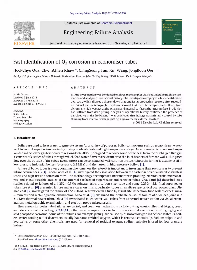
This paper presented a case where a fast, low cost investigation was successfully conducted on O2 corrosion of economis-er tubes, many of which were reported to have leaked. Speed was of the main essence, as decisions had to be made regardingthe extent of repairs necessary, to allow the boiler to come on-stream again in the shortest possible time. In the presentwork, three tube samples from leaking economiser tubes were submitted for investigation; they were designated as TubeA, Tube B and Tube C (Fig. 1). The tubes came from a biomass boiler producing steam for processing palm oil fruit andfor power generation.
2. Materials and methods
The original outer diameter (OD) was given to be 38.1 mm, and the thickness, 4.0 mm. The outer diameters of the sup-plied tubes were first measured at the Locations 1–5 of Fig. 1. Longitudinal and transverse specimens were then cut out fromthese locations, mounted and prepared for metallographic examination. Wall thicknesses were measured from the mountedspecimens. The boiler operating log for a period of about one year preceding the first detected tube leakage was summarisedand tabulated for easy comparison. The main parameters looked at were sulphite content, total Fe content, and appearance ofthe water. Where O2 content was analysed, the results were noted. Finally, SEM/EDX analysis was performed on the internaland external deposits of Tube A to confirm the accuracy of the fast investigation.
3. Results and discussion
3.1. Laboratory examination
3.1.1. Visual examinationNone of the supplied tubes contained any leaking areas or visible bulging; their external surfaces were rough, lightly pit-
ted all over and contained light brownish oxides (Figs. 1 and 2). Their internal surfaces were even rougher and containeddeeper pits with thicker brownish oxides (Figs. 3–7), except at areas where remnants of darkish oxides were present.
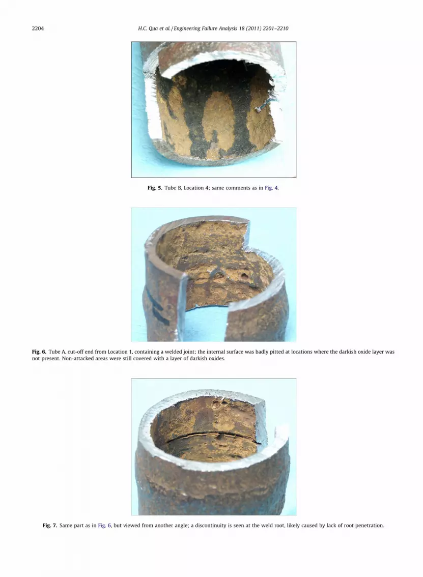
Figs. 6 and 7 show one end of Tube A containing a butt-welded joint; the internal surface at the vicinity of the joint haddeeper and more isolated pits than at other locations. A deep discontinuity was present over a part of the weld root, likelycaused by lack of root penetration.
3.1.2. Tube wall measurementsThe average OD and maximum/minimum wall thicknesses are shown in Table 1; the wall thicknesses were measured
from the sections shown in Fig. 8. These values must not be taken to be absolute; they are only values measured at the par-ticular micro-sections and it is very likely that other locations may have more extreme values. However, results generallyshow that there had been wastage on the outer surfaces; for an original OD of 38.1 mm, the maximum external thicknessloss detected would be 0.85 mm, at Location 1. The rest of the metal loss would have been due to wastage and pitting atthe internal surface; this amounted to 1.15 mm at pitted areas, leaving a remaining thickness of 2.0 mm, which was only50% of the original thickness.
1 2
3 4
5
Tube B Tube C Tube A
Fig. 1. The three tube samples supplied for examination, designated as Tube A, Tube B and Tube C; arrows 1–5 point to Locations from which Specimens 1–5 were cut out for metallographic examination.
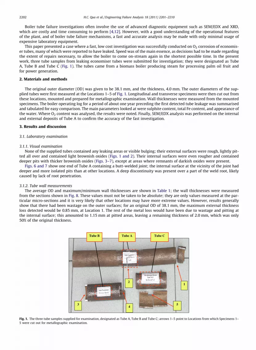
Fig. 2. Tube C, external surface, uniformly pitted all over; pits were however much lighter than at the internal surface.
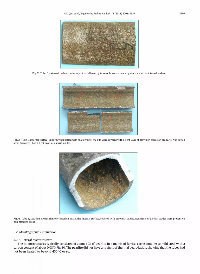
Fig. 3. Tube C, internal surface, uniformly populated with shallow pits; the pits were covered with a light layer of brownish corrosion products. Non-pittedareas (arrowed) had a light layer of darkish oxides.
Fig. 4. Tube B, Location 3, with shallow corrosion pits at the internal surface, covered with brownish oxides. Remnants of darkish oxides were present onnon-attacked areas.
H.C. Qua et al. / Engineering Failure Analysis 18 (2011) 2201–2210 2203
3.2. Metallographic examination
3.2.1. General microstructureThe microstructures typically consisted of about 10% of pearlite in a matrix of ferrite, corresponding to mild steel with a
carbon content of about 0.08% (Fig. 9). The pearlite did not have any signs of thermal degradation, showing that the tubes hadnot been heated to beyond 450 �C or so.
Fig. 5. Tube B, Location 4; same comments as in Fig. 4.
Fig. 6. Tube A, cut-off end from Location 1, containing a welded joint; the internal surface was badly pitted at locations where the darkish oxide layer wasnot present. Non-attacked areas were still covered with a layer of darkish oxides.
Fig. 7. Same part as in Fig. 6, but viewed from another angle; a discontinuity is seen at the weld root, likely caused by lack of root penetration.
2204 H.C. Qua et al. / Engineering Failure Analysis 18 (2011) 2201–2210
Table 1Outer diameter and thickness of tube samples supplied.
Tube Location (see Fig. 1) Average OD (mm) Thickness range (mm)
Tube A 1 36.4 2.1–3.42 36.6 2.0–2.9
Tube B 3 36.9 2.5–3.54 37.0 2.0–3.3
Tube C 5 Not measured 2.0–3.4
S2 S3
S4
S5 S1
Weld joint
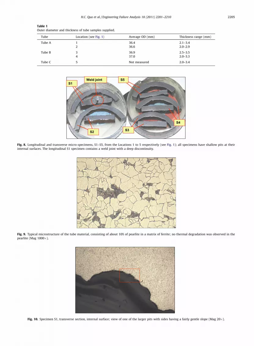
Fig. 8. Longitudinal and transverse micro-specimens, S1–S5, from the Locations 1 to 5 respectively (see Fig. 1); all specimens have shallow pits at theirinternal surfaces. The longitudinal S1 specimen contains a weld joint with a deep discontinuity.
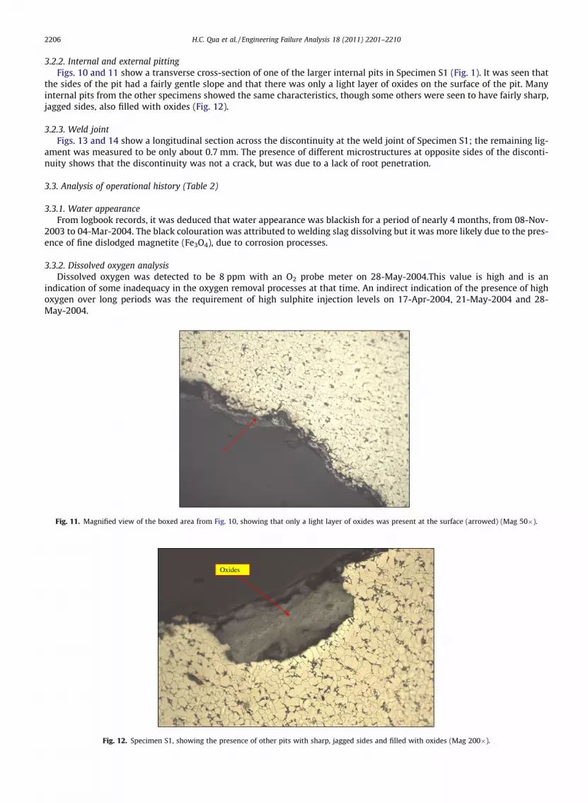
Fig. 9. Typical microstructure of the tube material, consisting of about 10% of pearlite in a matrix of ferrite; no thermal degradation was observed in thepearlite (Mag 1000�).
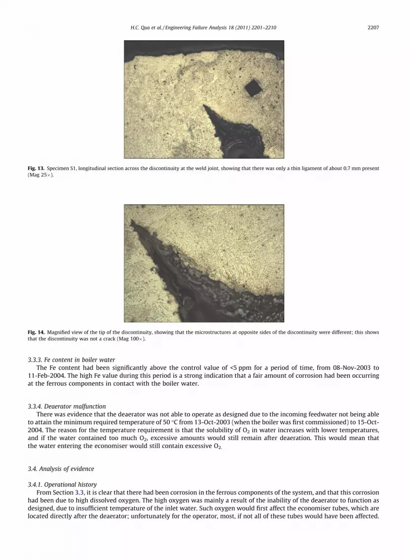
Fig. 10. Specimen S1, transverse section, internal surface; view of one of the larger pits with sides having a fairly gentle slope (Mag 20�).
H.C. Qua et al. / Engineering Failure Analysis 18 (2011) 2201–2210 2205
2206 H.C. Qua et al. / Engineering Failure Analysis 18 (2011) 2201–2210
3.2.2. Internal and external pittingFigs. 10 and 11 show a transverse cross-section of one of the larger internal pits in Specimen S1 (Fig. 1). It was seen that
the sides of the pit had a fairly gentle slope and that there was only a light layer of oxides on the surface of the pit. Manyinternal pits from the other specimens showed the same characteristics, though some others were seen to have fairly sharp,jagged sides, also filled with oxides (Fig. 12).
3.2.3. Weld jointFigs. 13 and 14 show a longitudinal section across the discontinuity at the weld joint of Specimen S1; the remaining lig-
ament was measured to be only about 0.7 mm. The presence of different microstructures at opposite sides of the disconti-nuity shows that the discontinuity was not a crack, but was due to a lack of root penetration.
3.3. Analysis of operational history (Table 2)
3.3.1. Water appearanceFrom logbook records, it was deduced that water appearance was blackish for a period of nearly 4 months, from 08-Nov-
2003 to 04-Mar-2004. The black colouration was attributed to welding slag dissolving but it was more likely due to the pres-ence of fine dislodged magnetite (Fe3O4), due to corrosion processes.
3.3.2. Dissolved oxygen analysisDissolved oxygen was detected to be 8 ppm with an O2 probe meter on 28-May-2004.This value is high and is an
indication of some inadequacy in the oxygen removal processes at that time. An indirect indication of the presence of highoxygen over long periods was the requirement of high sulphite injection levels on 17-Apr-2004, 21-May-2004 and 28-May-2004.
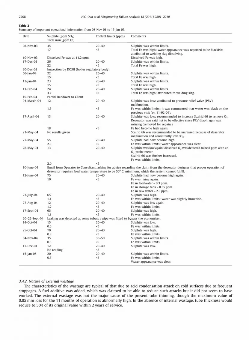
Fig. 11. Magnified view of the boxed area from Fig. 10, showing that only a light layer of oxides was present at the surface (arrowed) (Mag 50�).
Oxides
Fig. 12. Specimen S1, showing the presence of other pits with sharp, jagged sides and filled with oxides (Mag 200�).
Fig. 13. Specimen S1, longitudinal section across the discontinuity at the weld joint, showing that there was only a thin ligament of about 0.7 mm present(Mag 25�).
Fig. 14. Magnified view of the tip of the discontinuity, showing that the microstructures at opposite sides of the discontinuity were different; this showsthat the discontinuity was not a crack (Mag 100�).
H.C. Qua et al. / Engineering Failure Analysis 18 (2011) 2201–2210 2207
3.3.3. Fe content in boiler waterThe Fe content had been significantly above the control value of <5 ppm for a period of time, from 08-Nov-2003 to
11-Feb-2004. The high Fe value during this period is a strong indication that a fair amount of corrosion had been occurringat the ferrous components in contact with the boiler water.
3.3.4. Deaerator malfunctionThere was evidence that the deaerator was not able to operate as designed due to the incoming feedwater not being able
to attain the minimum required temperature of 50 �C from 13-Oct-2003 (when the boiler was first commissioned) to 15-Oct-2004. The reason for the temperature requirement is that the solubility of O2 in water increases with lower temperatures,and if the water contained too much O2, excessive amounts would still remain after deaeration. This would mean thatthe water entering the economiser would still contain excessive O2.
3.4. Analysis of evidence
3.4.1. Operational historyFrom Section 3.3, it is clear that there had been corrosion in the ferrous components of the system, and that this corrosion
had been due to high dissolved oxygen. The high oxygen was mainly a result of the inability of the deaerator to function asdesigned, due to insufficient temperature of the inlet water. Such oxygen would first affect the economiser tubes, which arelocated directly after the deaerator; unfortunately for the operator, most, if not all of these tubes would have been affected.
Table 2Summary of important operational information from 08-Nov-03 to 15-Jan-05.
Date Sulphite (ppm SO3) Control limits (ppm) CommentsTotal iron (ppm Fe)
08-Nov-03 35 20–40 Sulphite was within limits.17 <5 Total Fe was high; water appearance was reported to be blackish;
attributed to welding slag dissolving.10-Nov-03 Dissolved Fe was at 11.2 ppm. Dissolved Fe was high.17-Dec-03 26 20–40 Sulphite was within limits.
22 <5 Total Fe was high.30-Dec-03 Inspection by DOSH (boiler regulatory body)06-Jan-04 22 20–40 Sulphite was within limits.
15 <5 Total Fe was high.13-Jan-04 23 20–40 Sulphite was within limits.
15 <5 Total Fe was high.11-Feb-04 24 20–40 Sulphite was within limits.
33 <5 Total Fe was high; attributed to welding slag.19-Feb-04 Partial handover to Client04-March-04 12 20–40 Sulphite was low; attributed to pressure relief valve (PRV)
malfunction.1.5 <5 Fe was within limits; it was commented that water was black on the
previous visit (on 11-02-04).17-April-04 13 20–40 Sulphite was low; recommended to increase Scalrid 66 to remove O2.
Deaerator was said not to be effective since PRV diaphragm wasmissing (removed for repairs).
18 <5 Fe had become high again.21-May-04 No results given Scalrid 66 was recommended to be increased because of deaerator
malfunction and consistently low SO3.27-May-04 55 20–40 Sulphite had now become high.
2.3 <5 Fe was within limits; water appearance was clear.28-May-04 13 20–40 Sulphite was low again; dissolved O2 was detected to be 8 ppm with an
O2 probe meter.Scalrid 66 was further increased.Fe was within limits.
2.0 <510-June-04 Email from Operator to Consultant, asking for advice regarding the claim from the deaerator designer that proper operation of
deaerator requires feed water temperature to be 500 C, minimum, which the system cannot fulfill.12-June-04 75 20–40 Sulphite had now become high again.
10 <5 Fe was rising again.Fe in feedwater = 0.3 ppm.Fe in storage tank = 0.35 ppm.Fe in raw water = 2.3 ppm.
23-July-04 65 20–40 Sulphite was high.1.1 <5 Fe was within limits; water was slightly brownish.
27-Aug-04 12 20–40 Sulphite was low again.1.2 <5 Fe was within limits.
17-Sept-04 65 20–40 Sulphite was high.1.3 <5 Fe was within limits.
20–22-Sept-04 Leaking was detected at some tubes; a pipe was fitted to bypass the economiser.14-Oct-04 15 20–40 Sulphite was low.
0.6 <5 Fe was within limits.25-Oct-04 70 20–40 Sulphite was high.
0.8 <5 Fe was within limits.04-Nov-04 35 30–50 Sulphite was within limits.
0.5 <5 Fe was within limits.17-Dec-04 12 20–40 Sulphite was low.
No reading <515-Jan-05 20 20–40 Sulphite was within limits.
0.5 <5 Fe was within limits.Water appearance was clear.
2208 H.C. Qua et al. / Engineering Failure Analysis 18 (2011) 2201–2210
3.4.2. Nature of external wastageThe characteristics of the wastage are typical of that due to acid condensation attack on cold surfaces due to frequent
stoppages. A fuel additive was added, which was claimed to be able to reduce such attacks but it did not seem to haveworked. The external wastage was not the major cause of the present tube thinning, though the maximum value of0.85 mm loss for the 11 months of operation is abnormally high. In the absence of internal wastage, tube thickness wouldreduce to 50% of its original value within 2 years of service.
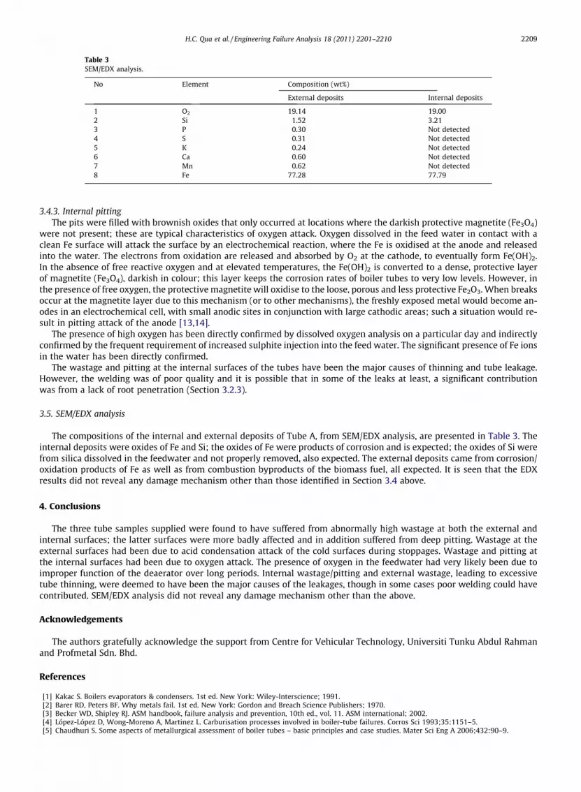
Table 3SEM/EDX analysis.
No Element Composition (wt%)
External deposits Internal deposits
1 O2 19.14 19.002 Si 1.52 3.213 P 0.30 Not detected4 S 0.31 Not detected5 K 0.24 Not detected6 Ca 0.60 Not detected7 Mn 0.62 Not detected8 Fe 77.28 77.79
H.C. Qua et al. / Engineering Failure Analysis 18 (2011) 2201–2210 2209
3.4.3. Internal pittingThe pits were filled with brownish oxides that only occurred at locations where the darkish protective magnetite (Fe3O4)
were not present; these are typical characteristics of oxygen attack. Oxygen dissolved in the feed water in contact with aclean Fe surface will attack the surface by an electrochemical reaction, where the Fe is oxidised at the anode and releasedinto the water. The electrons from oxidation are released and absorbed by O2 at the cathode, to eventually form Fe(OH)2.In the absence of free reactive oxygen and at elevated temperatures, the Fe(OH)2 is converted to a dense, protective layerof magnetite (Fe3O4), darkish in colour; this layer keeps the corrosion rates of boiler tubes to very low levels. However, inthe presence of free oxygen, the protective magnetite will oxidise to the loose, porous and less protective Fe2O3. When breaksoccur at the magnetite layer due to this mechanism (or to other mechanisms), the freshly exposed metal would become an-odes in an electrochemical cell, with small anodic sites in conjunction with large cathodic areas; such a situation would re-sult in pitting attack of the anode [13,14].
The presence of high oxygen has been directly confirmed by dissolved oxygen analysis on a particular day and indirectlyconfirmed by the frequent requirement of increased sulphite injection into the feed water. The significant presence of Fe ionsin the water has been directly confirmed.
The wastage and pitting at the internal surfaces of the tubes have been the major causes of thinning and tube leakage.However, the welding was of poor quality and it is possible that in some of the leaks at least, a significant contributionwas from a lack of root penetration (Section 3.2.3).
3.5. SEM/EDX analysis
The compositions of the internal and external deposits of Tube A, from SEM/EDX analysis, are presented in Table 3. Theinternal deposits were oxides of Fe and Si; the oxides of Fe were products of corrosion and is expected; the oxides of Si werefrom silica dissolved in the feedwater and not properly removed, also expected. The external deposits came from corrosion/oxidation products of Fe as well as from combustion byproducts of the biomass fuel, all expected. It is seen that the EDXresults did not reveal any damage mechanism other than those identified in Section 3.4 above.
4. Conclusions
The three tube samples supplied were found to have suffered from abnormally high wastage at both the external andinternal surfaces; the latter surfaces were more badly affected and in addition suffered from deep pitting. Wastage at theexternal surfaces had been due to acid condensation attack of the cold surfaces during stoppages. Wastage and pitting atthe internal surfaces had been due to oxygen attack. The presence of oxygen in the feedwater had very likely been due toimproper function of the deaerator over long periods. Internal wastage/pitting and external wastage, leading to excessivetube thinning, were deemed to have been the major causes of the leakages, though in some cases poor welding could havecontributed. SEM/EDX analysis did not reveal any damage mechanism other than the above.
Acknowledgements
The authors gratefully acknowledge the support from Centre for Vehicular Technology, Universiti Tunku Abdul Rahmanand Profmetal Sdn. Bhd.
References
[1] Kakac S. Boilers evaporators & condensers. 1st ed. New York: Wiley-Interscience; 1991.[2] Barer RD, Peters BF. Why metals fail. 1st ed. New York: Gordon and Breach Science Publishers; 1970.[3] Becker WD, Shipley RJ. ASM handbook, failure analysis and prevention, 10th ed., vol. 11. ASM international; 2002.[4] López-López D, Wong-Moreno A, Martinez L. Carburisation processes involved in boiler-tube failures. Corros Sci 1993;35:1151–5.[5] Chaudhuri S. Some aspects of metallurgical assessment of boiler tubes – basic principles and case studies. Mater Sci Eng A 2006;432:90–9.
2210 H.C. Qua et al. / Engineering Failure Analysis 18 (2011) 2201–2210
[6] Lee NH, Kim S, Choe BH, Yoon KB, Kwon D. Failure analysis of a boiler tube in USC coal power plant. Eng Fail Anal 2009;16:2031–5.[7] Ahmad J, Purbolaksono J, Beng LC, Rashid AZ, Khinani A, Ali A. Failure investigation on rear water-wall tube of boiler. Eng Fail Anal 2009;16:2325–32.[8] Saha A, Roy H, Shukla AK. Investigation into the probable cause of failure of economiser tube of a thermal power plant. J Fail Anal Preven
2010;10:187–90.[9] Dhua SK. Metallurgical investigation of failed boiler water-wall tubes received from a thermal power station. Eng Fail Anal 2010;17:1572–9.
[10] Spurr JC. Significance of copper deposits associated with a boiler tube failure. Anti-Corros Method M 1959;6(8):233–7.[11] Hutchings FR, Unterweiser PM. Failure analysis: the British Engine technical reports. Metals Park (OH): American Society for Metals; 1981.[12] Szabó A, Varga K, Németh Z, Radó K, Oravetz D, Makó KÉ, et al. Effect of a chemical decontamination procedure on the corrosion state of the heat
exchanger tubes of steam generators. Corros Sci 2006;48:2727–49.[13] Cramer SD. ASM handbook, corrosion: materials, 10th ed., vol. 13B. ASM international; 2005.[14] Trethewey KR, Chamberlain J. Corrosion for science and engineering. 2nd ed. UK: Longman; 1995.