SEPARATION OF PLASTICS FOR RECYCLING Gjergj Dodbiba and Toyohisa Fujita Department of Geosystem Engineering, Graduate school of Engineering, The University of Tokyo, Tokyo 113 - 8654, Japan E-mail: [email protected]The paper presents the basic principles of three different types of separating methods and a general guideline for choosing the most effective method for sorting plastic mixtures. It also presents the results of the tests carried out for separation of PVC, ABS and PET from different kinds of plastic mixtures in order to improve the grade of the raw input used in mechanical or feedstock recycling. INTRODUCTION According to Japan Plastics Industry Federation [1], total production of plastics amounted to more than 13.6 million tonnes in 2003, of which polyvinyl chloride (PVC), polystyrene (PS) and polyethylene (PE) represented 15.9 %, 8.5 %, and 21.8 % respectively. It has also been reported that the production of plastic products is increasing constantly year after year, as the use of plastics by machine, electronic, packaging industries, etc is spreading. The result is a rising amount of plastic wastes. The simple disposal or incineration of plastic wastes is a subject of great public concern. Therefore, mechanical or feedstock recycling is becoming a reasonable solution to the problem. Of the two methods, mechanical recycling is especially effective because it uses less energy and has a smaller environmental impact than feedstock recycling [2]. Nevertheless, the mechanical recycling is favorable alternative provided that via separation technologies a high-grade product can be achieved (i.e. the grade be higher than 96 %). The present work describes three processes (i.e. (1) air tabling; (2) triboelectric separation; and (3) combination of sink-float separation and froth flotation) for separating plastics as well as a general guideline for choosing the most effective methods, when sorting a certain type of plastic mixture. The results of the tests, carried out to separate PVC, ABS and PET from PVC/PP, ABS/PS and PET/PE mixtures respectively, are also presented to demonstrate the effectiveness of these techniques. MATERIALS Many kinds of plastics are in wide use today. Table 1 tabulates main types of plastics, showing the contact angle and the density. It also tabulates the triboelectric series (TES), in which plastics are arranged according to their polarity after frictional charging [3, 4]. For instance, when ABS and PS are rubbed against a PET surface, ABS is charged positively, while PS negatively (Table 1). Table 1 Properties of main types of plastics Polymer type Density, [kg/m 3 ] Contact angle in water, [ o ], [5] Triboelectrostatic series [3] Acrylonitrile-butadiene-styrene, ABS 1060 87.3 Positive end ( + ) Polyethylene terephthalate, PET 1350 76.5 Polystyrene, PS 1050 86.3 Polyethylene, PE 960 96.8 Polypropylene, PP 900 95.0 Polyvinyl chloride, PVC 1400 86.4 Negative end ( - ) METHODS FOR SEPARATION OF PLASTIC MIXTURES An important subject in society is now to recycle the amount of plastic wastes. As the raw mixture usually includes various kinds of waste plastics, this makes the separation an important
Transcript
SEPARATION OF PLASTICS FOR RECYCLING
Gjergj Dodbiba and Toyohisa Fujita
Department of Geosystem Engineering, Graduate school of Engineering, The University of Tokyo, Tokyo 113 - 8654, Japan
The paper presents the basic principles of three different types of separating methods and a general guideline for choosing the most effective method for sorting plastic mixtures. It also presents the results of the tests carried out for separation of PVC, ABS and PET from different kinds of plastic mixtures in order to improve the grade of the raw input used in mechanical or feedstock recycling. INTRODUCTION
According to Japan Plastics Industry Federation [1], total production of plastics amounted to more than 13.6 million tonnes in 2003, of which polyvinyl chloride (PVC), polystyrene (PS) and polyethylene (PE) represented 15.9 %, 8.5 %, and 21.8 % respectively. It has also been reported that the production of plastic products is increasing constantly year after year, as the use of plastics by machine, electronic, packaging industries, etc is spreading. The result is a rising amount of plastic wastes.
The simple disposal or incineration of plastic wastes is a subject of great public concern. Therefore, mechanical or feedstock recycling is becoming a reasonable solution to the problem. Of the two methods, mechanical recycling is especially effective because it uses less energy and has a smaller environmental impact than feedstock recycling [2]. Nevertheless, the mechanical recycling is favorable alternative provided that via separation technologies a high-grade product can be achieved (i.e. the grade be higher than 96 %).
The present work describes three processes (i.e. (1) air tabling; (2) triboelectric separation; and (3) combination of sink-float separation and froth flotation) for separating plastics as well as a general guideline for choosing the most effective methods, when sorting a certain type of plastic mixture. The results of the tests, carried out to separate PVC, ABS and PET from PVC/PP, ABS/PS and PET/PE mixtures respectively, are also presented to demonstrate the effectiveness of these techniques. MATERIALS
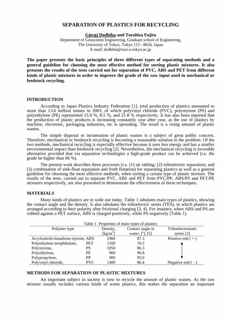
Many kinds of plastics are in wide use today. Table 1 tabulates main types of plastics, showing the contact angle and the density. It also tabulates the triboelectric series (TES), in which plastics are arranged according to their polarity after frictional charging [3, 4]. For instance, when ABS and PS are rubbed against a PET surface, ABS is charged positively, while PS negatively (Table 1).
Table 1 Properties of main types of plastics
Polymer type Density, [kg/m3]
Contact angle in water, [o], [5]
Triboelectrostatic series [3]
Acrylonitrile-butadiene-styrene, ABS 1060 87.3 Positive end ( + ) Polyethylene terephthalate, PET 1350 76.5 Polystyrene, PS 1050 86.3 Polyethylene, PE 960 96.8 Polypropylene, PP 900 95.0 Polyvinyl chloride, PVC 1400 86.4 Negative end ( - )
METHODS FOR SEPARATION OF PLASTIC MIXTURES
An important subject in society is now to recycle the amount of plastic wastes. As the raw mixture usually includes various kinds of waste plastics, this makes the separation an important
process in terms of sustainable recycling. However, separation of mixed plastics encounters many problems due to the characteristics of the feed. To deal with the problems that the industry is facing, the research work is focused primarily on designing, developing and testing a variety of separation and sorting technologies able to recover plastics from wastes, which can be re-used or re-processed to form new products. In this regard air tabling, triboelectric separation, as well as combination of sin-float separation and froth flotation can be of great help. Air Tabling
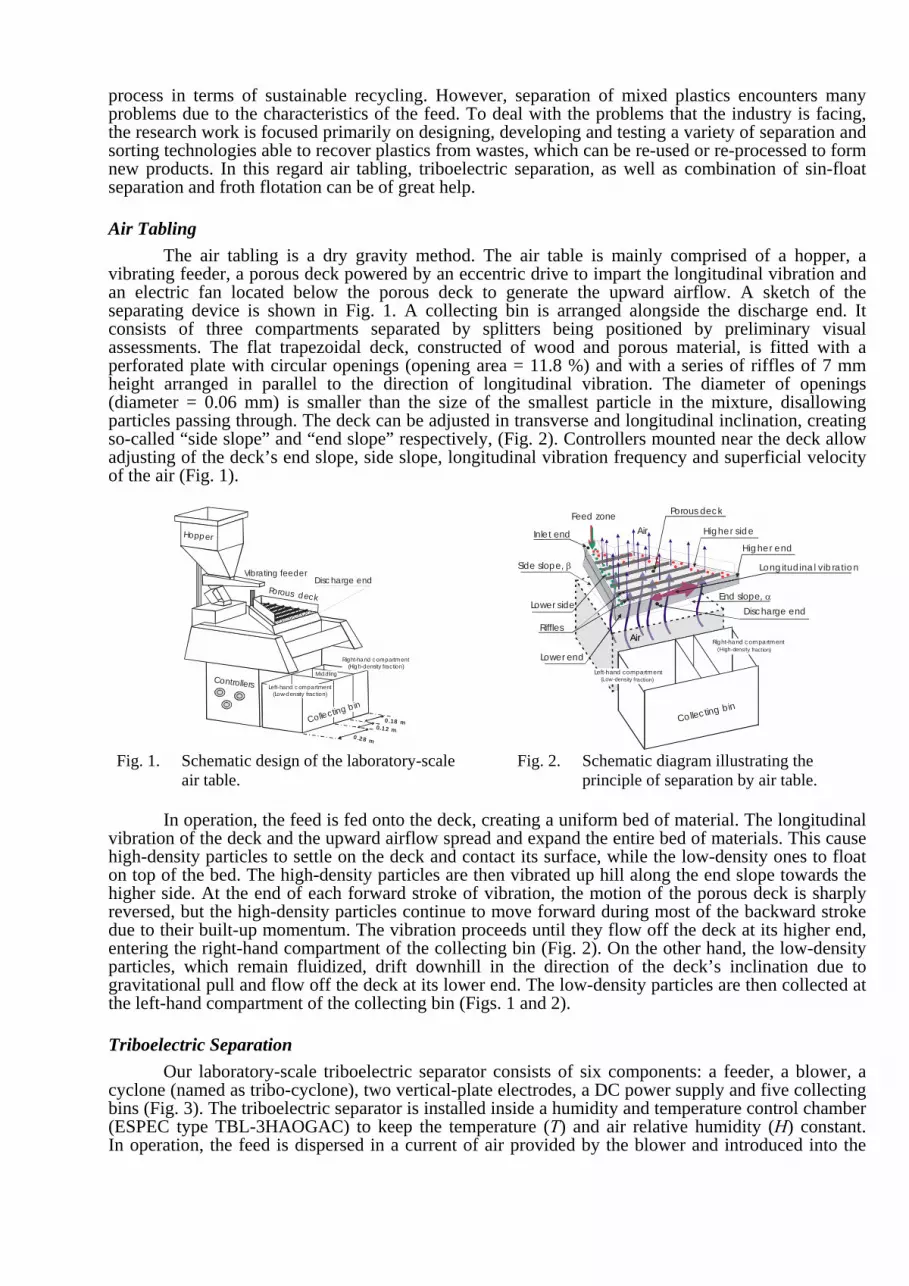
The air tabling is a dry gravity method. The air table is mainly comprised of a hopper, a vibrating feeder, a porous deck powered by an eccentric drive to impart the longitudinal vibration and an electric fan located below the porous deck to generate the upward airflow. A sketch of the separating device is shown in Fig. 1. A collecting bin is arranged alongside the discharge end. It consists of three compartments separated by splitters being positioned by preliminary visual assessments. The flat trapezoidal deck, constructed of wood and porous material, is fitted with a perforated plate with circular openings (opening area = 11.8 %) and with a series of riffles of 7 mm height arranged in parallel to the direction of longitudinal vibration. The diameter of openings (diameter = 0.06 mm) is smaller than the size of the smallest particle in the mixture, disallowing particles passing through. The deck can be adjusted in transverse and longitudinal inclination, creating so-called “side slope” and “end slope” respectively, (Fig. 2). Controllers mounted near the deck allow adjusting of the deck’s end slope, side slope, longitudinal vibration frequency and superficial velocity of the air (Fig. 1).
Hopper
Vibrating feeder
Porous deck
Controllers
0.18 m
0.28 m
Disc harge end
Left-hand c ompartment(Low-density fraction)
Right-hand compartment(High-density fraction)
Collecting b in
0.12 m
Middling
Feed zone
Side slope, β
End slope, α
Long itud ina l vib ra tio n
Discharge endLower side
Hig her sid e Air
Porous deck
RifflesAir Righ
(H
and compartment-density fraction)
Left-ha(Low
Inle t end
Lower end
Hig her end
Air Right-hand c ompartment(High-density fraction)
Collec ting bin
Left-hand compartment(Low-density fraction)
Fig. 1. Schematic design of the laboratory-scale air table.
Fig. 2. Schematic diagram illustrating the principle of separation by air table.
In operation, the feed is fed onto the deck, creating a uniform bed of material. The longitudinal
vibration of the deck and the upward airflow spread and expand the entire bed of materials. This cause high-density particles to settle on the deck and contact its surface, while the low-density ones to float on top of the bed. The high-density particles are then vibrated up hill along the end slope towards the higher side. At the end of each forward stroke of vibration, the motion of the porous deck is sharply reversed, but the high-density particles continue to move forward during most of the backward stroke due to their built-up momentum. The vibration proceeds until they flow off the deck at its higher end, entering the right-hand compartment of the collecting bin (Fig. 2). On the other hand, the low-density particles, which remain fluidized, drift downhill in the direction of the deck’s inclination due to gravitational pull and flow off the deck at its lower end. The low-density particles are then collected at the left-hand compartment of the collecting bin (Figs. 1 and 2). Triboelectric Separation
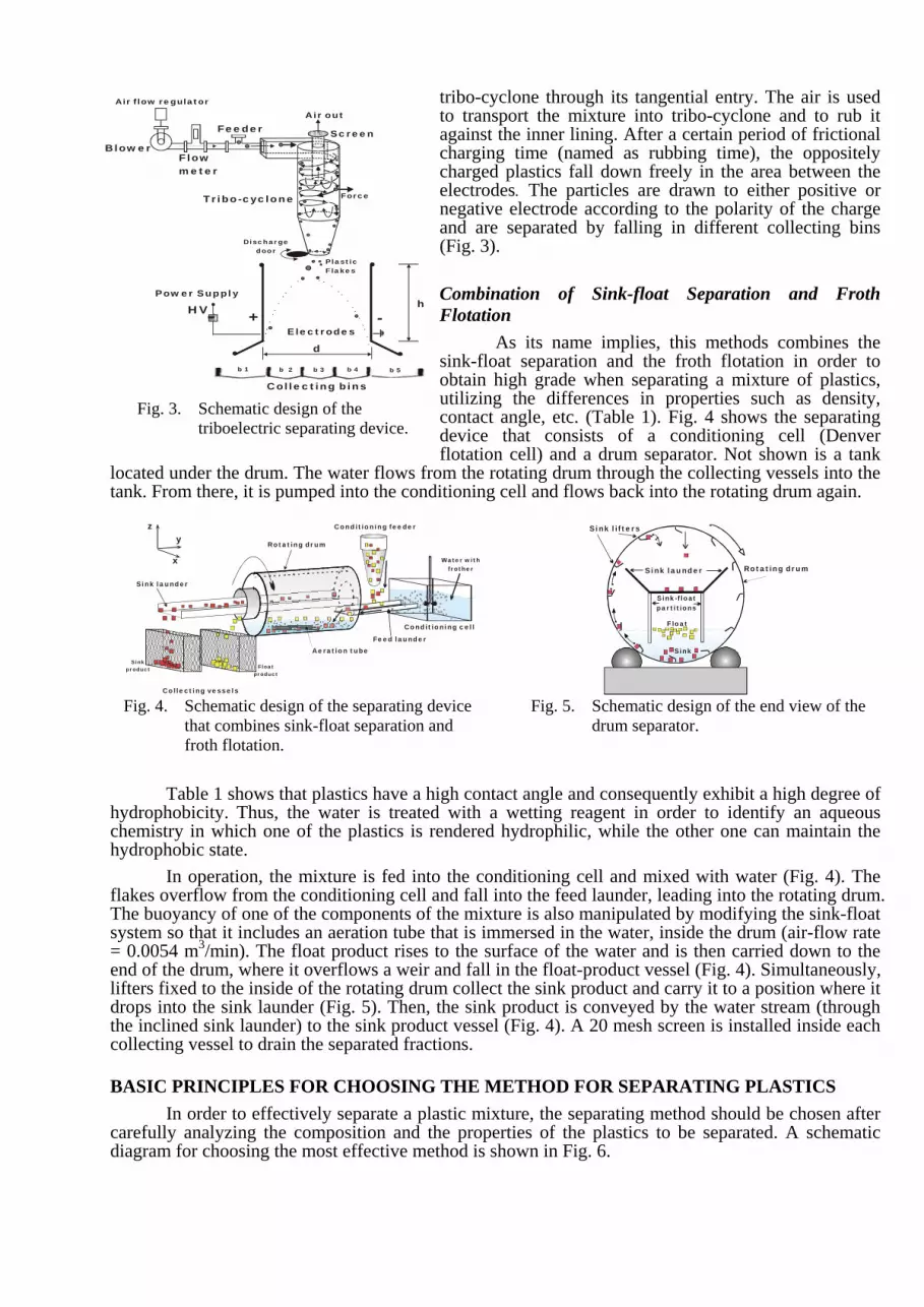
Our laboratory-scale triboelectric separator consists of six components: a feeder, a blower, a cyclone (named as tribo-cyclone), two vertical-plate electrodes, a DC power supply and five collecting bins (Fig. 3). The triboelectric separator is installed inside a humidity and temperature control chamber (ESPEC type TBL-3HAOGAC) to keep the temperature (T) and air relative humidity (H) constant. In operation, the feed is dispersed in a current of air provided by the blower and introduced into the
tribo-cyclone through its tangential entry. The air is used to transport the mixture into tribo-cyclone and to rub it against the inner lining. After a certain period of frictional charging time (named as rubbing time), the oppositely charged plastics fall down freely in the area between the electrodes. The particles are drawn to either positive or negative electrode according to the polarity of the charge and are separated by falling in different collecting bins (Fig. 3). Combination of Sink-float Separation and Froth Flotation
As its name implies, this methods combines the sink-float separation and the froth flotation in order to
btain high grade when separating a mixture of plastics, tilizing the differences in properties such as density,
loctan
Air out
PlasticFlakes
Force
Electrodes
d
hHV -+
BlowerFlow meter
Feeder
Tribo-cyclone
b 1 b 2 b 3 b 4 b 5
Discharge door
Screen
Air flow regulator
Power Supply
p
F
hychhy
flaThsys= 0enliftdrotheco BA
cardia
ou
Collecting bins
Fig. 3. Schematic design of the
contact angle, etc. (Table 1). Fig. 4 shows the separating device that consists of a conditioning cell (Denver flotation cell) and a drum separator. Not shown is a tank
ated under the drum. The water flows from the rotating drum through the collecting vessels into the k. From there, it is pumped into the conditioning cell and flows back into the rotating drum again.
triboelectric separating device.
Aeration tube
Sink launder
Collecting vessels
Sink roduct Float
product
Rotating drum
Conditioning cell
Conditioning feeder
Water with frother
x
yz
Feed launder
Float
Sink
Sink lifters
Sink launder
Sink-float partitions
Rotating drum
ig. 4. Schematic design of the separating device
that combines sink-float separation and froth flotation.
Fig. 5. Schematic design of the end view of the drum separator.
Table 1 shows that plastics have a high contact angle and consequently exhibit a high degree of
drophobicity. Thus, the water is treated with a wetting reagent in order to identify an aqueous emistry in which one of the plastics is rendered hydrophilic, while the other one can maintain the drophobic state.
In operation, the mixture is fed into the conditioning cell and mixed with water (Fig. 4). The kes overflow from the conditioning cell and fall into the feed launder, leading into the rotating drum. e buoyancy of one of the components of the mixture is also manipulated by modifying the sink-float tem so that it includes an aeration tube that is immersed in the water, inside the drum (air-flow rate .0054 m3/min). The float product rises to the surface of the water and is then carried down to the
d of the drum, where it overflows a weir and fall in the float-product vessel (Fig. 4). Simultaneously, ers fixed to the inside of the rotating drum collect the sink product and carry it to a position where it ps into the sink launder (Fig. 5). Then, the sink product is conveyed by the water stream (through inclined sink launder) to the sink product vessel (Fig. 4). A 20 mesh screen is installed inside each
llecting vessel to drain the separated fractions.
SIC PRINCIPLES FOR CHOOSING THE METHOD FOR SEPARATING PLASTICS In order to effectively separate a plastic mixture, the separating method should be chosen after
efully analyzing the composition and the properties of the plastics to be separated. A schematic gram for choosing the most effective method is shown in Fig. 6.
Fig. 6 shows that if the difference between the densities of plastics to be separated is more than 450 kg/m3, then the air tabling is employed, otherwise the triboelectric separation or the combination of sink-float separation and froth flotation is considered. Fig. 6 also shows that if the concentration criterion C is less than 2.5 [6], then triboelectric separation is the only alternative; otherwise a selection between the triboelectric separation and the combination of sink-float separation and froth flotation should be made based on the characteristics of each method. Here it should be note that although wet separation techniques (including sink-float separation and froth flotation) provide adequate recoveries, separation in dry state may be of environmental benefits, since some requirements associated with wet separating methods in general such as (1) chemical pretreatment of materials, (2) treatment of water from the process for reuse or discharge, and (3) dewatering or drying the
Fig. 6. Schematic diagram for choosing the Product 1 Product 2 Product 1 Product
mixture after separation can be avoided. Typical examples for separation of various
plastic mixtures with detailed processing procedure are described in the following sections. The tests
were carried out on 50% / 50% artificial mixtures of PVC/PP, ABS/PS and PET/PE. Size-reduction of plastics was carried out in a shredder provided by Nissui Kako Co. LTD of Japan (Nissui Scutter, type: SA - 22). The shredded mixtures were then classified by their size using conventional sieving. Plastic flakes of irregular shapes and 2.38 to 3.36 mm in size were used throughout the experimental work. The difference in color between plastic types allowed easy hand-sorting and visual analysis of each product discharged from the separating device. No special treatment of the feed was done prior to the experiment. The grade and the recovery of the products were calculated based on the mass of the input fraction (i.e. feed), which entered the separating device (Fig. 6). Case 1: Removal Of PVC From PVC/PP Mixture By Means Of Air Table
The removal of polyvinyl chloride (PVC) is especially important for refuse derived fuel systems (RDF) to reduce dioxin. Hence, removal of PVC from other plastics should be carried out in advance. In the present work, the separation of PVC from polypropylene (PP) was performed by means of the air table (Figs. 1 and 2), which is effective in sorting wastes [7] and in applications where the water is at premium [6].
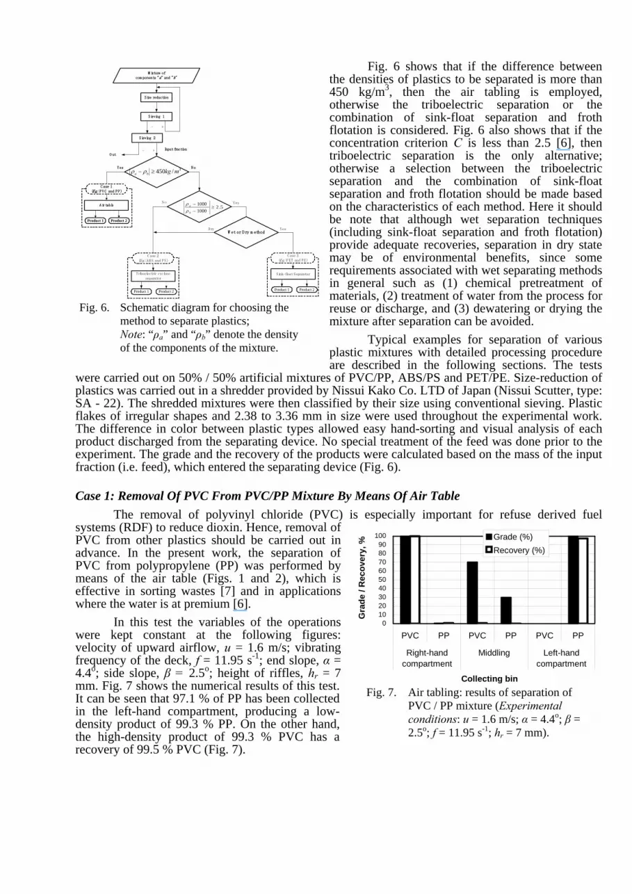
In this test the variables of the operations were kept constant at the following figures: velocity of upward airflow, u = 1.6 m/s; vibrating frequency of the deck, f = 11.95 s-1; end slope, α = 4.4o; side slope, β = 2.5o; height of riffles, hr = 7 mm. Fig. 7 shows the numerical results of this test. It can be seen that 97.1 % of PP has been collected in the left-hand compartment, producing a low-density product of 99.3 % PP. On the other hand, the high-density product of 99.3 % PVC has a recovery of 99.5 % PVC (Fig. 7).
method to separate plastics; Note: “ρa” and “ρb” denote the density of the components of the mixture.
Fig. 7. Air tabling: results of separation of PVC / PP mixture (Experimental conditions: u = 1.6 m/s; α = 4.4o; β = 2.5o; f = 11.95 s-1; hr = 7 mm).
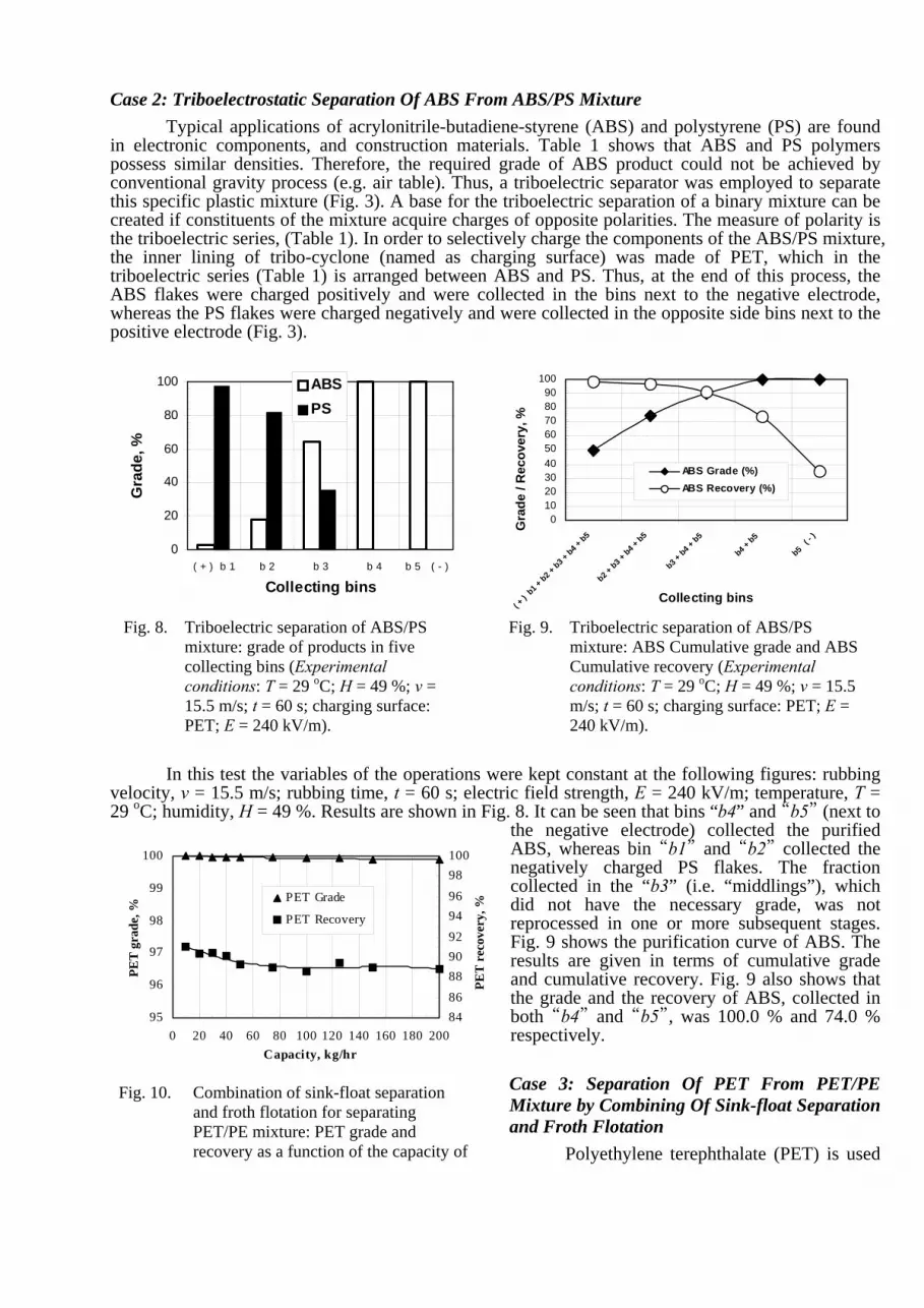
Case 2: Triboelectrostatic Separation Of ABS From ABS/PS Mixture Typical applications of acrylonitrile-butadiene-styrene (ABS) and polystyrene (PS) are found
in electronic components, and construction materials. Table 1 shows that ABS and PS polymers possess similar densities. Therefore, the required grade of ABS product could not be achieved by conventional gravity process (e.g. air table). Thus, a triboelectric separator was employed to separate this specific plastic mixture (Fig. 3). A base for the triboelectric separation of a binary mixture can be created if constituents of the mixture acquire charges of opposite polarities. The measure of polarity is the triboelectric series, (Table 1). In order to selectively charge the components of the ABS/PS mixture, the inner lining of tribo-cyclone (named as charging surface) was made of PET, which in the triboelectric series (Table 1) is arranged between ABS and PS. Thus, at the end of this process, the ABS flakes were charged positively and were collected in the bins next to the negative electrode, whereas the PS flakes were charged negatively and were collected in the opposite side bins next to the positive electrode (Fig. 3).
0
20
40
60
80
100
( + ) b 1 b 2 b 3 b 4 b 5 ( - )
Collecting bins
Gra
de, %
ABSPS
0102030405060708090
100
( + )
b1 + b2 +
b3 + b4 +
b5
b2 + b3 +
b4 + b5
b3 + b4 +
b5
b4 + b5
b5 ( -
)
Collecting bins
Gra
de /
Rec
over
y, %
ABS Grade (%)ABS Recovery (%)
Fig. 8. Triboelectric separation of ABS/PS
mixture: grade of products in five collecting bins (Experimental conditions: T = 29 oC; H = 49 %; v = 15.5 m/s; t = 60 s; charging surface: PET; E = 240 kV/m).
Fig. 9. Triboelectric separation of ABS/PS mixture: ABS Cumulative grade and ABS Cumulative recovery (Experimental conditions: T = 29 oC; H = 49 %; v = 15.5 m/s; t = 60 s; charging surface: PET; E = 240 kV/m).
In this test the variables of the operations were kept constant at the following figures: rubbing
velocity, v = 15.5 m/s; rubbing time, t = 60 s; electric field strength, E = 240 kV/m; temperature, T = 29 oC; humidity, H = 49 %. Results are shown in Fig. 8. It can be seen that bins “b4” and “b5” (next to
the negative electrode) collected the purified ABS, whereas bin “b1” and “b2” collected the negatively charged PS flakes. The fraction collected in the “b3” (i.e. “middlings”), which did not have the necessary grade, was not reprocessed in one or more subsequent stages. Fig. 9 shows the purification curve of ABS. The results are given in terms of cumulative grade and cumulative recovery. Fig. 9 also shows that the grade and the recovery of ABS, collected in both “b4” and “b5”, was 100.0 % and 74.0 % respectively.
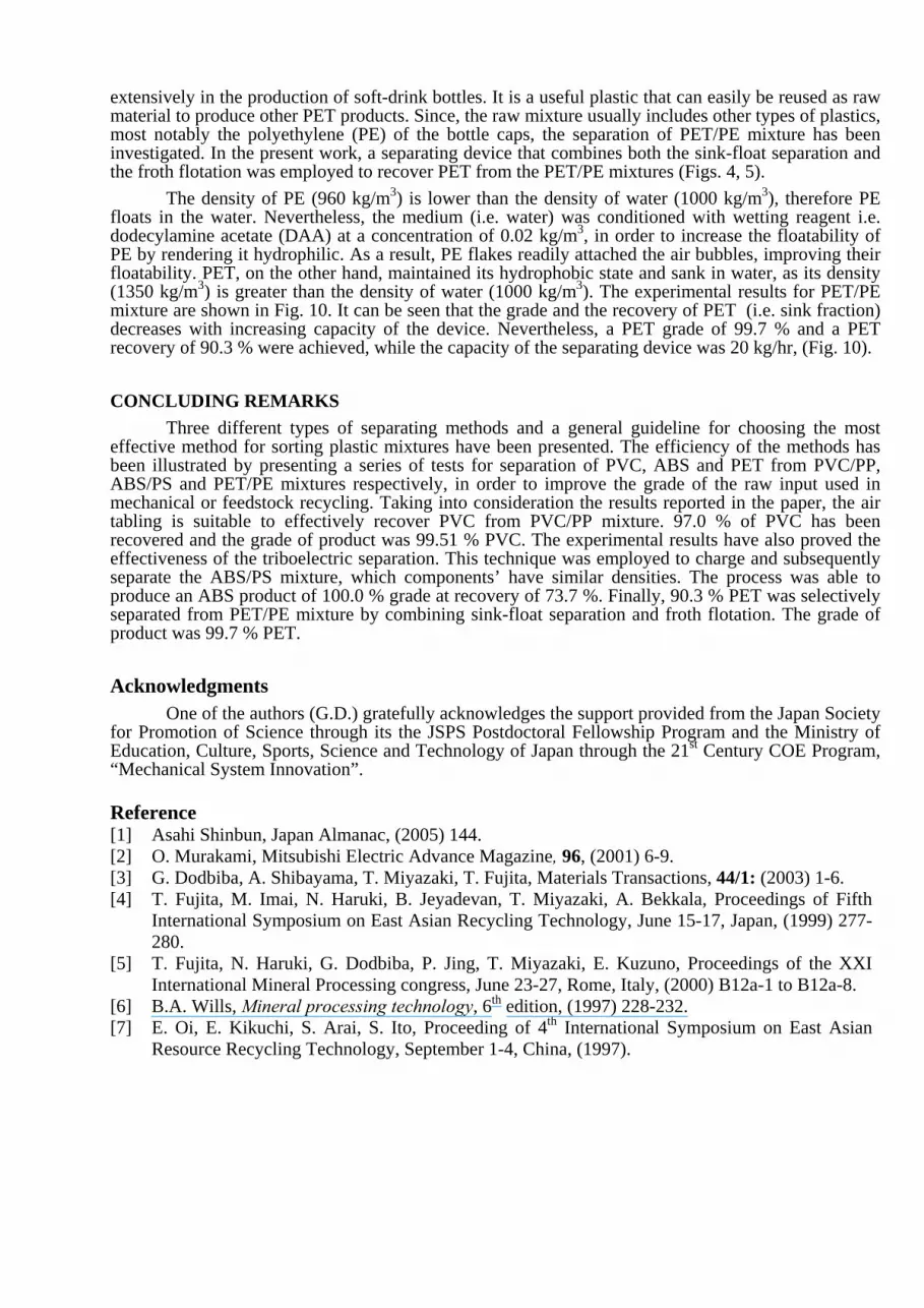
Case 3: Separation Of PET From PET/PE Mixture by Combining Of Sink-float Separation and Froth Flotation
Fig. 10. Combination of sink-float separation and froth flotation for separating PET/PE mixture: PET grade and recovery as a function of the capacity of Polyethylene terephthalate (PET) is used
extensively in the production of soft-drink bottles. It is a useful plastic that can easily be reused as raw material to produce other PET products. Since, the raw mixture usually includes other types of plastics, most notably the polyethylene (PE) of the bottle caps, the separation of PET/PE mixture has been investigated. In the present work, a separating device that combines both the sink-float separation and the froth flotation was employed to recover PET from the PET/PE mixtures (Figs. 4, 5).
The density of PE (960 kg/m3) is lower than the density of water (1000 kg/m3), therefore PE floats in the water. Nevertheless, the medium (i.e. water) was conditioned with wetting reagent i.e. dodecylamine acetate (DAA) at a concentration of 0.02 kg/m3, in order to increase the floatability of PE by rendering it hydrophilic. As a result, PE flakes readily attached the air bubbles, improving their floatability. PET, on the other hand, maintained its hydrophobic state and sank in water, as its density (1350 kg/m3) is greater than the density of water (1000 kg/m3). The experimental results for PET/PE mixture are shown in Fig. 10. It can be seen that the grade and the recovery of PET (i.e. sink fraction) decreases with increasing capacity of the device. Nevertheless, a PET grade of 99.7 % and a PET recovery of 90.3 % were achieved, while the capacity of the separating device was 20 kg/hr, (Fig. 10). CONCLUDING REMARKS
Three different types of separating methods and a general guideline for choosing the most effective method for sorting plastic mixtures have been presented. The efficiency of the methods has been illustrated by presenting a series of tests for separation of PVC, ABS and PET from PVC/PP, ABS/PS and PET/PE mixtures respectively, in order to improve the grade of the raw input used in mechanical or feedstock recycling. Taking into consideration the results reported in the paper, the air tabling is suitable to effectively recover PVC from PVC/PP mixture. 97.0 % of PVC has been recovered and the grade of product was 99.51 % PVC. The experimental results have also proved the effectiveness of the triboelectric separation. This technique was employed to charge and subsequently separate the ABS/PS mixture, which components’ have similar densities. The process was able to produce an ABS product of 100.0 % grade at recovery of 73.7 %. Finally, 90.3 % PET was selectively separated from PET/PE mixture by combining sink-float separation and froth flotation. The grade of product was 99.7 % PET. Acknowledgments
One of the authors (G.D.) gratefully acknowledges the support provided from the Japan Society for Promotion of Science through its the JSPS Postdoctoral Fellowship Program and the Ministry of Education, Culture, Sports, Science and Technology of Japan through the 21st Century COE Program, “Mechanical System Innovation”. Reference [1] Asahi Shinbun, Japan Almanac, (2005) 144. [2] O. Murakami, Mitsubishi Electric Advance Magazine, 96, (2001) 6-9. [3] G. Dodbiba, A. Shibayama, T. Miyazaki, T. Fujita, Materials Transactions, 44/1: (2003) 1-6. [4] T. Fujita, M. Imai, N. Haruki, B. Jeyadevan, T. Miyazaki, A. Bekkala, Proceedings of Fifth
International Symposium on East Asian Recycling Technology, June 15-17, Japan, (1999) 277-280.
[5] T. Fujita, N. Haruki, G. Dodbiba, P. Jing, T. Miyazaki, E. Kuzuno, Proceedings of the XXI International Mineral Processing congress, June 23-27, Rome, Italy, (2000) B12a-1 to B12a-8.
[6] B.A. Wills, Mineral processing technology, 6th edition, (1997) 228-232. [7] E. Oi, E. Kikuchi, S. Arai, S. Ito, Proceeding of 4th International Symposium on East Asian
Resource Recycling Technology, September 1-4, China, (1997).