Compurerized Medrcal Imaging and Graphm Vol. Il. No. I, pp. I-I I, 1993 Printed in the U.S.A All rights reser?ed. 0895-61 I l/93 $6.00 + .W Copyright 0 1993 Pergamon Press Ltd. IMPLEMENTATION OF A LARGE-SCALE PICTURE ARCHIVING AND COMMUNICATION SYSTEM H. K. Huang,*+ Ricky K. Taira, Shyh-Liang Lou,+ Albert WK. Wang,+ Claudine Breant, Bruce K.T. Ho, Keh-Shih Chuang, Brent K. Stewart, Katherine Andriole,+ Raymond Tecotzky,* Todd Bazzill,+ Sandy L. Eldredge, James Tagawa, Zoran Barbaric, M. Ines Boechat, Theodore Hall, John Bentson, and Hooshang Kangarloo Department of Radiological Sciences, University of California, Los Angeles, CA 90024- 172 I (Received 9 July 1992; revised 27 October 1992) Abstract-This paper describes the implementation of a large-scale picture archiving and communication system (PACS) in a clinical environment. The system consists of a PACS infrastructure, composed of a PACS controller, a database management system, communication networks, and optical disk archive. It connects to three MR units, four CT scanners, three computed radiography systems, and two laser film digitizers. Seven display stations are on line 24 h/day, 7 days/wk in genitourinary radiology (2K), pediatric radiology in-patient (1K and 2K) and out- patient (2K), neuroradiology (2K), pediatric ICU (lK), coronary care unit (lK), and one laser film printing station. The PACS is integrated with the hospital information system and the radiology information system. The system has been in operation since February 1992. We have integrated this PACS as a clinical component in daily radiology practice. It archives an average of 2.0-gigabyte image data per workday. A 3-mo system performance of various components are tabulated. The deployment of this large-scale PACS signifies a milestone in our PACS research and development effort. Radiologists, fellows, residents, and clinicians use it for case review, conferences, and occasionally for primary diagnosis. With this huge-scale PACS in place, it will allow us to investigate the two critical issues raised when PACS research first started 10 yrs ago: system performance and cost effectiveness between a digital-based and a film-based system. Key Words: Digital radiology. Picture archiving and communication system. Display station, Digital network INTRODU(XION There are two methods to implement a picture archiv- ing and communication system (PACS). One method is to purchase a system from the manufacturer and the other is to develop your own. We started the research and development of PACS in 1982. Because there was no PACS available in the market then, we chose to develop our own. During the past 10 yrs, we went through four important phases. Phase I was the estab- lishment of the image processing laboratory, and ini- tiation of the resident rotation, and the graduate student training program in medical imaging from 1983 to 1986 ( 1, 2). This phase provided an incubation period for future growth. During this phase we had the op- portunity to experiment with various equipment, es- tablished contacts with manufacturers, as well as pro- * Correspondence should be addressed to Dr. H. K. Huang, Department of Radiology, UCSF Medical Center-Moffit Hospital, 505 Parnassus Avenue, Box 0628, San Francisco, CA 94143-0628. t Current address: Same as H. K. Huang. $ Current address: Fuji Medical Systems, 90 Viaduct Rd., P.O. Box 4960. Stamford, CT 06907. vided basic imaging science training for staff. Phase II from 1986 to 1989 was to test the concept of PACS by implementing three PACS modules in pediatric ra- diology (3), coronary care unit (4), and Neuroradiology (5). The clinical results derived from these three mod- ules allowed us to design and implement an infrastruc- ture which is the foundation of a digital-based radiology operation (6). The completion of the infrastructure in 1990-l 99 1 represented the Phase III effort (7,8). Phase IV was the total system integration and the release of the system for clinical evaluation in January, 1992. The progress from Phase I to Phase III had been doc- umented in detail ( l-8). This paper describes the total system integration and how we migrated the PACS from the research laboratory to the clinical environ- ment. SYSTEM DESCRIPTION The current PACS consists of several major com- ponents: the infrastructure, connection of image ac- quisition devices to the infrastructure, image display
Transcript
Compurerized Medrcal Imaging and Graphm Vol. Il. No. I, pp. I-I I, 1993 Printed in the U.S.A All rights reser?ed.
IMPLEMENTATION OF A LARGE-SCALE PICTURE ARCHIVING AND COMMUNICATION SYSTEM
H. K. Huang,*+ Ricky K. Taira, Shyh-Liang Lou,+ Albert WK. Wang,+ Claudine Breant, Bruce K.T. Ho, Keh-Shih Chuang, Brent K. Stewart,
Katherine Andriole,+ Raymond Tecotzky,* Todd Bazzill,+ Sandy L. Eldredge, James Tagawa, Zoran Barbaric, M. Ines Boechat, Theodore Hall, John Bentson,
and Hooshang Kangarloo Department of Radiological Sciences, University of California, Los Angeles, CA 90024- 172 I
(Received 9 July 1992; revised 27 October 1992)
Abstract-This paper describes the implementation of a large-scale picture archiving and communication system (PACS) in a clinical environment. The system consists of a PACS infrastructure, composed of a PACS controller, a database management system, communication networks, and optical disk archive. It connects to three MR units, four CT scanners, three computed radiography systems, and two laser film digitizers. Seven display stations are on line 24 h/day, 7 days/wk in genitourinary radiology (2K), pediatric radiology in-patient (1K and 2K) and out- patient (2K), neuroradiology (2K), pediatric ICU (lK), coronary care unit (lK), and one laser film printing station. The PACS is integrated with the hospital information system and the radiology information system. The system has been in operation since February 1992. We have integrated this PACS as a clinical component in daily radiology practice. It archives an average of 2.0-gigabyte image data per workday. A 3-mo system performance of various components are tabulated. The deployment of this large-scale PACS signifies a milestone in our PACS research and development effort. Radiologists, fellows, residents, and clinicians use it for case review, conferences, and occasionally for primary diagnosis. With this huge-scale PACS in place, it will allow us to investigate the two critical issues raised when PACS research first started 10 yrs ago: system performance and cost effectiveness between a digital-based and a film-based system.
Key Words: Digital radiology. Picture archiving and communication system. Display station, Digital network
INTRODU(XION
There are two methods to implement a picture archiv- ing and communication system (PACS). One method is to purchase a system from the manufacturer and the other is to develop your own. We started the research and development of PACS in 1982. Because there was no PACS available in the market then, we chose to develop our own. During the past 10 yrs, we went through four important phases. Phase I was the estab- lishment of the image processing laboratory, and ini- tiation of the resident rotation, and the graduate student training program in medical imaging from 1983 to 1986 ( 1, 2). This phase provided an incubation period for future growth. During this phase we had the op- portunity to experiment with various equipment, es- tablished contacts with manufacturers, as well as pro-
* Correspondence should be addressed to Dr. H. K. Huang, Department of Radiology, UCSF Medical Center-Moffit Hospital, 505 Parnassus Avenue, Box 0628, San Francisco, CA 94143-0628.
t Current address: Same as H. K. Huang. $ Current address: Fuji Medical Systems, 90 Viaduct Rd., P.O.
Box 4960. Stamford, CT 06907.
vided basic imaging science training for staff. Phase II from 1986 to 1989 was to test the concept of PACS by implementing three PACS modules in pediatric ra- diology (3), coronary care unit (4), and Neuroradiology (5). The clinical results derived from these three mod- ules allowed us to design and implement an infrastruc- ture which is the foundation of a digital-based radiology operation (6). The completion of the infrastructure in 1990-l 99 1 represented the Phase III effort (7,8). Phase IV was the total system integration and the release of the system for clinical evaluation in January, 1992. The progress from Phase I to Phase III had been doc- umented in detail ( l-8). This paper describes the total system integration and how we migrated the PACS from the research laboratory to the clinical environ- ment.
SYSTEM DESCRIPTION
The current PACS consists of several major com- ponents: the infrastructure, connection of image ac- quisition devices to the infrastructure, image display
N
Glo
bei E
tfm
rnet
FDD
I To
Med
ical
Pla
za
- ----
C
ON
TRO
LLE
R
UC
LA P
AC
S N
etw
ork:
Cen
ter
for
Hea
lth S
cien
ces
and
Rem
ote
MR
Site
A
w
To C
HS
FD
DI
u% a
PA
CS
C
ON
TRO
LLE
R
0 2(1
1 I
d -
Ultr
aNet
- -
UC
LA
PA
CS
N
etw
ork:
M
edic
al
Pla
za
B
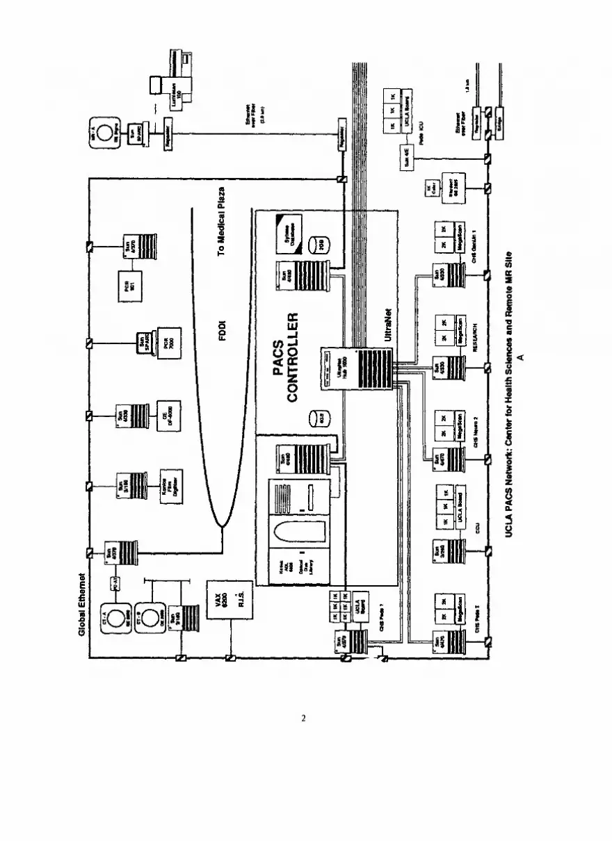
Fig.
1.
The
PA
CS
infr
astru
ctur
e de
sign
at
UC
LA.
The
desi
gn
emph
asiz
es
syst
em
relia
bilit
y.
The
hard
war
e is
dis
tribu
ted
alm
ost
even
ly
in
two
build
ings
w
ith
sim
ilar
com
pone
nts
for
hard
war
e re
dund
ancy
. Th
e th
ree-
tiere
d co
mm
unic
atio
n ne
twor
k m
inim
izes
po
tent
ial
netw
ork
failu
re.
The
mirr
ored
da
taba
se
in t
wo
SUN
SP
AR
Cse
rver
49
0 co
mpu
ters
av
oids
lo
ss o
f da
ta
due
to a
dis
k fa
ilure
in
the
da
taba
se
mac
hine
. C
onne
ctio
ns
to i
mag
e ac
quis
ition
de
vice
s an
d di
spla
y st
atio
ns
may
ch
ange
th
roug
h tim
e du
e to
sys
tem
ev
olut
ion.
Th
e ba
sic
infr
astru
ctur
e de
sign
sh
ould
re
mai
n in
tact
. D
otte
d lin
e:
futu
re
expa
nsio
n.
(A)
The
Cen
ter
for
Hea
lth
Scie
nces
; (B
) Th
e M
edic
al
Plaz
a.
Dot
ted
lines
: Pl
anni
ng.
4 Computerized Medical Imaging and Graphics JanuaryFebruaq/l993, Volume 17, Number I
stations, and integration of hospital information system (HIS), radiology information system (RIS), and PACS.
Infrastructure We described the PACS infrastructure design
concept in reference (7). Figure 1 summarizes the overall architecture of the infrastructure in our de- partment which has been in operation since October 199 1. The infrastructure emphasizes system standard- ization, open architecture, reliability, and security.
Four CT scanners (three GE 9800 Highlight Ad- vantage, one GE 9800 Quick, General Electric Medical Systems, Milwaukee, WI), Three 1.5 T MR scanners (GE Signa), Three computed radiography units (two PCR 7000, one PCR 901, Philips Medical Systems, Inc., Shel- ton, CN), Three laser film digitizers (two Lumiscan 100, Lu- misys, Sunnyvale, CA; one KFDR-S, Konica, Tokyo, Japan).
The infrastructure uses industrial standards whenever possible. These include UNIX operating system, TCP/IP communication protocol, SQL data- base query language, ACR-NEMA standard, C pro- gramming language, X-window user interface, and ASCII text presentation for message passing [see (7) for definitions]. We used translators to connect com- ponents, which do not use these standards. A translator is a software program which translates programs written for a given computer system to the other and is a part of the open architecture design. During the implemen- tation, we collaborated with various manufacturers to write the translators and to incorporate them into the infrastructure. An example is the integration of the RIS, the HIS, and the PACS, which will be described in a latter section.
The CT and MR scanners are connected to the infrastructure using the GE Genesis Communication protocol; the software was implemented with the as- sistance of GE engineers (10). The PCR-901 and the Konica laser scanner interfaces are based on the DR ll- W connection method (11). The Lumisys scanners and the PCR-7000s connections are through the Ethernet communication protocol (11). Images obtained from the MR and CR are transmitted to the storage device in the infrastructure automatically without human in- tervention. In the case of CT, the CT operator has to push the send button at the console to initiate the transmission. For the laser film digitizers, the operator has to input patient’s information manually during the digitization procedure.
In system reliability, we stress data integrity and minimization of system downtime. In order to preserve data integrity, any image acquired by an acquisition device connected to the infrastructure is first verified and categorized, and then archived in the optical disk library. The image database has a mirrored architec- ture; a single disk crash will not effect the data integrity. During the past 10 months, this component has achieved 100% reliability (8).
Any new image acquisition device can be con- nected to the infrastructure through the open archi- tecture design. As an example, the fourth CT GE 9800 Highlight Advantage scanner was installed in Decem- ber 199 1. Using the same software package and com- munication protocol for the other scanners, it took us less than 3 wk to successfully connect this new scanner to the infrastructure.
To minimize the system downtime, Fig. 1 illus- trates the hardware redundancy that includes a dual PACS controller design, each of which locates at a dif- ferent building, a three-tiered communication network protocol for alternative image routing (9) and two un- interrupted power supplies, one for each PACS con- troller, for automatic continuation of system operations during a power outage (7).
The infrastructure has been designed and imple- mented as a dynamic modular structure that can be upgraded with new components as future technology continues to evolve. The infrastructure will not become obsolete.
In addition to the digital network shown in Fig. 1, the four CT and three MR scanners are also con- nected together through a fiber optic video broadband communication system. The video network consists of baseband fiber optic transmitters and receivers, a mul- tiplexing headend, and broadband fiber optic trans- mitters, and 14 receivers and monitors distributed throughout the department. A radiologist can use any of these 14 receivers to view a patient’s CT/MR image in real time by selecting the proper channel assigned to the scanner, and uses the telephone to communicate with the technologist at the scanner room to monitor and to review the examination (12).
Display stations
Image acquisition As of February 1992, the following image acqui-
sition devices have been connected to the infrastruc- ture.
Eight display stations are available for clinical use: four 2K (two monitors) stations located at genitouri- nary radiology, pediatric in-patient ( 13), pediatric out- patient, and neuroradiology; three 1K stations at pe- diatric radiology in-patient (six monitors), pediatric
Large-scale picture archiving and communication system ??H. K. HUANG et al. 5
intensive care unit (three monitors), and coronary care unit (three monitors), and one general purpose laser film printing station.
Images from the current examination and one historical examination based on a correlation algorithm are sent from the PACS controller to the proper display station after the completion of an examination (14). The interfaces between the HIS, RIS, and PACS allow the PACS to acquire relevant information about the patient to determine where these images should be sent and what historical images should accompany the cur- rent images. Only neuroradiology examinations are sent to the neuroradiology station, and so forth. How- ever, images of any CT, MR, or computed radiography examination from any patient can be retrieved Born the optical disk library at any 2K or 1 K display station.
The 1K station is based on the SUN SPARC 4E computer with a 32 MB image memory board and a 1.3 GBytes magnetic disk (SUN Microsystems, Moun- tain View, CA). We designed a three-channel display controller allowing images to be displayed in three 2 1’ diagonal 1 K portrait mode monitors (15) (Image Sys- terns, Hopkins, MN). A 1K image from the disk can be displayed in 1 s. The 2K station is based on the SUN SPARCserver 470 computer and two 2 1’ diagonal 2K portrait mode monitors (UHR-4820P MegaScan display system, AVP, Littleton, MA). Each 2K station has a parallel transfer disk with 2.6 GByte formatted storage which can display a 2048 X 2048 X 12-bit image in 1.5 s (Storage Concepts, Irvine, CA). All software programs were written in C programming language, UNIX operating system, and X-window user interface. Table 1 lists the software functions currently available
for both the 1 K and 2K stations. Both types of stations use a mouse (or track ball) and an eight-dial panel for the user interface. The keyboard is used only when a retrieval function, which requires the patient ID, is performed. Fii 2 and 3 show the 1K and 2K sta- tions.
Integration of databases Two common methods can be used to interface
disparate database: query and trigger. We selected to use the trigger mechanism because it is easier to im- plement. The PACS uses the Sybase, a relational data- base management system, (Sybase Inc., Emeryville, CA)tomanagetheimagesImagesarearchivedintwo ADL 6800 optical disk Iiies (Kodak, Rochester, NY) using the UCLA format which is compatible with the ACR/NEMA format (16). The PACS database is in- with the RIS (MAXFILE, Dimensional Medicine, Inc., Minneapolis, MN) which, in turn, is inter&ed with the hospital’s HIS (IBM, York Town, NY). When the HIS database receives new information relating to patient admission, transfer, and discharge, it triggem the interfaces between the HIS and the RIS, as well as between the RIS and the PACS (Fig. 4). This information is used to update the PACS database. When the radiologist approves a report at the RIS, the RIS sends procedure complete and approved report data to the PACS (Fig. 5). Diagnostic reports are ap pended to the patient directory in the PACS database. At the PACS display station, images as well as reports can be recalled. The hospital Medical Center Computer Service personnel worked with Dimensional Medicine, Inc. for the integration of HIS and RIS. The scientific
TABLE 1. Software functions available for the 1 K and 2K display stations
Function Description
Directory Patient directory Study list
Display Screen reconfiguration
Monitor selection Display
Image Manipulation Dials LUT Cine Rotation Negative
Utilities Image discharge Library search Report
Measurement Measurements
Name, ID, age, sex, date of current exam Type of exam, anatomical area, date studies taken
Reconfigure each screen for the convenience of image display (2K only)
Left, middle ( 1K only), right Display images according to screen configuration and monitor selected
Brightness, contrast, zoom, and scroll Predefined look up tables (bone, soft tissue, brain, etc.) Double or triple tine on two or three monitors for CT and MR images Rotate an image at 90” increment, or flip Reverse grey scale
Delete images of discharged patients, a privileged operation Retrieve historical examinations (requires keyboard operation) Retrieve reports from RIS
Linear and region of interest
6 Computerized Medical Imaging and Graphics January-February/ 1993, Volume 17, Number I
Fig. 2. The 1K display station at an ICU. It consists of three progressive scan portrait mode monitors (P), a text monitor for patient and study information (T), an eight-dial panel (D), and a mouse (M) for image processing.
The keyboard is for retrieving historical examinations.
staff members in the department integrated the RIS PACS to send data back to RIS except system com- and PACS. mands, queries, and acknowledgments.
Because the RIS and PACS use two different com- puter systems, interfacing these two databases requires certain procedures. In the case of RIS, it uses a VAX 6200 computer, the VMS operating system [Digital Equipment Corporation, Boston, MA) and the MUMPS language (Massachusetts General Hospital Utility Multi-Programming System ( 17)]. On the other hand, PACS uses SUN Computers, the UNIX oper- ating system, and Sybase, which uses a structured query language (SQL) and a relational data model. In order to interface these two systems, we used the standard TCP/IP (transmission control protocol/intemet pro- tocol) communication protocol, a standard text data format, and wrote a language translator from SQL to MUMPS and vice versa. With these arrangements, we are able to send PACS queries to RIS, receive relevant patient text information and diagnostic reports from RIS and, hence, HIS, and append them to the PACS database (18). The current interface does not allow
CLINICAL IMPLEMENTATION AND OPERATION
Implementation We developed the software and assembled the first
2K and the first 1 K display station in the research lab- oratory in July 199 1. During this time radiologists from various sections were invited to comment and make suggestions. The 2K station was moved to the geni- tourinary radiology section in October for clinical evaluation for two reasons: its lower volume of ex- aminations and the enthusiasm of the section chief. The 1K station was moved to the pediatric ICU in December. Valuable feedbacks including deletion of nondesirable features and addition of software for ease of use were suggested. A new 2K system was redesigned to replace the existing one. The software of the 1K station was modified significantly. Both stations were replaced in January 1992. Additional 2K and 1K sta-
Large-scale picture archiving and communication system ??H. K. HUANG et al. I
Fig. 3. A basic PACS station in a specialty viewing room. This picture was taken at the genitout-inary viewing room. (A) The fiber optic broadband receiver and monitor tuning to a specific channel. (B) The display station with two 2K progressive scan portrait (P) mode monitors and a text monitor (T), with an eight-dial panel (D) and a mouse (M) for image processing. The keyboard is used to type in a patient’s name for retrieving historical
examinations. (C) The RIS terminal.
tions based on the new versions were assembled in the research laboratory. They were then deployed to the following clinical areas: pediatric radiology in-patient reading room (2K and 1K); neuroradiology (2K), pe-
diatric radiology out-patient (2K), pediatric intensive care unit (1 K), coronary care unit (1 K), a general film printing station with a laser film printer (KELP, Kodak, Rochester, NY). All stations were completely installed
film patient movement
and medical administrative _
patient admission
A
Fig. 4. Interfacing between the hospital information system (HIS) and the radiology information system (RIS). The HIS transmits patient admission, transfer, and discharge to the RIS.
8 Computerized Medical Imaging and Graphics January_Fehruary/l993, Volume 17, Number I
RIS procedure report report scheduling arrival
report complete dictated transcribed
-0-o approved
.-. L 1
HIS /
insert procedure description
PACS b&ertpatient demographics CZlSf!
. . ??-
. . patient patient paGent
admission transfer discharge
Fs 5. Interfacing between the HIS, IUS, and PACS. The RIS transmits patient admission, transfer, and discharge as well as procedure complete and approved report data to the PACS.
in February, 1992. We had an open house for all the participants during the annual meeting of the Inter- national Society for Optical Engineering, Medical Im- aging VI @PIE), February 23 to 27.
Operation Since March, the complete system has been in op-
eration 24 h/day and 7 days/wk. The system is contin- uously being refined, upgraded, and maintained in the background by the PACS team, which consists of two system analyst/programmers, two PACS engineers, and two coordinators ( 19). All these six staff members have a minimum PACS experience of at least 1 yr. The two system analysts maintain and refine the PACS software and monitor all processes running in the over 30 SUN computers in the system. The two engineers (on beeper) maintain all network equipment, computer hardware, acquisition interface components, and display stations. They also coordinate with all manufacturers’ preven- tive maintenance and emergency calls so that these services will not interrupt with the PACS operation. The two coordinators (on beeper) provide training to radiologists, clinicians, technicians, and staff on how to operate the display stations. They also have two daily responsibilities. First, they check the image data integ- rity by comparing examination records at each image acquisition device with those in the PACS. Second, an early morning round (7:00 a.m.) to all display stations to make sure they are in operational condition before the clinical hour starts. If they detect problems, they
will perform first line adjustment, and call either the engineer or the analyst for service if needed.
PRELIMINARY RESULTS
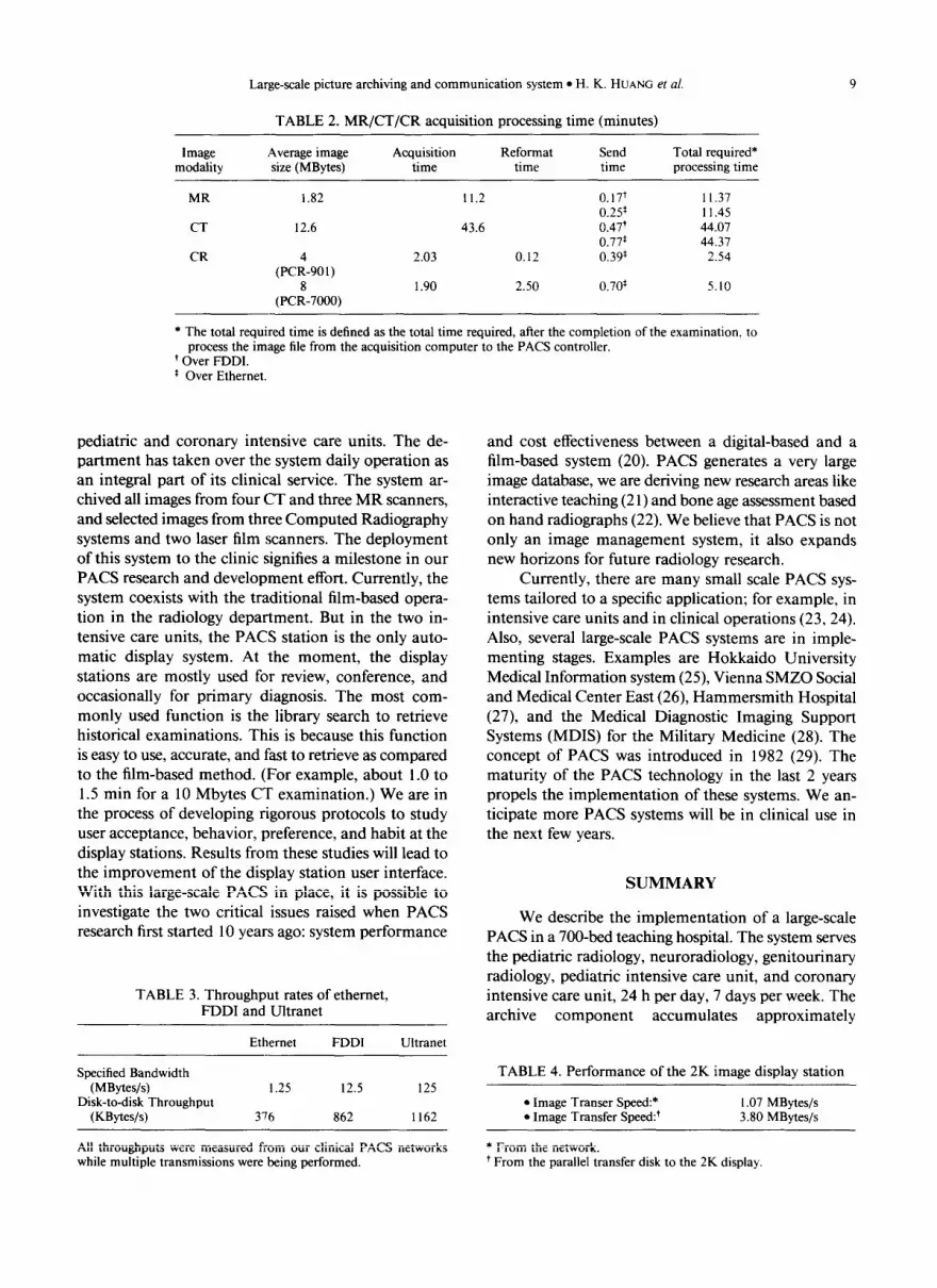
The preliminary results were obtained based on 3-month operation from late January to April 1992. We evaluated the system performance in terms of the total required processing time of an image file in all PACS components (14). After an image file is acquired from the acquisition device, it has to go through several processing steps including reformatting, rotation, and look-up table before the images can be shown on the display station. These steps require time to process at each PACS component. Table 2 shows the performance of MR, CT, and computed radiography acquisition- required processing time. Table 3 depicts the through- put rates of the communication networks including the Ethernet, FDDI (fiber distributed data interface) and UltraNet (Ultra Network Technologies, San Jose, CA). Table 4 gives the required processing time in the display component. Table 5 shows the archival com- ponent performance.
DISCUSSION
We designed a large-scale PACS in the research laboratory and have successfully implemented it in clinical environment. The system has been in operation for 3 mo, with eight display stations in pediatric ra- diology, genitourinary radiology, neuroradiology, and
Large-scale picture archiving and communication system ??H. K. HUANG et al.
TABLE 2. MR/CT/CR acquisition processing time (minutes)
Image modality
Average image Acquisition size (MBytes) time
Reformat time
Send time
Total required* processing time
MR 1.82 11.2 0.17+ II.37 0.2s I 1.45
CT 12.6 43.6 0.47’ 44.07 0.77’ 44.37
CR (PC:-90,) 2.03 0.12 0.39* 2.54
(PC:-7000) 1.90 2.50 0.70’ 5.10
* The total required time is defined as the total time required, after the completion of the examination, to process the image file from the acquisition computer to the PACS controller.
+ Over FDDI. * Over Ethernet.
pediatric and coronary intensive care units. The de- partment has taken over the system daily operation as an integral part of its clinical service. The system ar- chived all images from four CT and three MR scanners, and selected images from three Computed Radiography systems and two laser film scanners. The deployment of this system to the clinic signifies a milestone in our PACS research and development effort. Currently, the system coexists with the traditional film-based opera- tion in the radiology department. But in the two in- tensive care units, the PACS station is the only auto- matic display system. At the moment, the display stations are mostly used for review, conference, and occasionally for primary diagnosis. The most com- monly used function is the library search to retrieve historical examinations. This is because this function is easy to use, accurate, and fast to retrieve as compared to the film-based method. (For example, about 1.0 to 1.5 min for a 10 Mbytes CT examination.) We are in the process of developing rigorous protocols to study user acceptance, behavior, preference, and habit at the display stations. Results from these studies will lead to the improvement of the display station user interface. With this large-scale PACS in place, it is possible to investigate the two critical issues raised when PACS research first started 10 years ago: system performance
TABLE 3. Throughput rates of ethernet, FDDI and Ultranet
Ethernet FDDI Ultranet
Specified Bandwidth (MBytes/s)
Disk-to-disk Throughput (KBytes/s)
I .25 12.5 125
376 862 1162
All throughputs were measured from our clinical PACS networks while multiple transmissions were being performed.
and cost effectiveness between a digital-based and a film-based system (20). PACS generates a very large image database, we are deriving new research areas like interactive teaching (2 1) and bone age assessment based on hand radiographs (22). We believe that PACS is not only an image management system, it also expands new horizons for future radiology research.
Currently, there are many small scale PACS sys- tems tailored to a specific application; for example, in intensive care units and in clinical operations (23,24). Also, several large-scale PACS systems are in imple- menting stages. Examples are Hokkaido University Medical Information system (25), Vienna SMZO Social and Medical Center East (26), Hammersmith Hospital (27), and the Medical Diagnostic Imaging Support Systems (MDIS) for the Military Medicine (28). The concept of PACS was introduced in 1982 (29). The maturity of the PACS technology in the last 2 years propels the implementation of these systems. We an- ticipate more PACS systems will be in clinical use in the next few years.
SUMMARY
We describe the implementation of a large-scale PACS in a 700&d teaching hospital. The system serves the pediatric radiology, neuroradiology, genitourinary radiology, pediatric intensive care unit, and coronary intensive care unit, 24 h per day, 7 days per week. The archive component accumulates approximately
TABLE 4. Performance of the 2K image display station - ??Image Transer Speed:* I .07 MBytes/s ??Image Transfer Speed:’ 3.80 MBytes/s
* From the network. ’ From the parallel transfer disk to the 2K display.
10 Computerized Medical Imaging and Graphics
TABLE 5. Performance of the archival component (based on 7.2 MBytes imaging file size)
Required processing time for archiving* 102 s Required processing time for distributing’ 38 s Required processing time for retrieving* 88 s
* From an acquisition computer to the optical disk library (OD). ’ From an acquisition computer to a display station. * From a display station requesting the image file from the OD to the complete transmission of the file to the display station.
2 Gbytes of imaging data per working day, representing 40% of the workloads in the radiology department. The system has been integrated as an essential component in the health care delivery system in the hospital.
Acknowledgments--The authors thank the contribution from many colleagues who have associated with us in the past and present in this project, and the supports from: PHS grant number PO1 CA 5 1198, NC1 DHHS, ROl CA 39063, NC1 DHHS, ROl CA 40456, NC1 DHHS, T32 CA 09092, NCI, DHHS; Konica Corporation, Philips Medical Systems, Inc., General Electric Medical Systems, Eastman Kodak, Hitachi-Maxell, Ltd., National Center for Health Statistics, Department of Radiological Sciences Research and De- velopment funds.
REFERENCES
1.
2.
3.
4.
5.
6.
7.
8.
9.
10.
11.
12.
Huang, H.K.; Mankovich, N.J.; Wilson, G.H.; Barbaric, Z. De- velopment of a dedicated image processing laboratory for the radiology department. Noninvas. Med. Imag. 1:227-232; 1984. Huang, H.K.; Bassett, L.W.; Mankovich, N.J.; Cho, P.S.; Kan- garloo, H.; Seeger, L. Instruction in image processing for residents in diagnostic radiology. AJR 149:435-437; 1987. Taira, R.K.; Mankovich, N.J.; Boechat, M.I.; Kangarloo, H.; Huang, H.K. Design and implementation of picture archiving and communication system for pediatric radiology. AJR 150: 1117-1121; 1988. Cho, P.S.; Huang, H.K.; Tillisch, J.; Kangarloo, H. Clinical eval- uation of a radiologic picture archiving and communication sys- tem for a coronary care unit. AJR 151:823-827; 1988. Lou, S.L.; Huang, H.K. Assessment of neuroradiology picture archiving and communication system in clinical practice. AJR 159:1321-1327; 1992. Huang, H.K.; Kangarloo, H.; Cho, P.S.; Taira, R.K.; Ho, B.K.T.; Chan, K.K. Planning a totally digital radiology department. AJR 154:635-639; 1990. Huang, H.K.; Taira, R.K. Infrastructure design of a picture ar- chiving and communication system. AJR 158:743-749; 1992. Wong, A.W.K.; Taira, R.K.; Huang, H.K. Digital archive center: Implementation for a radiology department. AJR 159:1101- 1105; 1992. Stewart, B.K.; Lou, S.L.; Wong, W.K.; Huang, H.K. An ultrafast network for communication of radiologic images. AJR 156:835- 839; 1991. Weinberg, W.S.; Loloyan, M.; Chan, K.K. On-line acquisition of CT and MRI studies from multiple scanners. Proc. SPIE 1446: 430-435; 199 I. Ho, B.K.T. Automatic acquisition interfaces for computed ra- diography, CT, MR, US, and laser scanner. Comp. Med. Imag. Graph. 15:135-145: 1991. Hua& H.K.; Tecotzky, T.H.; Bazzill, T. A fiber-optic broadband CT/MR video communication system. J. Digital Imaging 5:22- 25; 1992.
January-February/ 1993, Volume 17, Number I
13. Razavi, M.; Sayre, J.W.; Taira, R.K.; Simons, M.; Huang, H.K., et al. A ROC study of pediatric chest radiographs comparing digital hardcopy film and 2K X 2K softcopy images. AJR 158: 443-448: 1992.
14. Wong, W.K.; Loloyan, M.; Lou, S.L.; Huang, H.K. On-line per- formance characteristics of a radiolow PACS. Proc. SPIE 1654:
viewing station for low cost and high performance. Proc. SPIE 1234:4 18-422: 1990.
16. ACR-NEMA Digital Imaging and Communication Standards Committee. Digital imaging and communications ACR-NEMA 300- 1988. Washington, DC: National Electrical Manufacturers Association; 1998.
17. Lewkovicz, J. The complete MUMPS. New York: Prentice Hall; 1989.
18. Breant. C.M.; Taira, R.K.; Tashima, G.H.; Huang, H.K. Issues and solutions for interfacing a PACS data base with a RIS. Proc. SPIE 1654:255-264; 1992.
19. Eldredge. S.L.; Tagawa, J.; Tecotzky, R.H.; Bazzill, T. Operation of a clinical PACS. Proc. SPIE 1654:349-354; 1992.
20.
21.
22.
23.
24.
25.
26.
27.
28.
29.
Kundel, H.L.; Seshandri, S.B.; Arenson, R.L. Clinical evaluation of PACS: Modeling diagnostic value. Proc. SPIE 1234:2 14-2 17; 1990. Sinha, S.: Sinha, U.; Kangarloo, H.; Huang, H.K. A PACS-based interactive teaching module for radiological sciences. AJR 159: 199-205: 1992. Pietka, E.; McNitt-Gray, M.F.; Kuo, M.L.: Huang, H.K. Com- puter-assisted phalangeal analysis in skeletal age assessment. IEEE-Trans. Med. Imaging 30:6 16-620; 199 1. Arenson. R.L.; Seshadri, S.; Kundel, H.L.. et al. Clinical eval- uation of a medical image management system for chest images. AJR 150:55-59; 1988. Boehme, J.M.: Chimiak, W.J.; Choplin, R.H.; Maynard, CD. Operational infrastructure for a clinical PACS. Proc. SPIE 1446: 312-317; 1991. Irie, G. Clinical experience-16 months of Hu-PACS in picture archiving and communication systems (PACS). NATO AS1 Series F, vol 74. Berlin: Springer-Verlag; 1991: 183-188. Masser, H.; Mandl, A.; Urban, M., et al. The Vienna project SMZO in picture archiving and communication systems (PACS). NATO AS1 Series F, vol. 74. Berlin: Springer-Verlag; 199 1:247- 250. Glass, H.I.; Slark, N.A. PACS and related research in the United Kingdom in picture archiving and communication systems (PACS). NATO AS1 Series F, vol. 74. Berlin: Springer-Verlag; 1991:319-324. Georinger, F. Medical diagnostic imaging support systems for military medicine in picture archiving and communication sys- tems (PACS). NATO AS1 Series F, vol. 74. Berlin: Springer- Verlag; 1991:213-230. Duerinckx, A., ed. Picture archiving and communication systems (PACS) for medical applications. Proc. SPIE 3 18:1982.
About the Author-H. K. HUANC is Professor and Vice Chairman, Director of Radiological Informatics Laboratory, Department of Ra- diology, University of California, San Francisco campus. Dr. Huang spent 10 years at UCLA, designed and implemented the PACS system there which is now in daily clinical operation. He transferred to UCSF in October, 1992. At UCSF he will develop the Radiological Infor- matics Laboratory (RIL). Two primary functions in the RIL are PACS and multimedia radiological database.
About the Author-SHYH-LIANG (ANDREW) Lou received his B.S. degree in Biomedical Engineering from Chung-Yuan Christian Uni- versity at Taiwan, R.O.C. in 1982 and the Ph.D. degree in Biomedical Physics from University of California at Los Angeles (UCLA) in 199 I. He was a Postdoctoral Scholar and Visiting Assistant Professor in the Division of Medical Imaging, Department of Radiological Sci-
Large-scale picture archiving and communication system ??H. K. HUANG et al. 11
ences at UCLA from 199 I to 1992. He is currently an Assistant Adjunct Professor in the Radiological Informatics Laboratory, De- partment of Radiology, University of California at San Francisco (UCSF). His major research activities in past 4 years have been in design and implementation of Picture Archiving and Communication Systems (PACS), digital communication methodology applied in PACS, image data compression, and computed tomography recon- struction techniques. Dr. Lou is a junior member of the American Association of Physicists in Medicine (AAPM).
About the Author-ALBERT WONG received the BS degree from Na- tional Taiwan University, Taipei, Taiwan, Republic of China, in 1965. He is a systems engineer for the Radiological Informatics Laboratory in the Radiology Department at UCSF. He is presently involved in the image acquisition, image archiving, and communication networks of the UCSF Picture Archiving and Communication System (PACS) project. Before joining the Radiological Informatics Laboratory at UCSF in 1992, he worked as a systems engineer with the Medical Imaging Division of the Department of Radiological Sciences, UCLA. Since 1986 he had been one of the major developers of the UCLA PACS. His previous work at UCLA included implementing and managing the CT/MR image acquisition, multiple communication networks, and image archiving. He is a member of the Institute of Electrical and Electronics Engineers (IEEE). His current research in- terests include systems integration, image acquisition, optical ar- chiving, and communication networks.
About the Author-KATHERINE P. ANDRIOLE received a B.S.E. de- gree in 1980, Magna Cum Laude with Departmental Distinction in Biomedical Engineering from Duke University where she was an Angier B. Duke Scholar. She received the Ph.D. degree in Electrical Engineering from Yale University in 1990 as a member of the Medical
Scientist Training Program. Dr. Andriole was a Postdoctoral Scholar in the Department of Radiological Sciences, Division of Medical Imaging at the University of California at Los Angeles School of Medicine from 199 I - 1992 and is currently a Fellow at the University of California at San Francisco School of Medicine, Department of Radiology, Radiological Informatics Laboratory. She has received a National Science Foundation Postdoctoral Research Associateship for 199 I - 1993 from the Division of Advanced Scientific Computing. Her research interests include medical image processing and analysis, picture archiving and communication systems (PACS), computed radiography (CR), and parallel processing. Dr. Andriole is a member of the Phi Eta Sigma, Tau Bata Pi, and Sigma Xi Honor Societies and a member of the Institute of Electrical and Electronics Engineers (IEEE), the Society for Photo-Optical Instrumentation Engineers (SPIE) and the American Association of Physicists in Medicine (AAPM).
About the Author-TODD M. BAZZILL received his B.S. in Electronics Engineering from Devry Institute of Technology in 1989. He was recruited from General Electric Medical Systems, where he was part of the radiological equipment specialist team, to University of Cal- ifornia at Los Angeles, Medical Imaging Division in late 1990. There, he was a member of the group that established a Picture Archiving and Communication System (PACS) for the Department of Radiol- ogy. At UCLA, Mr. Bazzih was responsible for installation and maintenance of voice, data, and video communications among mul- tiple computer facilities, including medical imaging scanners, reading rooms, and offices. In October 1992 he transferred to UCSF with Dr. H.K. Huang’s group to establish the Radiological Informatics Laboratory. At UCSF Mr. Bazzill will be designing and implementing multiple communication and video networks for image acquisition, distribution, and display of radiological images. He is a member of the Institute of Electrical and Electronics Engineers (IEEE).