Local Picture-repetition Mode Detector for Video De-interlacing
Piedad Brox, Leon Woestenberg, and Gerard de Haan, Senior Member, IEEE
Abstract— The de-interlacing of video material convertedfrom film can be perfect, provided it is possible torecognize the field-pairs that originate from the same filmimage. Various so-called film-detectors have been proposed for this purpose, mainly in the patent-literature. Typically, these detectors fail in cases where videooverlays are merged with film material, or when non-standard repetition patterns are used. Both problems occurfrequently in television broadcast. For these hybrid and/orirregular cases, we propose a detector that can detectdifferent picture-repetition patterns locally in the image.This detector combines fuzzy logic rules and spatio-temporal prediction to arrive at a highly robust decisionsignal, suitable for pixel- accurate de-interlacing ofhybrid and irregular video material. In addition to anevaluation of the performance, the paper also provides acomplexity analysis.
Index Terms— Picture-repetition Mode Detection, VideoDe- interlacing, Pull Down, Video Signal Processing,Fuzzy Inference Systems.
I. INTRODUCTION Knowledge of the picture repetition pattern is highly
relevant for several video signal processing tasks, like videocompression, picture-rate conversion and de-interlacing. Asthis information is usually not included in the transmission,the detection of picture repetition from the video data isnecessary. We shall focus on the de-interlacing application [1], which is particularly relevant, since if the field-pairs that are originated from the same image are recognizedthen the de-interlacing of video material can be perfect.
As a large percentage, often the majority, of broadcastvideo material has been converted from film, methods torealize film- mode detection are currently in demand. In thisconversion picture repetition is required, since videosignals originating from a video camera provide a picturerate of 50 Hz, or 60 Hz, whereas if the material wasregistered with a cine-camera the picture rate is only 24images per second. In order to adapt film to both standardtransmissions, a process called ’pull-down’ is performed.Basically, it consists of repeatedly scanning a film image untilit is time to show the next. For 25 Hz film shown in a 50 Hz
P. Brox is with the Instituto de Microelectronica de Sevilla (CNM-CSIC) andthe University of Seville, Spain (e-mail:[email protected]). L.M.P. Woestenberg iswith the Axon Digital Desing, Udenhout, the Netherlands (e-mail:[email protected]). G. de Haan is with the Philips Research Eindhoven,Eindhoven, the Netherlands. He is also professor at the Information andCommunication Group, Technology University of Eindhoven, the Netherlands (e-mail:[email protected]).
broadcast, every image is shown twice and the conversion is referred to as 2:2 pull-down. For 24 Hz film shown on a 60 Hz television, film images are shown alternatingly 2and 3 times, which is the so-called 3:2 pull-down process. Independent of the type of camera and repetition pattern,interlaced video signals transmit only the odd lines of oddimages and the even lines of even images.
Different detectors have been proposed to identify the field-pairs originating from the same film image to enable perfectde-interlacing, or proper picture-rate conversion. Among them zero-vector matching detectors have widely been employed by the majority of current film detectors [2]. They try tomatch the zero motion vectors on a previous field. To performit, they normally use two kinds of signals: a first todetect the frame similarity and a second one to measure the field similarity. Based on the analysis of both similarity metrics, control signals are generated. Theyindicate the mode of the video signal, i.e. video or film, andthe type and phase of the film mode, to determine the image’sposition in the 3:2 or 2:2 pull-down pattern.
Other approaches try to identify jagged edges in frames. This undesirable phenomenon appears when two fieldswith moving objects, sampled at different moments attime, are merged into a single image. Several proposals ofthis kind of detectors have been presented in the literature [3], [4].
Another detector based on edge-detection was proposed in [5]. It analyzes the position of edges in the image sinceif there is a picture repetition of the fields, edges should beat the same spatial position.
Finally, a motion vector based approach has been proposed in [6]. The sum of the length of the motion vectors isevaluated to decide if two fields are identical or not.
Recent advances in the area of film-detection can be divided into two categories. The first ones report on the increased robustness of the algorithms, whereas the second ones focus on the detection of the local video mode in hybrid video sequences.
An improved robustness is especially relevant, as an in-correct mode decision produces highly annoying artefactsin the de-interlaced video signal. The approach described in [7] reduces the number of wrong decisions due tovertical details using a new difference metric, whereas the proposed method in [8] uses a layered structure to achieve arobustness improvement.
Local detection has been motivated by the increase of TV material that combines images from different origins in a
IEEE Transactions on Consumer Electronics, Vol. 53, No. 4, NOVEMBER 2007 1648
single field. None of the techniques previously cited canlocally detect different modes in a single field, as their outputis a single flag for the entire field. They usually compare the sum of absolute values of frame and field differences over the entire field with a threshold value [2], [7]. This strategy is farfrom optimal, since the best threshold value strongly dependson the amount of motion and the level of noise in the picture. Moreover, it leaves no options to distinguish the differentmodes in a single field that occur in hybrid material. To solvethis problem, a method for detecting the film mode ofindividually moving objects within fields is described in [9].The identification of these objects is performed usingsegmentation.
Our proposal combines fuzzy logic and spatio-temporal prediction to increase the robustness of the final decision, andalso to take a decision locally on a pixel-by-pixel basis. Due tothe capacity of the fuzzy logic-based models to perform anon-linear mapping between the input and output space,they are well-known as good interpolators [10]. One exampleis the method developed in [11], which uses an adaptivede-interlacing process by weighting between ’field insertion’ and ’a spatial interpolation algorithm’. Theweighting factors are obtained analyzing, as inputs of thefuzzy system, the intra and inter-field signal differencesof the current pixel along a set of pre-determined directions.
In this paper, we propose a set of fuzzy IF-THEN rules totake a decision instead of realizing a weighted interpolation. Inthis novel approach, each rule models heuristic knowledge toidentify one of the possible picture-repetition modes on apixel-by-pixel basis. To make this pixel-accurate detectorrobust, a set of proposals are presented. Among them, the mainnovelty is the inclusion of a spatio-temporal prediction schemeinspired on recursive motion estimation [12]. Here, predictionimplies that the final decision not only corresponds to thecurrent pixel, but also the decisions in a spatio-temporal neighborhood of the current pixel are considered.
Since the decision is made on a pixel-by-pixel basis, our method can deal successfully with hybrid videomaterial. Moreover, our proposal is not limited to the recognition of the standard repetitions patterns, like the popular 2:2 or 3:2 pull-down patterns for film. This extends its applicability to any irregular, picture-repetition sequence.
This paper is organized as follows. The proposed algorithm is described in Section II. We present several proposals from a basic one to a more sophisticated one in the different subsections of Section II. The performance of the approach is proven by extensive simulations of video sequences applying the mode detection to perform different de-interlacing techniques. These results are presented in Section III. This section also includes a complexity analysis of the algorithm. Finally, we draw our conclusions in Section IV.
II. LOCAL PICTURE-REPETITION MODE DETECTOR
The proposed mode detector is a decision-makingsystem based on a set of rules. Each single rule modelsheuristic knowledge to identify locally different modes. Asmentioned in the introduction, our proposal, for de-interlacing, offers more than just the functionality of afilm-detector, as its rules deal with all possible picture-repetition patterns. To help appreciate the background of therules, we shall first briefly describe the conversionbetween film and video, which is still the most commoncause of picture-repetition in broadcast video.
The 3:2 pull-down process is common to transfer 24Hz film to 60 Hz video. To achieve this, every odd film imageis scanned twice, while every even film image is scanned threetimes as shown in Fig. 1(a). Thereafter, the signal is interlaced.
The 2:2 pull-down process is common to transfer 24Hz film to 50 Hz video. Initially, the picture-rate of thefilm is increased to 25 images per second by running thefilm 4% faster. Then, each film image is scanned twice andinterlaced, generating two video fields as shown in Fig. 1(b).
To arrive at picture-repetition detection, we calculate threedifference signals, the frame difference signal (δframe) betweenthe next and previous field at the same spatial position (x, y),and the two field differences of the current pixel: with theprevious field (δfield1) and with the next field (δfield2). In order toincrease robustness against noise the median value of eachdifference at three vertical positions is used (see Fig. 2). Theyare defined by the following expressions: δframe(x, y, n) =med (δf rame(−2) , δf rame(0) , δframe(2)) (1)
Film 24 Hz
A B
Video 60 Hz
A odd A even
A odd B even
Film 25 Hz
A B
Video50 Hz
A odd A even B odd
Line y-2
δ frame(-2)
Transmitted pixel Interpolated pixel
B odd C even
B even C odd
y
C D
C odd C even
C D
C even D odd
y+1
D odd D even
D even y+2
(a) (b) n-1 n n+1 Field
Fig. 1. Standard conversion between video and film formats: (a) 3:2Pull- down. (b) 2:2 Pull-down.
Fig. 2. Picture-repetition mode detector aperture. The shown pixels are used to calculate the local differences.
y-1
frame(0)
frame(2)
field1(-1) field2(-1)
field1(1)
field1(0)
δ
δ
δ δ
δ
δ
δ
δ field2(1)
field2(0)
P. Brox et al.: Local Picture-repetition Mode Detector for Video De-interlacing 1649
Video 60 Hz A odd A even A odd B even B odd C even C odd C even D odd D even
δfield
S
S
L
S
L
S
S
L
S
δframe
S
L
L
L
L
S
L
L
δ field1
S S L S L S S L
δ field2
S L S L S S L S
δ frame
S L L L L S L L
Video50 Hz A odd A even B odd B even C odd C even D odd D even
S
L
S
L
S
L
S
L
L
L
L
L
L
δ field1
S L S L S L S L
δ field2
L S L S L S L S
δ frame
L L L L L L L L
(a) 3:2 Pull-down (b) 2:2 Pull-down
Fig. 3. Temporal difference patterns of standard conversions.
where n denotes the field number in the sequence order:
δframe(i) (x, y, n) = |F (x, y + i, n + 1) − F (x, y + i, n − 1)| δfield1(i) (x, y, n) = |Fd (x, y + i, n) − F (x, y + i, n − 1)| δfield2(i) (x, y, n) = |Fd (x, y + i, n) − F (x, y + i, n + 1)|
To calculate the differences, a simple initial de-interlacing
algorithm is used to generate progressive frames (Fd). Typically, a vertical-temporal median or a vertical-temporal linear filter is proposed [1]. If the initial de-interlacing processwould be perfect, the difference between fields from the samesource image, as it occurs with film, should be equal to zero.With a simple and realistic initial de-interlacing algorithmalias and vertical details in the field may introduce falsedetections of motion. In order to reduce this problem, the field differences shown in expressions (2) and (3) arenormalized by vertical intra-fields differences.
The different types of temporal differences patterns areshown in Fig. 3(a) and 3(b) for the pull-down 3:2 and 2:2process, where ’L’ means a large difference and ’S’ asmall difference. Considering these temporal differencepatterns, the following knowledge can be applied to detect thedifferent modes:
1) If the frame difference is large and both field differences are large too, then the pixel corresponds to a moving object in a video sequence, where all fields are different.
2) If the frame difference is small and both field differences are also small, then the pixel corresponds to an area without motion during these two field-periods. There- fore, it must be, either a stationary area, or a moving area if the 3 fields originate from a 3 times repeated image, e.g. as it occurs with 3:2 pull-down.
3) If the frame difference is large, but one of the field differences is small while the other is large, then the current pixel belongs to a sequence with picture-repetition, where at least one field is repeated, as it occurs e.g. in 2:2 pull-down mode.
4) Otherwise, none of the modes is identified. This the may occur when the initial de-interlacing process, then necessary to calculate the field differences, suffers, from alias, because the signals are corrupted by noise, or because the image has a flat area.
This heuristic knowledge can be modelled using a system
with fuzzy IF-THEN rules, since the concepts large and small are understood as fuzzy definitions instead of threshold values.Using fuzzy logic, the concepts of ’SMALL’ and’LARGE’ are represented by fuzzy sets, the membership values of which change continuously between 0 and 1, asshown Fig. 4(a) and Fig. 4(b).
Each fuzzy IF-THEN rule in our system has antecedent1 linguistic values and a single consequent mode as shown in Table I. The minimum/maximum2
operators are selected as connectives ’and’/’or’ of theantecedents, respectively.
1 0
Membership degree of δ to LARGE
µ(δ) Membership degree of δ to SMALL
0 D0 D1 δ D2 D3 δ 1Antecedent is the common term for a condition in the fuzzy logic domain [13]
(a) (b)
Fig. 4. Membership functions for the fuzzy sets (a) LARGE, (b) SMALL.2 Minimum and maximum operators are usually defined as ’and’ and ’or’ operators in the fuzzy logic domain respectively [13]
µ(δ)
δfield δframe
1
IEEE Transactions on Consumer Electronics, Vol. 53, No. 4, NOVEMBER 2007 1650
TABLE I FU Z Z Y RU L E SE T
if antecedent then consequent1) δf rame (x,y,n) is LARGE and δf ield1 (x,y,n) is LARGE and δf ield2 (x,y,n) is LARGE MODE is video 2) δf rame (x,y,n) is SMALL and δf ield1 (x,y,n) is SMALL and δf ield2 (x,y,n) is SMALL MODE is stationary 3) (δf rame (x,y,n) is LARGE and δf ield1 (x,y,n) is SMALL and δf ield2 (x,y,n) is LARGE) or MODE is repetition
(δf rame (x,y,n) is LARGE and δf ield1 (x,y,n) is LARGE and δf ield2 (x,y,n) is SMALL) 4) otherwise MODE is undetermined
The use of the operator ’and’ forces the system toanalyze the field differences signals only if thecorresponding frame difference signal is large. This strategyincreases the robustness of the detection, since the framedifference signal is more reliable than the other differencesthat are based on imperfect initial de-interlacing results (Fd). The main advantage of the fuzzy-logic based approach is that it provides a smooth transition between one decision and another. The activation degree of a rule (αi) indicates the compatibility grade of the (ith) IF-THEN rule, which is calculated by computing the membership values of the antecedents:
α1 (x, y, n)= min(µLARGE(δframe ),µLARGE (δfield1 ),µLARGE (δfield2)) (4)
α2 (x, y, n)= min(µSMALL(δframe ),µSMALL (δfield1 ),µSMALL (δfield2)) (5)
α3 (x, y, n)= max((α3a , α3b )) (6)
α4 (x, y, n)= 1-α1 -α2 -α3 (7)where:
α3a (x, y, n)= min(µLARGE(δframe ),µLARGE (δfield1 ),µSMALL (δfield2)) (8)α3b (x, y, n)= min(µLARGE(δframe ),µSMALL (δfield1 ),µLARGE (δfield2)) (9)
For each pixel, the values α{1,2,3,4} are the output signals of the fuzzy system. Each signal corresponds to the activation degree of an individual rule and ranges from 0 to 1. Since our proposed detector aims at a pixel-by-pixel mode decision, alternative robustness measures are necessary. These are described in the following subsections.
A. Increase of the robustness of the fuzzy system decision The proposed reasoning method is based on a
single winner rule. The winner is the fuzzy IF-THEN rule that has the maximum activation degree, that is, the maximum compatibility grade with one of the patterns desvery low.
Missing line Transmitted line
3x3 Spatial-
described by the antecedents. However if multiple activationdegrees of contrary rules are activated, choosing themaximally activated mode easily results in wrong decisions.To improve this, a decision is adopted when itscorresponding rule is the most activated and also theactivation degree of the contrary rule is very low.
B. Spatio-temporal Prediction In our proposal, the final decision for the current pixel is
not only based on the decision of the system for the currentpixel, but applies ’spatio-temporal’ predictions, taking intoaccount also the decisions of the pixels in a 3x3neighborhood.
The idea is to make a decision only when one modeis actually clear, and propagate the decision until a newclear decision is taken. To reduce error propagation ameandered scanning is proposed (see Fig. 5). The detectorprocesses the even fields in a streaming fashion, that is, fromthe top-left pixel to the bottom-right pixel, whereas theodd fields are processed from the bottom-right pixel tothe top- left pixel . Four pixels in the 3x3 window are spatialneighbors and belong to the current field, and four aretemporal neighbors of the previous field as shown Fig. 5.
C. Temporal forward prediction process The temporal predictions are more complex than the spatial
prediction. To illustrate the problem, let us considerthe temporal difference pattern of pull-down 3:2 processshown in Fig. 3(a). Analysis of this pattern shows that notonly the third rule is activated but also the second one.To be exact, the second rule is activated every five fieldsof the video sequence. This means that the MODE of a pixelwith the same spatial coordinates in the previous field notalways has to agree with the current one. For any picturerepetition pattern, decisions from the previous field can betransformed into new predictions as shown in Fig. 6. Thevalues of difference signals are represented using the notation’LSL’, which means a LARGE difference of δfield1 and aSMALL difference of δfield2 and a LARGE value of δframe . Foreach value of the difference signals in the previous field, thedifferent alternatives for a pixel in the current field areshown in Fig. 6. From the knowledge of the previous mode,only the value of δfield1 can be assigned. For instance, a pixelfrom the previous field where video mode is detected impliesa large value of difference signals, that is ’LLL’. In this case,the value of δfield1 will be surely ’L’ in the next field and then,δframe will be also ’LARGE’. However, there is no informationto predict the value of δfield2. Analyzing each possibility the
Previous field (odd) Current field (even) temporal aperture
Spatial neighbours Current pixel Temporal neighbours
Fig. 5. The decisions at 9 positions in a 3x3-aperture are involved in the decision-making process.
P. Brox et al.: Local Picture-repetition Mode Detector for Video De-interlacing 1651
Previous difference values
LLL
SSS
LSL SLL
???
Updated difference values
L?L
S??
S?? L?L
???
Mode of a pixel in the previous
field MODE is video
MODE is stationary
MODE is repetition
MODE is undetermined
Temporal prediction of
the Mode MODE can be
video or repetition
MODE can be stationary or
repetition MODE can be
video, repetition and
stationary MODE is
undetermined
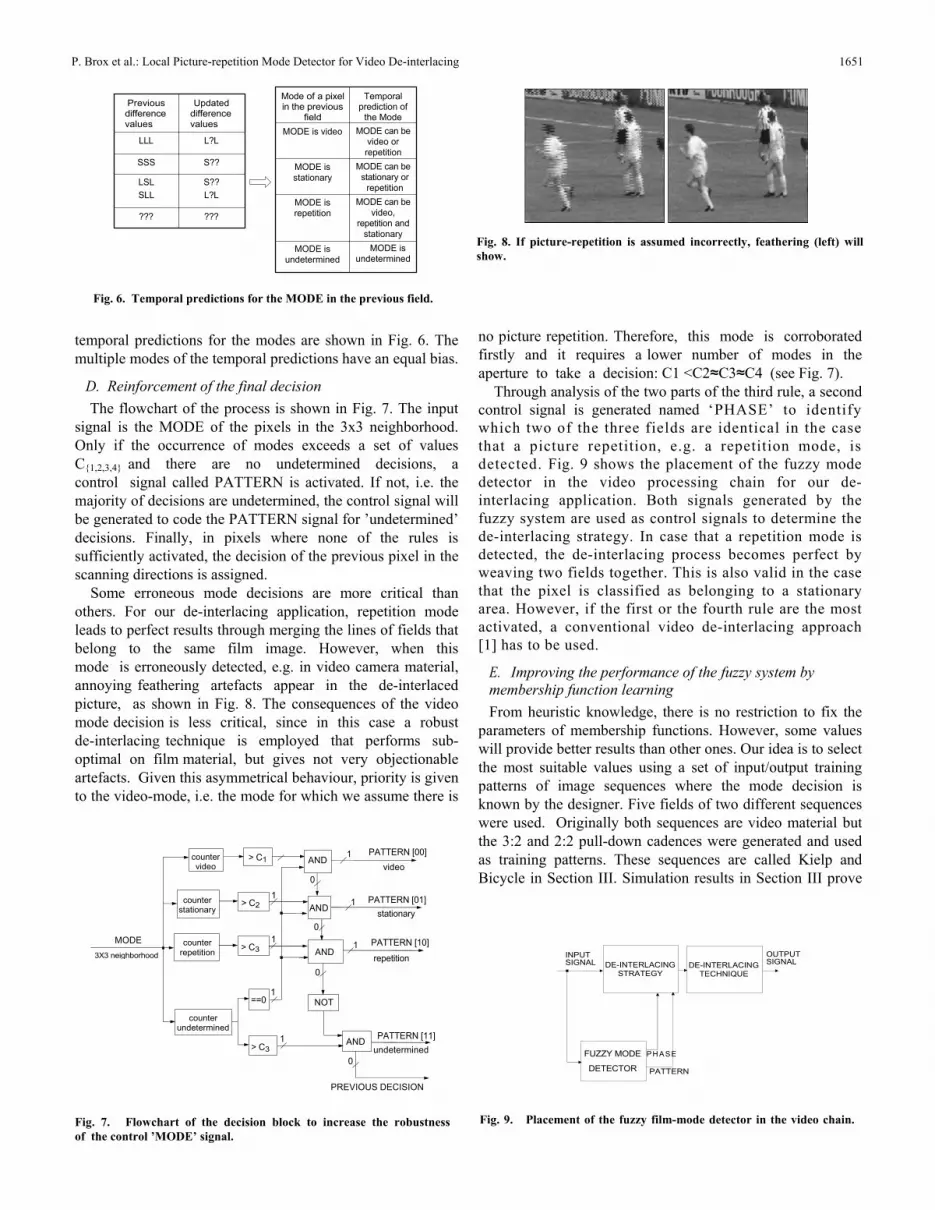
Fig. 8. If picture-repetition is assumed incorrectly, feathering (left) will show.
Fig. 6. Temporal predictions for the MODE in the previous field.
temporal predictions for the modes are shown in Fig. 6. Themultiple modes of the temporal predictions have an equal bias.
D. Reinforcement of the final decision The flowchart of the process is shown in Fig. 7. The input
signal is the MODE of the pixels in the 3x3 neighborhood.Only if the occurrence of modes exceeds a set of valuesC{1,2,3,4} and there are no undetermined decisions, acontrol signal called PATTERN is activated. If not, i.e. the majority of decisions are undetermined, the control signal willbe generated to code the PATTERN signal for ’undetermined’decisions. Finally, in pixels where none of the rules issufficiently activated, the decision of the previous pixel in thescanning directions is assigned.
Some erroneous mode decisions are more critical thanothers. For our de-interlacing application, repetition modeleads to perfect results through merging the lines of fields thatbelong to the same film image. However, when thismode is erroneously detected, e.g. in video camera material,annoying feathering artefacts appear in the de-interlaced picture, as shown in Fig. 8. The consequences of the videomode decision is less critical, since in this case a robustde-interlacing technique is employed that performs sub-optimal on film material, but gives not very objectionableartefacts. Given this asymmetrical behaviour, priority is givento the video-mode, i.e. the mode for which we assume there is
no picture repetition. Therefore, this mode is corroboratedfirstly and it requires a lower number of modes in theaperture to take a decision: C1 <C2≈C3≈C4 (see Fig. 7).
Through analysis of the two parts of the third rule, a second control signal is generated named ‘PHASE’ to identify which two of the three fields are identical in the case that a picture repetition, e.g. a repetition mode, is detected. Fig. 9 shows the placement of the fuzzy mode detector in the video processing chain for our de-interlacing application. Both signals generated by thefuzzy system are used as control signals to determine thede-interlacing strategy. In case that a repetition mode is detected, the de-interlacing process becomes perfect by weaving two fields together. This is also valid in the casethat the pixel is classified as belonging to a stationaryarea. However, if the first or the fourth rule are the most activated, a conventional video de-interlacing approach [1] has to be used.
E. Improving the performance of the fuzzy system by membership function learning From heuristic knowledge, there is no restriction to fix the
parameters of membership functions. However, some values will provide better results than other ones. Our idea is to selectthe most suitable values using a set of input/output trainingpatterns of image sequences where the mode decision isknown by the designer. Five fields of two different sequences were used. Originally both sequences are video material butthe 3:2 and 2:2 pull-down cadences were generated and usedas training patterns. These sequences are called Kielp and Bicycle in Section III. Simulation results in Section III prove that the method is robust for a wide number of test sequences.
counter video
> C1
1 PATTERN [00]video
MODE 3X3 neighborhood
counter stationary counter
repetition
> C2
> C3
1 1
AND 0
AND
0
1 1
PATTERN [01]stationary
PATTERN [10]
repetition
counter undetermined
==0 > C3
1
1
NOT
AND 0
PATTERN [11]undetermined
INPUT SIGNAL DE-INTERLACING
STRATEGY DE-INTERLACING
TECHNIQUE
FUZZY MODE PH ASE
PREVIOUS DECISION
DETECTOR PATTERN
Fig. 7. Flowchart of the decision block to increase the robustness of the control ’MODE’ signal.
Fig. 9. Placement of the fuzzy film-mode detector in the video chain.
AND 0
OUTPUT SIGNAL
IEEE Transactions on Consumer Electronics, Vol. 53, No. 4, NOVEMBER 2007 1652
TABLE II MEMBERSHIP FUNCTION PARAMETERS AFTER THE LERANING PROCESS
that the method is robust for a wide number of test sequences.For the tuning process, we used the development
environment Xfuzzy3.0 [14]. This is an environment fordesigning fuzzy sets that is composed of a set of CAD toolscovering the different stages of description, verification,simplification and synthesis of inference systems based onfuzzy logic. Xfuzzy3.0 integrates a CAD tool, named xfsl[15], to tune fuzzy systems described in the environment.
We further applied a set of training video sequences. Onlythe values D0, D1, D2 and D3 that define themembership functions have been adjusted in the learning stage. The Levenberg-Marquardt algorithm has beenselected as supervised learning algorithm and the resultsof the process are shown in Table II. This table shows thetuned parameters for each one of the modes, and also theinitial parameters of the membership functions that were fixedmanually. For the first field of the video sequence, theinitial parameters are used. For the rest of the fields, thetuned parameters for each mode is taken.
F. Mode filtering to improve robustness Since an erroneous video detection in the repetition area is
less serious than an erroneous repetition mode decision, asimple spatial filtering is performed to spread the video modedecision. Fig. 10 shows the shape of the spatial aperture. As itcan be seen, it contains more pixels in the vertical directionthan in the horizontal. The reason is that the image isprocessed
processed in a streaming direction, so mistakes are transmitted along horizontal direction. To avoid this, a higher number of pixels in vertical direction are considered. The final structural overview of the proposed detector is shown in Fig. 11.
III. PERFORMANCE OF THE PROPOSED ALGORITHM
The performance of the proposed algorithm has been evaluated in the de-interlacing application. We investigated the image quality and calculated the computational cost of the detector. Subsection A describes the cost calculations. Abrief description of the video test sequences can be found in Subsection B and finally, the overall performance is given in Subsection C.
A. Algorithm Cost
The algorithmic cost is measured using the number of floating point operations (FLOPS) as a(n inverse) figure of merit. The algorithm requires 543.7 Megas floating point operations to analyze one field of a video sequence with a resolution of 720x576. We have considered this measurement instead of computational time as it is strongly depends on the platform on which the algorithm is implemented and the efficienc of the programming
Fig. 10. 3x9-aperture for the spatial filtering. Fig. 11. Structural overview of the film detector.
FIELD MEMORY
FIELD MEMORY
δ field2
FUZZY LOGIC
SYSTEM 3x3
aperture MODE
FILTERING
δfield1Modification membership parameters
UpdatedMODE
MEMORY
δ frame
MODE
P. Brox et al.: Local Picture-repetition Mode Detector for Video De-interlacing 1653
Fig. 12. Snapshots of real sequences used to prove the performance of the proposed algorithm.
measurement instead of computational time as it stronglydepends on the platform on which the algorithm isimplemented and the efficiency of the programming.
B. Description of the Sequences
Subsection C contains results from the analysis of severalsequences. Some of them are real sequences from TVchannels or movies, and others are test video material.Forty fields of each sequence have been processed. Three ofthese sequences have been especially analyzed:
- TMF. This is an original sequence captured from a Dutchbroadcast channel called TMF. The sequence is an interlacedvideo clip (2:2 pull-down mode) with an overlaycontaining a ticker-tape video text as can be seen in Fig. 12(a). It also contains stationary areas (around the clock andthe TMF-logo).
- Fire-rose. This is an interlaced 2:2 film sequence. Thedetection of repetition mode is difficult due to the fine detailsin the man’s beard as shown in Fig. 12(b). Moreover thissequence contains a very low level of motion.
- Renata. This sequence has been used to show theimprovements introduced by the individual robustnessmeasures explained in Section II. It is originally a video scene. However, it has been artificially transformed intoan interlaced 2:2 repetition mode. The sequence has thenbeen converting into a hybrid sequence, by adding ahorizontally horizontally moving video text in the middle ofthe fields, as shown in Fig. 12(c).
C. Simulation Results To prove the performance of the proposed detector, the
three-fields VT filtering approach [16] is used if the ’video’ or’undetermined’ mode is detected. On the other hand, if one ofthe ’repetition’ mode is detected, the de-interlacing process isimplemented by weaving. Comparing the de-interlaced withthe original progressive picture of Renata, a MeanSquared Error can be calculated. Fig. 13 shows the relativeMSE-score as a percentage of the MSE-score obtained withthe VT filtering [16]. As can be seen, our final proposal
reduces the total MSE error with almost 60 %. It includes the improvements that are described in subsections {A, B, C, D,E, F} of Section II. The results achieved by the proposal witha modification of membership function parameters are slightly better (column P4 in Fig. 13) than the obtained with fixedparameters (column P3 in Fig. 13).
The detector has also been used to de-interlace the real sequences shown in Tables III and IV. It decreasesthe total MSE score by a high factor in percentage (almost 100%) in the majority of film sequences (seeTable III). This not only produces a perfectly de-interlacedimage, but also considerably reduces the complexity as weaving is the method with the lowest computational cost. Due to the presence of low motion and/or a high number of the details, repetition mode is not well detected in some of the film sequences and the MSE only falls to 40%. This is not crucial for de-interlacing applications because conventional de-interlacing is applied when actual repetition is misinterpreted as video.
Finally, the total MSE is slightly reduced when the detector is used for video sequences (see Table IV). This isdue to the improved de-interlacing of the few static areas.Although the modification of membership function parameters does not introduce many advantages for the Renata hybridTables III and IV.
sequence, it is necessary to achieve good results for somesequences in Tables III and IV.
The response of the detector was also analyzed for the TMFand Fire-rose sequences. The output modes when processingthe snapshot in Fig. 12(a) can be visually corroborated in Fig.14(a). In this figure, white color means repetition mode, lightg grey means stationary areas, dark grey corresponds to videomode and black color shows zones where the decision is notclear. As can be seen, the critical areas of the field arecorrectly detected. The MSE value for the TMF sequence could not be included in Table III since the originalprogressive material is not available.
The performance of the original Fire-rose (film material)sequence is perfect as shown in Table III. If this sequence istransformed into video by eliminating the repeated fields,
video mode is also correctly detected despite the low level of motion as shown Fig. 14(b).
Finally, a test is proposed to prove the advantages of using fuzzy definitions of the concepts SMALL and LARGE insteadof crisp definitions. The results show a more criticaldistinction among the different mode areas of the field if crispdefinitions are used. This produces serious mistakes as it canbe seen in Fig. 15(a) for Renata hybrid sequence and in Fig. 15(b) for TMF sequence.
Unfortunately, there is no competitive detector that performs a local picture repetition mode detection in currentscientific literature. This is why comparisons with otherproposals of similar characteristics are not included in this section.
IV. CONCLUSIONS The de-interlacing of video material converted from film can be perfect, provided it is detected correctly.Typically, however, available detectors fail in cases where video overlays are merged with film material, or when non-standard repetition patterns are used. Both problems occurfrequently in television broadcast. For these hybrid and/or irregular cases, we have proposed a detector that iscapable to detect locally in the image different picture-repetition patterns. By distinguishing only the following cases:
- Stationary, i.e. all 3 fields show object at same position - No identical fields, i.e. all 3 fields show object at different
position Paired identical fields case A, first two fields show object at same position, third field at different position
i i hi d fi ld diff i i
Fig. 14. Mode decisions taken by the system for (a) TMF and (b)Renata sequences. White indicates repetition, light grey stationary,dark grey video and black are unclear areas.
(a) Renata sequence (b) TMF sequence
Fig. 15. Simulation results using crisp definitions of LARGE and SMALL.
P. Brox et al.: Local Picture-repetition Mode Detector for Video De-interlacing 1655
Paired identical fields case B, last two fields show objectat same position, first field at different position - Unclear, i.e. the local data is ambiguous we designed a
picture repetition detector, suitable for all possible patternswithout limitation to the common patterns, like 2:2 and 3:2pull-down.
For instance, a long arbitrary cadence such as 3:2:2:3 canbe detected since the rules antecedents only computeabsolute differences among three consecutive fields. Thedetector combines fuzzy logic rules, to deal withuncertain cases, and uses spatio-temporal prediction to geta robust decision signal even in unclear areas. Ourevaluation shows a very favourable performance and anattractive low computational complexity.
REFERENCES
[1] G. de Haan and E. B. Bellers, De-interlacing - an overview. Proc. of theIEEE, vol. 86, Issue 9, pp. 1839-1857, Sep. 1998.
[2] T. C. Lyon and J. J. Campbell, Motion sequence pattern detector 1, 1991. United States Patent Office US 4,982,290.
[3] C. Correa and R. Schweer, Film mode detection procedure and device.Assignee: Deutsche Thomson-Brandt GMBH, Villingen-Schwennigen (DE), July 1, 1998. European Patent Office 0567072B1.
[4] H. Y. W. Lucas, Progressive/interlace and redundant field detectionfor encoder. Applicant: STMICRO-Electronics Asia Pacific PTE LTD,Singapore, June, 2000. World Intellectual Property Organization,International Publication Number: WO 00/33579.
[5] P. Swan, System and method for reconstructing noninterlacedcaptured content for display on a progressive screen. Assignee: ATETechnologies, Inc. Thornhill, anada, Apr. 25, 2000. United StatesPatent Office US 6,055,018.
[6] G. de Haan, H. Huijgen, P .Biezen, and O. Ojo, Method and apparatus fordiscriminating between movie film and non-movie film and generating apicture signal processing mode control signal. Assignee: U.S. Philips Corporation, New York, USA, Nov. 15, 1994. United StatesPatent Office US 5,365,280.
[7] A. Dommisse, Film detection for advanced scan rate converters, M.Sc.Thesis, TUE, Eindhoven, Aug. 2002.
[8] C.-C. Ku and R.-K. Liang, Robust Layered Film-Mode Source 3:2Pulldown Detection/Correction. IEEE Trans. on ConsumerElectronics, vol.50, no.4, pp. 1190-1193, Nov. 2004.
[9] G. de Haan and R. B. Wittebrood, Recognizing film and videoobject occuring in parallel in single television signals fields. Assignee:Konin- klijke Philips Electronics N. V., Eindhoven, NL, Aug. 30,2005. United States Patent Office US 6,937,655.
[10] J. L. Castro, Fuzzy logic controllers are universal approximators. IEEETrans. on ystems, Man and Cybernetics, vol.25, no.4, pp. 629-635, Apr. 1995.
[11] L. He and H. Zhang, Motion object video on film detection and adaptivede-interlace method based on fuzzy logic. Assignee: nDSP Corporation,Campbell, CA, Sep. 28, 2004. United States Patent Office US 6,799,168.
[12] G. de Haan, and P. W. A. C. Biezen, Sub-pixel motion estimation with 3-D recursive search block-matching.Signal Processing: Image Commu-nication 6, pp.229-239, June 1994.
[13] E. Cox, The Fuzzy Systems Handbook: A Practitioner’s Guide to Build-ing, Using, and Maintaining Fuzzy Systems. AP Professional Editorial (2nd edition).
[14] F.J. Moreno-Velo, I. Baturone, S. Sánchez-Solano, and A. Barriga,Rapid design of complex fuzzy systems with Xfuzzy.Proc. IEEE Int. Conf. on Fuzzy Systems, pp.342-347, St. Louis, USA, May 2003.
[15] F.J. Moreno-Velo, I. Baturone, R. Senhadji, and S. Sánchez-Solano, Tuning complex fuzzy systems by supervised learningalgorithms.Proc. IEEE Int. Conf. on Fuzzy Systems, pp.226-231, St. Louis, USA, May 2003.
[16] M. Weston, Interpolating lines of video signals. Assignee: BritishBroadcasting Corporation, London, GB2, Dec. 6, 1988. UnitedStates Patent Office US 4,789,893.
Piedad Brox was born in 1979 in Córdoba, Spain. She received the degree in Electronic Physics from the University of Córdoba in 2002, and the Advanced Studies Degree in Microelectronics fromthe University of Seville in 2004.
Since 2002, she has been with the Microelectronics Institute of Seville (IMSE), which belongs to the Spanish Research Council (CSIC) and the University of Seville. She received a fellowship of Introduction to Research for Undergraduate Students during 2002.
Currently, she is a Postgraduate Re- search Fellow and has a PostgraduateFellowship under F.P.U. program from the Spanish government. Herresearch areas are fuzzy image processing algorithms and their hardware implementation (starting from high-level descriptions to prototyping inFPGAs). She belongs to the ’Digital and Mixed Signal Integrated CircuitDesign Group’ of IMSE.
Leon Woestenberg received the M.Sc. degree in Electrical Engineering from the University of Tech- nology Eindhoven in 2006. His final project involved content-adaptive video de-interlacing under supervision of Gerard de Haan.
Since 2000 he has been employed, and performed his M.Sc. final project at Axon Digital Design, a manufacturer of audio and video processing systems for television broadcast and production. As an embedded software engineer he developed and re-used open-source software in a commercialenvironment.
Since 1992 he is involved in open-source software projects as developerand project manager. Currently, since 2004, as a senior systems designer hedesigns signal processing and control systems and software and acquires andprepares newly available technology for use in future designs.
His professional interests involve operating systems, hardware/software codesign, video and graphics, the open-source development model and the useof open-source software in commercial environments.
Gerard de Haan (Senior Member, IEEE) received B.Sc., M.Sc., and Ph.D. degrees from Delft Uni-versity of Technology in 1977, 1979 and 1992 respectively. He joined Philips Research in 1979. He has led research projects in the area of video processing, and participated in European projects. He has coached students from various universities, and teaches since 1988 for the Philips Centre for Technical Training. Currently, he is a Research Fellow in the Video Processing & Visual Perception group of Philips Research Eindhoven, and a part-time full Professor at the Eind-
hoven University of Technology teaching ”Video Processing for Multimedia Systems”.
He has a particular interest in algorithms for motion estimation, video rate conversion, and image enhancement. His work in these areas hasresulted in several books, more than 120 papers, about 100 patents, andvarious commercially available ICs. He was the first place winner in the1995 and 2002 ICCE Outstanding Paper Awards program, the second placewinner in 1997, 1998 and 2003, and the 1998 recipient of the Gilles HolstAward. In 2002, he received the Chester Sall Award from the IEEE ConsumerElectronics Society.
The Philips ‘Natural Motion Television’ concept, based on his PhD-study received the European Video Innovation Award of the Year 95 fromthe European Imaging and Sound Association. In 2001, the successor ofthis concept ”Digital Natural Motion Television” received a ”Business Innovation Award” from the Wall Street Journal Europe. Gerad de Haan is a Senior Member of the IEEE.