Dynamic Restructuring of Recovery Nets Rachid Hamadi Boualem Benatallah School of Computer Science and Engineering The University of New South Wales Sydney NSW 2052, Australia {rhamadi,boualem}@cse.unsw.edu.au Abstract A Self-Adaptive Recovery Net (SARN) is an extended Petri net model for specifying exceptional behavior in workflow sys- tems. SARN caters for high-level recovery policies that are incorporated either with a single task or a set of tasks, called a recovery region. A recovery region delimits the part of the workflow from which the associated recovery policies take place. In this paper, we assume that SARN is initially partitioned into recovery regions by workflow designers who have a priori ex- pectations for how exceptions will be handled. We propose a pattern-based approach to dynamically restructure SARN par- tition. The objective is to continuously restructure recovery regions within SARN partition to reflect the dynamic changes in handling exceptions. The restructuring of SARN partition is based on the observation of predefined recovery patterns. Keywords: Self-Adaptive Recovery Net (SARN), workflow systems, recovery region, predefined recovery patterns, region restructuring operations. 1 Introduction A workflow management system (WfMS) provides a central control point for defining business processes and orchestrating their execution (Georgakopoulos, Hornick & Sheth 1995). A major limitation of current WfMSs is their lack of support for dynamic adapta- tions (Casati, Ceri, Pernici & Pozzi 1998). Support- ing the handling of exceptions is of great importance in areas such as clinical environment, office automa- tion, flexible manufacturing systems, and design of production lines. In our previous work, we introduced Self-Adaptive Recovery Net (SARN), an extended Petri net model, for specifying exceptional behavior in workflow sys- tems (Hamadi & Benatallah 2004). This model adapts the structure of the underlying Petri net at run time to handle exceptions while keeping the Petri net design simple. It caters for high-level recovery policies that are incorporated either with a single task or a set of tasks called a recovery region. A recovery region delimits the part of the workflow from which the associated recovery policies take place. Recovery policies are generic directives that model exceptions at design time together with a set of primitive oper- ations used at run time to handle the occurrence of exceptions. In this paper, we assume that SARN is initially partitioned into recovery regions by workflow design- ers who have a priori expectations for how exceptions Copyright c 2005, Australian Computer Society, Inc. This pa- per appeared at the 16th Australasian Database Conference (ADC2005), University of Newcastle, Newcastle, Australia. Conferences in Research and Practice in Information Technol- ogy, Vol. 39. H.E. Williams and G. Dobbie, Eds. Reproduction for academic, not-for profit purposes permitted provided this text is included. will be handled. We propose a pattern-based ap- proach to dynamically restructure SARN partition. The objective is to continuously restructure recovery regions within SARN partition by being responsive to the ways past exceptions have been handled. The restructuring of SARN partition is based on the ob- servation of predefined recovery patterns. Our con- tribution is twofold: • Predefined recovery patterns. These patterns rep- resent pre-identified sequences of recovery proce- dures. They are used as heuristics for SARN partition restructuring. The discovery of fre- quent patterns helps workflow administrators de- cide what kind of restructuring would be desir- able to improve SARN partitioning. Transforma- tions of SARN partition over time result in offer- ing improved alternative of its structure based on the observation of recovery patterns. • Region restructuring operations. We propose two groups of region restructuring operations, namely split operations and merge operations. They are used to dynamically transform the structure of SARN partition. Region restructuring should only be allowed in a valid way. The system must guarantee the correct- ness of the modified SARN partition w.r.t. consis- tency constraints (such as reachability and absence of deadlock), so that constraints that were valid be- fore the dynamic modification of SARN are also valid after it. The rest of the paper is organized as follows. Sec- tion 2 describes the partitioning of the SARN model into recovery regions along with a motivating exam- ple. Section 3 introduces the predefined recovery pat- terns. Their corresponding region restructuring oper- ations are discussed in Section 4. Section 5 describes the HiWorD (HIerarchical WORkflow Designer) pro- totype. Finally, Section 6 reviews some related work and concludes the paper. 2 SARN Partitioning In this section, we first recall the definition of Self- Adaptive Recovery Net (SARN). Then, we introduce the notions of recovery region and SARN partition. Finally, we illustrate these concepts by an example. 2.1 SARN Definition SARN extends Petri nets (Murata 1989, Peterson 1981) to model exception handling through recovery transitions and recovery tokens. In SARN, there are two types of transitions: standard transitions repre- senting workflow tasks to be performed and recovery transitions that are associated with workflow tasks to
Transcript
Dynamic Restructuring of Recovery Nets
Rachid Hamadi Boualem Benatallah
School of Computer Science and EngineeringThe University of New South Wales
Sydney NSW 2052, Australia{rhamadi,boualem}@cse.unsw.edu.au
Abstract
A Self-Adaptive Recovery Net (SARN) is an extended Petrinet model for specifying exceptional behavior in workflow sys-tems. SARN caters for high-level recovery policies that areincorporated either with a single task or a set of tasks, calleda recovery region. A recovery region delimits the part of theworkflow from which the associated recovery policies take place.In this paper, we assume that SARN is initially partitioned intorecovery regions by workflow designers who have a priori ex-pectations for how exceptions will be handled. We propose apattern-based approach to dynamically restructure SARN par-tition. The objective is to continuously restructure recoveryregions within SARN partition to reflect the dynamic changesin handling exceptions. The restructuring of SARN partitionis based on the observation of predefined recovery patterns.
A workflow management system (WfMS) provides acentral control point for defining business processesand orchestrating their execution (Georgakopoulos,Hornick & Sheth 1995). A major limitation of currentWfMSs is their lack of support for dynamic adapta-tions (Casati, Ceri, Pernici & Pozzi 1998). Support-ing the handling of exceptions is of great importancein areas such as clinical environment, office automa-tion, flexible manufacturing systems, and design ofproduction lines.
In our previous work, we introduced Self-AdaptiveRecovery Net (SARN), an extended Petri net model,for specifying exceptional behavior in workflow sys-tems (Hamadi & Benatallah 2004). This modeladapts the structure of the underlying Petri net atrun time to handle exceptions while keeping the Petrinet design simple. It caters for high-level recoverypolicies that are incorporated either with a single taskor a set of tasks called a recovery region. A recoveryregion delimits the part of the workflow from whichthe associated recovery policies take place. Recoverypolicies are generic directives that model exceptionsat design time together with a set of primitive oper-ations used at run time to handle the occurrence ofexceptions.
In this paper, we assume that SARN is initiallypartitioned into recovery regions by workflow design-ers who have a priori expectations for how exceptions
will be handled. We propose a pattern-based ap-proach to dynamically restructure SARN partition.The objective is to continuously restructure recoveryregions within SARN partition by being responsiveto the ways past exceptions have been handled. Therestructuring of SARN partition is based on the ob-servation of predefined recovery patterns. Our con-tribution is twofold:
• Predefined recovery patterns. These patterns rep-resent pre-identified sequences of recovery proce-dures. They are used as heuristics for SARNpartition restructuring. The discovery of fre-quent patterns helps workflow administrators de-cide what kind of restructuring would be desir-able to improve SARN partitioning. Transforma-tions of SARN partition over time result in offer-ing improved alternative of its structure based onthe observation of recovery patterns.
• Region restructuring operations. We proposetwo groups of region restructuring operations,namely split operations and merge operations.They are used to dynamically transform thestructure of SARN partition.
Region restructuring should only be allowed in avalid way. The system must guarantee the correct-ness of the modified SARN partition w.r.t. consis-tency constraints (such as reachability and absenceof deadlock), so that constraints that were valid be-fore the dynamic modification of SARN are also validafter it.
The rest of the paper is organized as follows. Sec-tion 2 describes the partitioning of the SARN modelinto recovery regions along with a motivating exam-ple. Section 3 introduces the predefined recovery pat-terns. Their corresponding region restructuring oper-ations are discussed in Section 4. Section 5 describesthe HiWorD (HIerarchical WORkflow Designer) pro-totype. Finally, Section 6 reviews some related workand concludes the paper.
2 SARN Partitioning
In this section, we first recall the definition of Self-Adaptive Recovery Net (SARN). Then, we introducethe notions of recovery region and SARN partition.Finally, we illustrate these concepts by an example.
2.1 SARN Definition
SARN extends Petri nets (Murata 1989, Peterson1981) to model exception handling through recoverytransitions and recovery tokens. In SARN, there aretwo types of transitions: standard transitions repre-senting workflow tasks to be performed and recoverytransitions that are associated with workflow tasks to
adapt the recovery net in progress when an excep-tion event occurs. There are also two types of tokens:standard tokens for the firing of standard transitionsand recovery tokens associated with recovery policiesfor the firing of recovery transitions. There is one re-covery transition per type of task exception, that is,when a new recovery policy is designed, a new recov-ery transition is added. When an exception (such as atime out) within a task occurs, an event is raised anda recovery transition will be enabled and fired. Thecorresponding sequence of basic operations (such ascreating a place and deleting an arc) associated withthe recovery transition is then executed to adapt thestructure of SARN that will handle the exception.
In the following, we recall the formal definition ofSARN (Hamadi & Benatallah 2004).
Definition 2.1 (SARN)A Self-Adaptive Recovery Net (SARN) is a tupleRN = (P, T, T r, F, i, o, `, M) where:
• P is a finite set of places representing the statesof the workflow,
• T is a finite set of standard transitions (P ∩T =∅) representing the tasks of the workflow,
• Tr is a finite set of recovery transitions (T∩Tr =∅ and P ∩ Tr = ∅) associated with workflowtasks to adapt the net in-progress when an excep-tion event occurs. There is one recovery transi-tion per type of task exception,
• F ⊆ (P × (T ∪ Tr)) ∪ ((T ∪ Tr) × P ) is a set ofdirected arcs (representing the control flow),
• i is the input place of the workflow with •i = ∅,
• o is the output place of the workflow with o• = ∅,
• ` : T → A ∪ {τ} is a labeling function where Ais a set of task names. τ denotes a silent (or anempty) task (represented as a black rectangle),and
• M : P → N × N represents the mapping fromthe set of places to the set of integer pairs wherethe first value is the number of standard tokens(represented as black small circles within places)and the second value the number of recovery to-kens (represented as black small rectangles withinplaces). 2
Recall that for x ∈ P∪T , the pre-set of x is definedas •x = {y ∈ P ∪ T / (y, x) ∈ W} and the post-set ofx is defined as x• = {y ∈ P ∪ T / (x, y) ∈ W}.
In the SARN model, there are some primitive op-erations that can modify the net structure such asadding an arc and disabling a transition (see (Hamadi& Benatallah 2004)). Several of these basic opera-tions are combined in a specific order to handle dif-ferent exception events. The approach adopted is touse one recovery transition to represent one type ofexception. Thus, a recovery transition represents acombination of several basic operations. When anexception occurs, a recovery token is injected into aplace and the set of primitive operations associatedwith the recovery policy are triggered.
2.2 Recovery Region
A recovery region is a connected set of places andtransitions. A recovery region has one input placeand one output place. The output place of a recoveryregion is typically an input place for the eventual nextrecovery region(s). To avoid an overlapping of recov-ery regions, we will separate them so that between
the output place of a recovery region and the inputplace of the eventual subsequent recovery region(s), asilent transition transfers the token from the recoveryregion to the subsequent recovery region(s).
A recovery region is then a subworkflow that canbe seen as a unit of work from the business perspec-tive and to which a set of region-based recovery poli-cies may be assigned. A default region-based recoverypolicy CompensateRegion can be associated with anyrecovery region. CompensateRegion removes the ef-fects of all already executed tasks of the completedor running recovery region. For more details aboutregion-based recovery policies see Table 1 and referto (Hamadi & Benatallah 2004). As such, a recoveryregion is more than a traditional subworkflow. For-mally, a recovery region is defined as follows.
Definition 2.2 (Recovery Region)Let RN = (P, T, T r, F, i, o, `, M) be a SARNnet. A recovery region is a subnet R =〈PR, TR, T rR, FR, iR, oR, `R, SR〉 of RN where:
• PR ⊆ P is the set of places of the recovery region,
• TR ⊆ T denotes the set of transitions of the re-covery region R,
• TrR ⊆ Tr denotes the set of task recovery tran-sitions of R,
• FR ⊆ F represents the control flow of R,
• iR ∈ PR is the input place of R,
• oR ∈ PR is the output place of R,
• `R : TR → A∪ {τ} is a labeling function,
• SR is a finite set of region recovery transitionsassociated with the recovery region R to adaptthe net in-progress when a region exception eventoccurs. There is one recovery transition per typeof region exception, and
• Let TR = {t ∈ T | t•∩PR 6= ∅ ∧ •t∩PR 6= ∅}.Then R must be connected (i.e., there must notbe any isolated places or transitions). 2
R represents the underlying Petri net of the recov-ery region that is restricted to the set of places PR
and the set of transitions TR.
2.3 SARN Partition
For a specific SARN net, there can be several differ-ent ways to divide it into recovery regions. A SARNpartition is a division of the set of places into pairwisedisjoint recovery regions. Formally, a SARN partitionis defined as follows.
Definition 2.3 (SARN Partition)Let RN = (P, T, T r, F, i, o, `, M) be a SARN net. ASARN partition Π = {Rk | k = 1, .., n} of the set P ofplaces is a decomposition into non-empty and disjointrecovery regions Rk, k = 1, ..n, that is:
• ∀ k = 1, .., n Rk 6= ∅,
• ∀ k = 1, .., n Rk contains one input place,
• ∀ k = 1, .., n Rk contains one output place,
•⋃n
k=1 Rk = P ,
• ∀ k, j ∈ {1, .., n}, k 6= j Rk ∩ Rj = ∅,
• For each Rk, let Tk = {t ∈ T | t• ∩ Rk 6= ∅ ∧•t ∩ Rk 6= ∅}. Then ∀ k, j ∈ {1, .., n}, k 6=j Tk ∩ Tj = ∅. 2
The set Tk denotes the set of transitions of the re-covery region Rk. The last condition means that thereare no shared transitions between recovery regions.
Table 1: Region-Based Recovery Policies
Recovery Policy Notation Region Status Brief Description
SkipRegion(Event e, Region R) SReR Running Skips the running task(s)
of the region R to theimmediate next task(s) ofit if the event e occurs
SkipRegionTo(Event e, Region R, TaskSet T ) SRT eR,T Running Skips the running region
R to the specificnext task(s) T ifthe event e occurs
CompensateRegion(Event e, Region R) CReR Completed Removes the effect of all
or already executed tasks ofRunning the completed or running
region R if the evente occurs
CompensateRegionAfter(Event e, Region R) CRAeR Completed Removes the effect of an
already executed region Rjust after completing itif the event e occurs
RedoRegion(Event e, Region R) RReR Completed Repeats the execution of
or all already completedRunning tasks of the completed
or running region Rif the event e occurs
RedoRegionAfter(Event e, Region R) RRAeR Completed Repeats the execution of
an already completedregion R just after it endsif the event e occurs
AlternativeRegion(Event e, Region R, Region R’) ARe
R,R′ Running Allows an alternative
execution of a region R
by another region R’if the event e occurs
TimeoutRegion(Region R, Time d) TRdR Running Fails a region R if not
completed within atime limit d. Theexecution is frozen
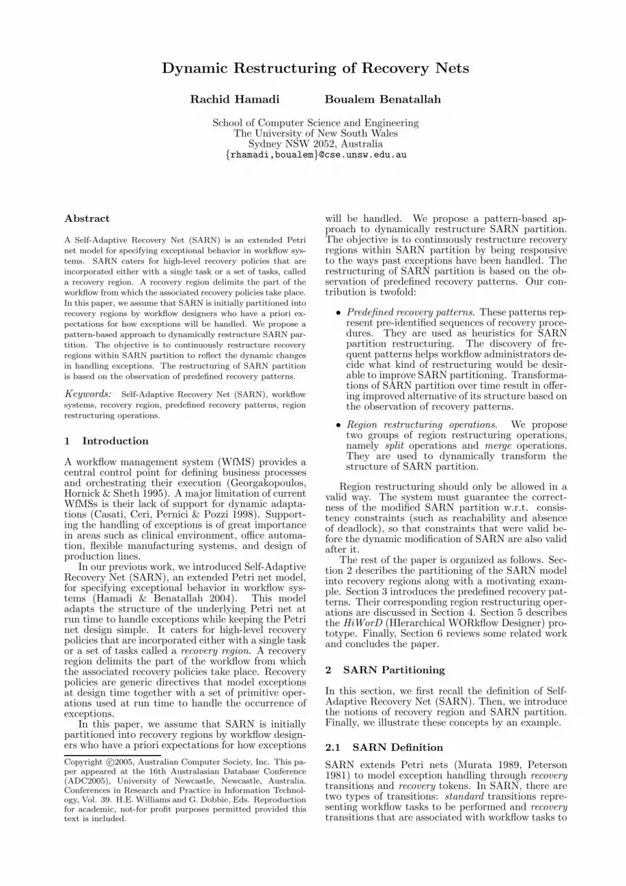
2.4 A Motivating Example
We give here an example of a workflow representingordering flight tickets over the Internet to illustratethe concept of a recovery region (see Figure 1).
i
R2
R3
R5
o R6
o3
i3
R4
R1
Get TripOrder
Plan Trip
Submit TripOrder
ReserveSeats
Get TicketsOrder
Select Legs
OrderTickets
ChargeCredit Card
ConfirmFlights
GetConfirmation
ReceiveeTickets
GenerateItinerary
Issue eTickets
PrepareTrip
IssueItinerary
ReceiveItinerary
Figure 1: The Ordering Flight Tickets Workflow as aSARN Partition
A customer plans her trip by specifying the vari-ous stages of the overall journey (the Plan Trip task).She sends this information together with the list ofall participants of the trip and the information aboutthe credit card to be charged for the ordered tick-ets to the travel agent (the Submit Trip Order task).She then waits for the submission of the electronic
tickets (the Receive eTickets task) as well as the fi-nal itinerary for the trip (the Receive Itinerary task)before preparing for the trip by making other arrange-ments such as hotel booking and car rental (the Pre-pare Trip task). When the travel agent receives thecustomer’s trip order (the Get Trip Order task), hewill determine the legs for each of the stages (the Se-lect Legs task) and submits these legs together withthe information about the credit card to be chargedto the airline company (the Order Tickets task). Theagent then waits for the confirmation of the flights(the Get Confirmation task), which includes the ac-tual seats reserved for each participant. This infor-mation is completed into an itinerary (the GenerateItinerary task) and sent to the customer (the IssueItinerary task). When the airline receives the ticketsorder submitted by the agent (the Get Tickets Or-der task), the requested seats will be checked and, ifavailable, assigned to the corresponding participants(the Reserve Seats task). After that, the credit cardwill be charged (the Charge Credit Card task), andthe updated leg information sent back to the agent asconfirmation of the flights (the Confirm Flight task).Finally, once the travel agent receives confirmation,the airline sends the electronic tickets by e-mail tothe customer (the Issue eTickets task).
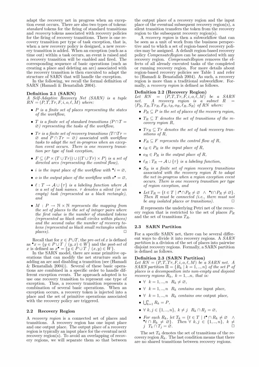
We use our HiWorD (HIerarchical WORkflowDesigner) tool to model workflows (Benatallah,Chrzastowski-Wachtel, Hamadi, O’Dell & Susanto2003). For the Ordering Flight Tickets workflow ex-ample (see Figure 1), starting from a single place andusing a succession of place and transition refinementrules (Chrzastowski-Wachtel, Benatallah, Hamadi,O’Dell & Susanto 2003), the abstract workflow shownin Figure 2 is obtained. Places represent recovery re-gions and black rectangles stand for silent (or empty)transitions. Silent activities, called dummy activi-ties in (WfMC 1999), have no associated work or re-
sources.By further refining regions (i.e., places) R1 through
R6, we obtain the flat workflow represented in Fig-ure 1 as a SARN partition where recovery regions aresurrounded by dotted lines.
Order Trip(R2)
Payment(R3)
Trip Planning(R1)
eTicket(R4)
Trip Preparation(R6)
Itineriry(R5)
Figure 2: The Ordering Flight Tickets Workflow asan Abstract SARN Partition
3 Predefined Recovery Patterns
In this section, we discuss predefined recovery pat-terns that suggest how to dynamically restructureSARN partition based on the recorded previous exe-cutions.
It is possible to split a recovery region into two re-covery sub-regions or merge two consecutive recoveryregions. An example where splitting a recovery regioninto two successive recovery sub-regions is advisableis when exception events and activities involved intheir recovery always occur in one specific part of therecovery region. This avoids undoing and redoing alarge and expensive amount of work, and the possi-bility of cascaded compensations. Another examplewhere merging two consecutive recovery regions intoone recovery region is suitable is when RedoRegionexception events occurring in one recovery region al-ways involve activities of the previous recovery regionfor their handling.
It should be noted that merging recovery regionsis only appropriate when frequent pre-identified se-quences of similar recovery procedures have beenobserved. Furthermore, the approach applies onlyto CompensateRegion, CompensateRegionAfter, Re-doRegion, and RedoRegionAfter recovery policies.
We first introduce some definitions and then dis-cuss the predefined recovery patterns.
3.1 Workflow Execution Log
Data mining is the task of discovering valuable in-formation in data (Berry & Linoff 2000). Our typeof data is relational databases. For our purpose, weuse the following format for the workflow log. Eachexecution of the workflow, recorded in the log file,is a sequence of events that include start time andcompletion time of each activity, the resources thatexecuted it, its input data, and its output data.
Definition 3.1 (Execution Log)The log of one execution of the workflow is a sequenceof events 〈W, I, A, Ts, Tc, AR, Din, Dout〉 where:
• W is the identifier of the workflow,
• I is the identifier of the workflow instance,
• A is the identifier of the activity,
• Ts is the start time of the activity,
• Tc is the completion time of the activity,
• AR is the set of resources used by the activity,
• Din is the set of input data of the activity, and
• Dout is the set of output data of the activity. 2
In order to use workflow log data when searchingfor recurring recovery patterns, we make some trans-formations to the workflow log file. First, we regroupall events belonging to the same workflow instance.Then, we put events within the same recovery regiontogether. Finally, we explicitly highlight activitiesfor which an exception was raised, together with thecorresponding exception event condition evaluated toTrue and the region-based recovery policy. Note thatsince the actions taken to recover from the exceptionare defined in the recovery policy, it is not necessaryto keep them in the processed log.
For example, the following sequence (taken fromthe processed log file of our example in Figure 1):
〈 R1, R2, R3(GetConfirmation, Confirmation−
NotReceived, RedoRegion), R3, R4, R5, R6 〉
represents the execution of recovery regions R1, R2,and R3 with an occurrence of an exception dur-ing the execution of the activity Get Confirmationand the exception event condition Confirmation NotReceived was evaluated to True, a recovery from itusing a corresponding RedoRegion recovery policy aswell as proceeding with the normal execution of R3,followed by the execution of R4, then R5, and, finally,R6.
The execution order of recovery regions in the pro-cessed log is partial since recovery regions are allowedto execute in parallel. The following two notions ofprecedence and dependence characterize the indepen-dence between recovery regions.
Definition 3.2 (Precedence)Given a processed log of executions of the same work-flow, we say that a recovery region R1 precedes recov-ery region R2 if, in each execution they both appear,either R2 starts after R1 terminates or there exists arecovery region R3 such that R1 precedes R3 and R3precedes R2. 2
Definition 3.3 (Dependence)Given a processed log of executions of the same work-flow:
• If a recovery region R1 precedes a recovery regionR2 but R2 does not precede R1 then R2 dependson R1.
• If R2 precedes R1 and R1 precedes R2, or R2 doesnot precede R1 and R1 does not precede R2 thenR1 and R2 are independent. 2
For instance, if we have the previous sequence to-gether with the following sequence:
〈 R1, R2, R3(GetConfirmation, Confirmation−
NotReceived, RedoRegion), R3, R5, R4, R6 〉
then the recovery regions R4 and R5 are independentand hence can be executed concurrently (see Fig-ure 1).
3.2 Recovery Patterns
In our approach, we use predefined recovery patterns(PRPs) to help identify situations where the struc-ture of SARN partition could be improved throughregion restructuring operations that will be definedin Section 4. A particular sequence of recovery re-gions with widespread occurrences should be recog-nized as a recurring PRP, which we will refer to as apattern. Each identified frequent pattern suggests arestructuring operation. A PRP is formally definedas follows:
Definition 3.4 (PRP)A Predefined Recovery Pattern (PRP) is a par-tially ordered sequence of recovery region executions(the same recovery region may appear more than onceif exceptions occurred within the recovery region):
PRP = 〈 R1, ..., Rk−1, Rk(t1k, e
1k, r
1k), ...,
Rk(tpk, e
pk, r
pk), Rk, ..., Rn 〉
where Rk (k = 1, .., n) represents the execution ofsome activities within the recovery region Rk and,eventually, tjk (respectively e
jk and r
jk ) (j = 1, .., p) is
the failed task (respectively the corresponding excep-tion event condition and recovery policy) within therecovery region Rk. 2
The PRP can also be generated by the followingPlace/Transition net, called an abstract SARN par-tition obtained from SARN partition by abstractingthe content of recovery regions by reducing an entirerecovery region into a place:
Definition 3.5 (Abstract SARN Partition)Let RN = (P, T, T r, F, i, o, `, M) be a SARN net.The Abstract SARN Partition of the SARN par-tition Π = {Rk | k = 1, .., n}, where Rk =〈Pk , Tk, T rk, Fk, ik, ok, `k, Sk〉, is a tuple RNa =(Pa, Ta, Sa, Fa, `a) where:
• Pa = Π is the set of places of the abstract SARNpartition,
• Ta = T \n⋃
k=1
Tk (recall that Tk is the set of tran-
sitions of the recovery region Rk) is the set oftransitions of the abstract SARN partition,
• Sa =n⋃
k=1
Sk is the set of region recovery transi-
tions of RNa,
• Let Fa = F \n⋃
k=1
Fk (recall that Fk is the flow
relation within the recovery region Rk). For each(p, t) ∈ Fa such that p ∈ Rk do Fa = (Fa \{(p, t)}) ∪ {(Rk, t)}. For each (t, p) ∈ Fa suchthat p ∈ Rk do Fa = (Fa \ {(t, p)}) ∪ {(t, Rk)}.The obtained Fa is the abstract flow relation, and
• `a : Ta → A ∪ {τ} is the abstract labeling func-tion. 2
Figure 2 gives an example of such representation ofthe SARN partition of Figure 1. This abstract SARNpartition clearly shows the recovery regions that areperformed concurrently (in our case, R4 and R5).
For a given PRP, there may exist a sequence Σin the processed workflow log file such that the ex-act order of recovery regions in PRP can be foundin Σ. A PRP is matched against each sequence tocheck whether the PRP exists. We refer to the num-ber of occurrences of a given PRP in the log file asits frequency. In the following, we present the set ofpredefined recovery patterns that workflow adminis-trators can use to restructure SARN partition.
3.2.1 Split Patterns
We distinguish between three different recovery re-gion split PRPs: splitting a recovery region into (i)two successive recovery regions, (ii) two concurrentrecovery regions, and (iii) two alternative recovery re-gions.
Sequential Split. Given a recovery region and aset of activities in the lower (or upper) part of thisrecovery region, the objective is to retrieve the fre-quency of exceptions that occurred within this recov-ery sub-region and the recovery from them involvedonly activities of this set (in addition, eventually, ofsome extra exception handling procedures of the re-covery policy). Note that upper part means activitiesof this part are executed before the ones in the lowerpart. In this case, the recovery region may be splitinto two successive recovery sub-regions. The mainadvantage of splitting the recovery region is the re-duction in cost of undoing and redoing a large andexpensive amount of work, and the delimitation ofthe possibility of cascaded compensations. For thedefinition of this pattern, we distinguish between up-per sequential split and lower sequential split.
Definition 3.6 (Upper Sequential Split PRP)Given a recovery region R and a set U of activities inthe upper part of R (i.e., the part that is executed firstor before the remaining part), the recovery pattern forsplitting the recovery region R into two sequential re-covery sub-regions is:
where p ≥ 1, ti ∈ U (i = 1, .., p) is the failed taskin the upper part of R, and ci (respectively ri) is thecorresponding exception event condition (respectivelyrecovery policy). 2
Definition 3.7 (Lower Sequential Split PRP)Given a recovery region R and a set L of activitiesin the lower part of R (i.e., the part that is executedlast or after the remaining part), the recovery patternfor splitting the recovery region R into two sequentialrecovery sub-regions is:
where p ≥ 1, ti ∈ L (i = 1, .., p) is the failed taskin the lower part of R, and ci (respectively ri) is thecorresponding exception event condition (respectivelyrecovery policy). 2
x Ox
xO
xx O
O x
x
OO
...
x
x
x
x
x
Ox O
xx
O x
x
x
xx
x
x
OO
R
Rx x
x
xx
xx
x
O
x
x
RU
U
R-U
O
Occurrence of an exceptionand its recovery
Activityx
Legend:
Faulty Activity or Activity neededto recover from an exception
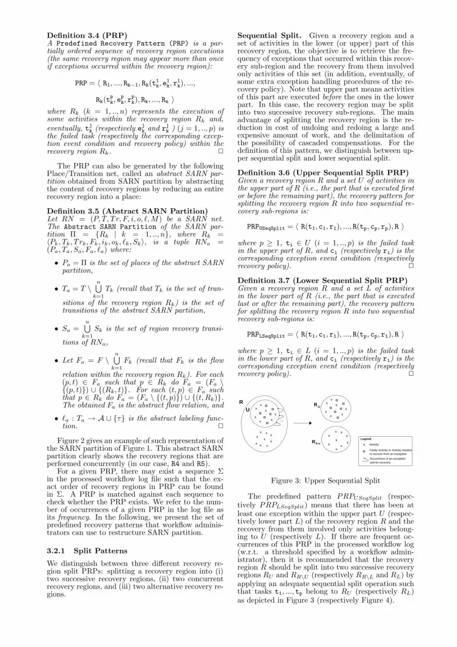
Figure 3: Upper Sequential Split
The predefined pattern PRPUSeqSplit (respec-tively PRPLSeqSplit) means that there has been atleast one exception within the upper part U (respec-tively lower part L) of the recovery region R and therecovery from them involved only activities belong-ing to U (respectively L). If there are frequent oc-currences of this PRP in the processed workflow log(w.r.t. a threshold specified by a workflow admin-istrator), then it is recommended that the recoveryregion R should be split into two successive recoveryregions RU and RR\U (respectively RR\L and RL) byapplying an adequate sequential split operation suchthat tasks t1, ..., tp belong to RU (respectively RL)as depicted in Figure 3 (respectively Figure 4).
x Ox
xO
xx O
O x
x
OO
...
x
x
x
x
x
Ox O
xx
O x
x
x
xx
x
x
OO
R L
RR-L
L
R
x x
x
xx
xx
x
O
x
x
O
Occurrence of an exceptionand its recovery
Activityx
Legend:
Faulty Activity or Activity neededto recover from an exception
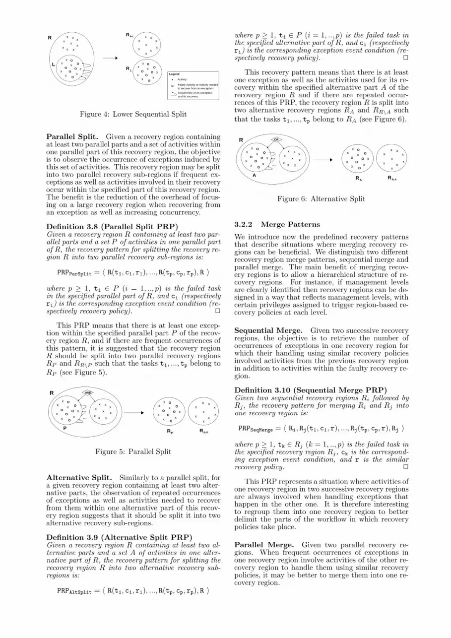
Figure 4: Lower Sequential Split
Parallel Split. Given a recovery region containingat least two parallel parts and a set of activities withinone parallel part of this recovery region, the objectiveis to observe the occurrence of exceptions induced bythis set of activities. This recovery region may be splitinto two parallel recovery sub-regions if frequent ex-ceptions as well as activities involved in their recoveryoccur within the specified part of this recovery region.The benefit is the reduction of the overhead of focus-ing on a large recovery region when recovering froman exception as well as increasing concurrency.
Definition 3.8 (Parallel Split PRP)Given a recovery region R containing at least two par-allel parts and a set P of activities in one parallel partof R, the recovery pattern for splitting the recovery re-gion R into two parallel recovery sub-regions is:
where p ≥ 1, ti ∈ P (i = 1, .., p) is the failed taskin the specified parallel part of R, and ci (respectivelyri) is the corresponding exception event condition (re-spectively recovery policy). 2
This PRP means that there is at least one excep-tion within the specified parallel part P of the recov-ery region R, and if there are frequent occurrences ofthis pattern, it is suggested that the recovery regionR should be split into two parallel recovery regionsRP and RR\P such that the tasks t1, ..., tp belong toRP (see Figure 5).
x Ox
xO
xx O
O x
x
OO
...
xx
x
xO
x O
xx
O x
x
x
xx
x
x
OO
R
x x
x
xx
xx
O
x
R-PRP
xx
x
R
P
AND
Figure 5: Parallel Split
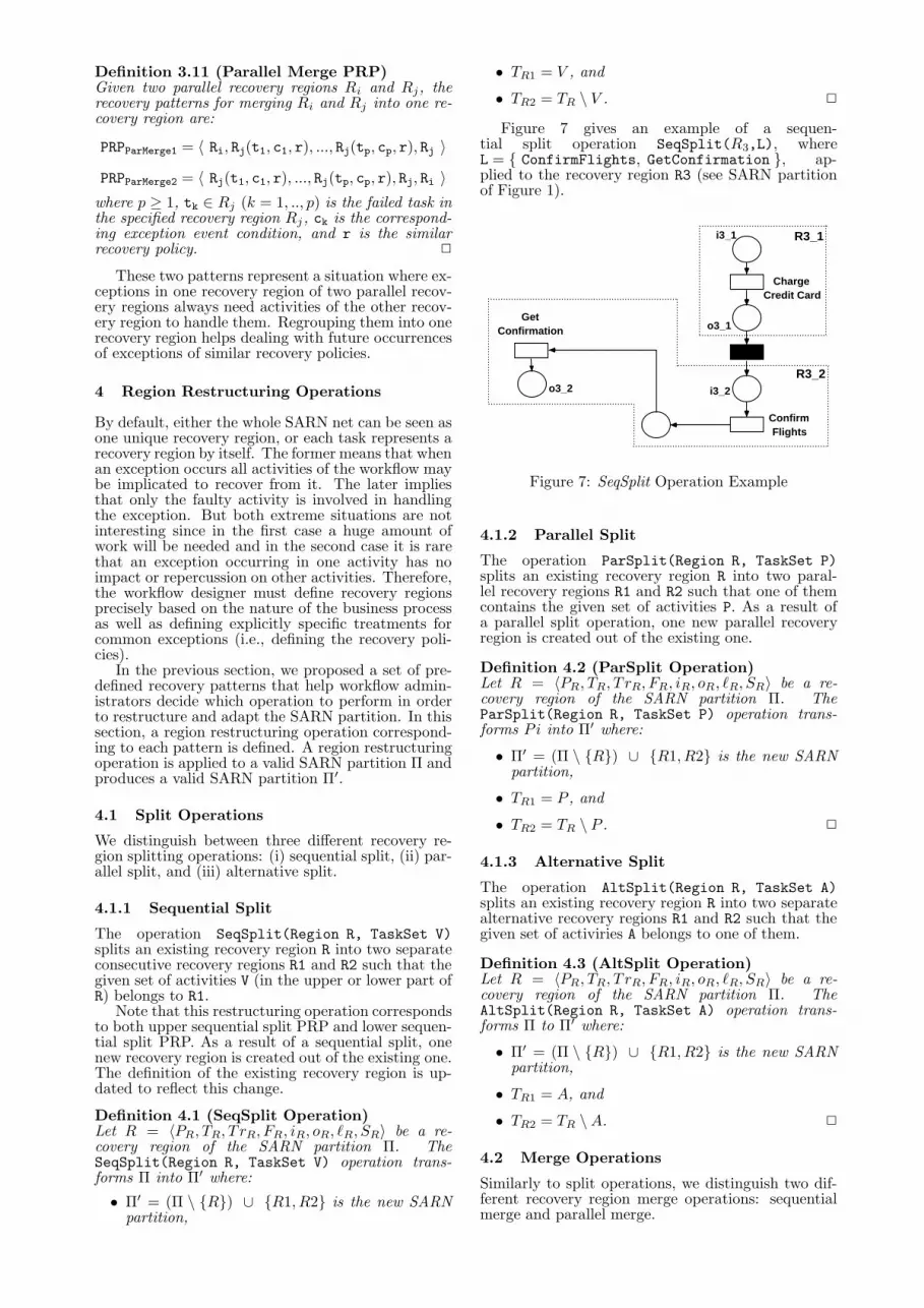
Alternative Split. Similarly to a parallel split, fora given recovery region containing at least two alter-native parts, the observation of repeated occurrencesof exceptions as well as activities needed to recoverfrom them within one alternative part of this recov-ery region suggests that it should be split it into twoalternative recovery sub-regions.
Definition 3.9 (Alternative Split PRP)Given a recovery region R containing at least two al-ternative parts and a set A of activities in one alter-native part of R, the recovery pattern for splitting therecovery region R into two alternative recovery sub-regions is:
where p ≥ 1, ti ∈ P (i = 1, .., p) is the failed task inthe specified alternative part of R, and ci (respectivelyri) is the corresponding exception event condition (re-spectively recovery policy). 2
This recovery pattern means that there is at leastone exception as well as the activities used for its re-covery within the specified alternative part A of therecovery region R and if there are repeated occur-rences of this PRP, the recovery region R is split intotwo alternative recovery regions RA and RR\A suchthat the tasks t1, ..., tp belong to RA (see Figure 6).
x Ox
xO
xx O
O x
x
OO
...
xx
x
xO
x O
xx
O x
x
x
xx
x
x
OO
R
x x
x
xx
xx
O
x
R
xx
x
ORR
AA R-A
Figure 6: Alternative Split
3.2.2 Merge Patterns
We introduce now the predefined recovery patternsthat describe situations where merging recovery re-gions can be beneficial. We distinguish two differentrecovery region merge patterns, sequential merge andparallel merge. The main benefit of merging recov-ery regions is to allow a hierarchical structure of re-covery regions. For instance, if management levelsare clearly identified then recovery regions can be de-signed in a way that reflects management levels, withcertain privileges assigned to trigger region-based re-covery policies at each level.
Sequential Merge. Given two successive recoveryregions, the objective is to retrieve the number ofoccurrences of exceptions in one recovery region forwhich their handling using similar recovery policiesinvolved activities from the previous recovery regionin addition to activities within the faulty recovery re-gion.
Definition 3.10 (Sequential Merge PRP)Given two sequential recovery regions Ri followed byRj , the recovery pattern for merging Ri and Rj intoone recovery region is:
where p ≥ 1, tk ∈ Rj (k = 1, .., p) is the failed task inthe specified recovery region Rj , ck is the correspond-ing exception event condition, and r is the similarrecovery policy. 2
This PRP represents a situation where activities ofone recovery region in two successive recovery regionsare always involved when handling exceptions thathappen in the other one. It is therefore interestingto regroup them into one recovery region to betterdelimit the parts of the workflow in which recoverypolicies take place.
Parallel Merge. Given two parallel recovery re-gions. When frequent occurrences of exceptions inone recovery region involve activities of the other re-covery region to handle them using similar recoverypolicies, it may be better to merge them into one re-covery region.
Definition 3.11 (Parallel Merge PRP)Given two parallel recovery regions Ri and Rj , therecovery patterns for merging Ri and Rj into one re-covery region are:
where p ≥ 1, tk ∈ Rj (k = 1, .., p) is the failed task inthe specified recovery region Rj , ck is the correspond-ing exception event condition, and r is the similarrecovery policy. 2
These two patterns represent a situation where ex-ceptions in one recovery region of two parallel recov-ery regions always need activities of the other recov-ery region to handle them. Regrouping them into onerecovery region helps dealing with future occurrencesof exceptions of similar recovery policies.
4 Region Restructuring Operations
By default, either the whole SARN net can be seen asone unique recovery region, or each task represents arecovery region by itself. The former means that whenan exception occurs all activities of the workflow maybe implicated to recover from it. The later impliesthat only the faulty activity is involved in handlingthe exception. But both extreme situations are notinteresting since in the first case a huge amount ofwork will be needed and in the second case it is rarethat an exception occurring in one activity has noimpact or repercussion on other activities. Therefore,the workflow designer must define recovery regionsprecisely based on the nature of the business processas well as defining explicitly specific treatments forcommon exceptions (i.e., defining the recovery poli-cies).
In the previous section, we proposed a set of pre-defined recovery patterns that help workflow admin-istrators decide which operation to perform in orderto restructure and adapt the SARN partition. In thissection, a region restructuring operation correspond-ing to each pattern is defined. A region restructuringoperation is applied to a valid SARN partition Π andproduces a valid SARN partition Π′.
4.1 Split Operations
We distinguish between three different recovery re-gion splitting operations: (i) sequential split, (ii) par-allel split, and (iii) alternative split.
4.1.1 Sequential Split
The operation SeqSplit(Region R, TaskSet V)splits an existing recovery region R into two separateconsecutive recovery regions R1 and R2 such that thegiven set of activities V (in the upper or lower part ofR) belongs to R1.
Note that this restructuring operation correspondsto both upper sequential split PRP and lower sequen-tial split PRP. As a result of a sequential split, onenew recovery region is created out of the existing one.The definition of the existing recovery region is up-dated to reflect this change.
Definition 4.1 (SeqSplit Operation)Let R = 〈PR, TR, T rR, FR, iR, oR, `R, SR〉 be a re-covery region of the SARN partition Π. TheSeqSplit(Region R, TaskSet V) operation trans-forms Π into Π′ where:
• Π′ = (Π \ {R}) ∪ {R1, R2} is the new SARNpartition,
• TR1 = V , and
• TR2 = TR \ V . 2
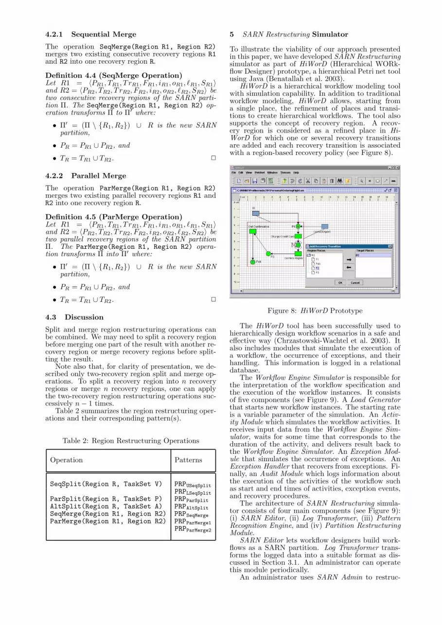
Figure 7 gives an example of a sequen-tial split operation SeqSplit(R3,L), whereL = { ConfirmFlights, GetConfirmation }, ap-plied to the recovery region R3 (see SARN partitionof Figure 1).
ConfirmFlights
GetConfirmation
ChargeCredit Card
i3_2o3_2
o3_1
i3_1 R3_1
R3_2
Figure 7: SeqSplit Operation Example
4.1.2 Parallel Split
The operation ParSplit(Region R, TaskSet P)splits an existing recovery region R into two paral-lel recovery regions R1 and R2 such that one of themcontains the given set of activities P. As a result ofa parallel split operation, one new parallel recoveryregion is created out of the existing one.
Definition 4.2 (ParSplit Operation)Let R = 〈PR, TR, T rR, FR, iR, oR, `R, SR〉 be a re-covery region of the SARN partition Π. TheParSplit(Region R, TaskSet P) operation trans-forms Pi into Π′ where:
• Π′ = (Π \ {R}) ∪ {R1, R2} is the new SARNpartition,
• TR1 = P , and
• TR2 = TR \ P . 2
4.1.3 Alternative Split
The operation AltSplit(Region R, TaskSet A)splits an existing recovery region R into two separatealternative recovery regions R1 and R2 such that thegiven set of activiries A belongs to one of them.
Definition 4.3 (AltSplit Operation)Let R = 〈PR, TR, T rR, FR, iR, oR, `R, SR〉 be a re-covery region of the SARN partition Π. TheAltSplit(Region R, TaskSet A) operation trans-forms Π to Π′ where:
• Π′ = (Π \ {R}) ∪ {R1, R2} is the new SARNpartition,
• TR1 = A, and
• TR2 = TR \ A. 2
4.2 Merge Operations
Similarly to split operations, we distinguish two dif-ferent recovery region merge operations: sequentialmerge and parallel merge.
4.2.1 Sequential Merge
The operation SeqMerge(Region R1, Region R2)merges two existing consecutive recovery regions R1and R2 into one recovery region R.
Definition 4.4 (SeqMerge Operation)Let R1 = 〈PR1, TR1, T rR1, FR1, iR1, oR1, `R1, SR1〉and R2 = 〈PR2, TR2, T rR2, FR2, iR2, oR2, `R2, SR2〉 betwo consecutive recovery regions of the SARN parti-tion Π. The SeqMerge(Region R1, Region R2) op-eration transforms Π to Π′ where:
• Π′ = (Π \ {R1, R2}) ∪ R is the new SARNpartition,
• PR = PR1 ∪ PR2, and
• TR = TR1 ∪ TR2. 2
4.2.2 Parallel Merge
The operation ParMerge(Region R1, Region R2)merges two existing parallel recovery regions R1 andR2 into one recovery region R.
Definition 4.5 (ParMerge Operation)Let R1 = 〈PR1, TR1, T rR1, FR1, iR1, oR1, `R1, SR1〉and R2 = 〈PR2, TR2, T rR2, FR2, iR2, oR2, `R2, SR2〉 betwo parallel recovery regions of the SARN partitionΠ. The ParMerge(Region R1, Region R2) opera-tion transforms Π into Π′ where:
• Π′ = (Π \ {R1, R2}) ∪ R is the new SARNpartition,
• PR = PR1 ∪ PR2, and
• TR = TR1 ∪ TR2. 2
4.3 Discussion
Split and merge region restructuring operations canbe combined. We may need to split a recovery regionbefore merging one part of the result with another re-covery region or merge recovery regions before split-ting the result.
Note also that, for clarity of presentation, we de-scribed only two-recovery region split and merge op-erations. To split a recovery region into n recoveryregions or merge n recovery regions, one can applythe two-recovery region restructuring operations suc-cessively n − 1 times.
Table 2 summarizes the region restructuring oper-ations and their corresponding pattern(s).
ParSplit(Region R, TaskSet P) PRPParSplitAltSplit(Region R, TaskSet A) PRPAltSplitSeqMerge(Region R1, Region R2) PRPSeqMergeParMerge(Region R1, Region R2) PRPParMerge1
PRPParMerge2
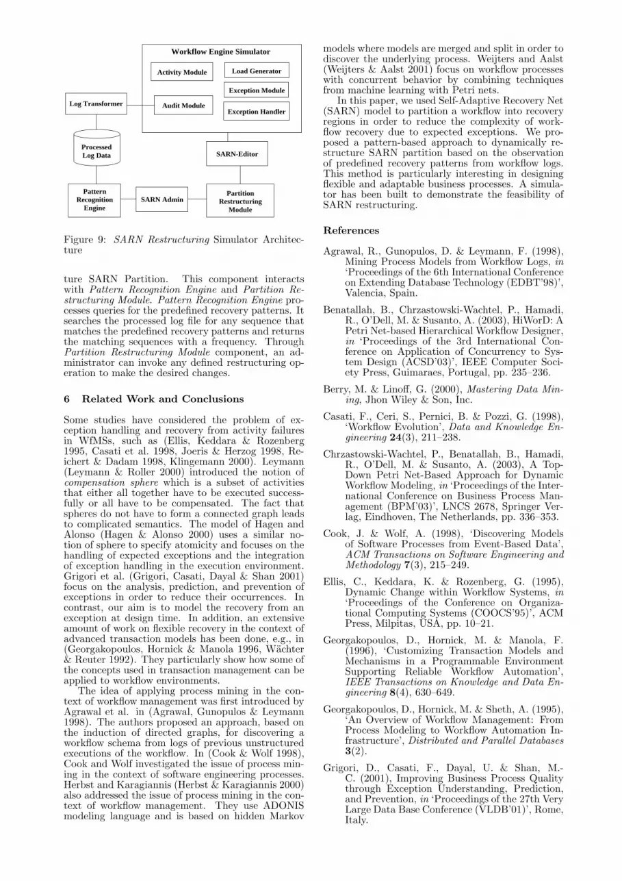
5 SARN Restructuring Simulator
To illustrate the viability of our approach presentedin this paper, we have developed SARN Restructuringsimulator as part of HiWorD (HIerarchical WORk-flow Designer) prototype, a hierarchical Petri net toolusing Java (Benatallah et al. 2003).
HiWorD is a hierarchical workflow modeling toolwith simulation capability. In addition to traditionalworkflow modeling, HiWorD allows, starting froma single place, the refinement of places and transi-tions to create hierarchical workflows. The tool alsosupports the concept of recovery region. A recov-ery region is considered as a refined place in Hi-WorD for which one or several recovery transitionsare added and each recovery transition is associatedwith a region-based recovery policy (see Figure 8).
Figure 8: HiWorD Prototype
The HiWorD tool has been successfully used tohierarchically design workflow scenarios in a safe andeffective way (Chrzastowski-Wachtel et al. 2003). Italso includes modules that simulate the execution ofa workflow, the occurrence of exceptions, and theirhandling. This information is logged in a relationaldatabase.
The Workflow Engine Simulator is responsible forthe interpretation of the workflow specification andthe execution of the workflow instances. It consistsof five components (see Figure 9). A Load Generatorthat starts new workflow instances. The starting rateis a variable parameter of the simulation. An Activ-ity Module which simulates the workflow activities. Itreceives input data from the Workflow Engine Sim-ulator, waits for some time that corresponds to theduration of the activity, and delivers result back tothe Workflow Engine Simulator. An Exception Mod-ule that simulates the occurrence of exceptions. AnException Handler that recovers from exceptions. Fi-nally, an Audit Module which logs information aboutthe execution of the activities of the workflow suchas start and end times of activities, exception events,and recovery procedures.
The architecture of SARN Restructuring simula-tor consists of four main components (see Figure 9):(i) SARN Editor, (ii) Log Transformer, (iii) PatternRecognition Engine, and (iv) Partition RestructuringModule.
SARN Editor lets workflow designers build work-flows as a SARN partition. Log Transformer trans-forms the logged data into a suitable format as dis-cussed in Section 3.1. An administrator can operatethis module periodically.
ture SARN Partition. This component interactswith Pattern Recognition Engine and Partition Re-structuring Module. Pattern Recognition Engine pro-cesses queries for the predefined recovery patterns. Itsearches the processed log file for any sequence thatmatches the predefined recovery patterns and returnsthe matching sequences with a frequency. ThroughPartition Restructuring Module component, an ad-ministrator can invoke any defined restructuring op-eration to make the desired changes.
6 Related Work and Conclusions
Some studies have considered the problem of ex-ception handling and recovery from activity failuresin WfMSs, such as (Ellis, Keddara & Rozenberg1995, Casati et al. 1998, Joeris & Herzog 1998, Re-ichert & Dadam 1998, Klingemann 2000). Leymann(Leymann & Roller 2000) introduced the notion ofcompensation sphere which is a subset of activitiesthat either all together have to be executed success-fully or all have to be compensated. The fact thatspheres do not have to form a connected graph leadsto complicated semantics. The model of Hagen andAlonso (Hagen & Alonso 2000) uses a similar no-tion of sphere to specify atomicity and focuses on thehandling of expected exceptions and the integrationof exception handling in the execution environment.Grigori et al. (Grigori, Casati, Dayal & Shan 2001)focus on the analysis, prediction, and prevention ofexceptions in order to reduce their occurrences. Incontrast, our aim is to model the recovery from anexception at design time. In addition, an extensiveamount of work on flexible recovery in the context ofadvanced transaction models has been done, e.g., in(Georgakopoulos, Hornick & Manola 1996, Wachter& Reuter 1992). They particularly show how some ofthe concepts used in transaction management can beapplied to workflow environments.
The idea of applying process mining in the con-text of workflow management was first introduced byAgrawal et al. in (Agrawal, Gunopulos & Leymann1998). The authors proposed an approach, based onthe induction of directed graphs, for discovering aworkflow schema from logs of previous unstructuredexecutions of the workflow. In (Cook & Wolf 1998),Cook and Wolf investigated the issue of process min-ing in the context of software engineering processes.Herbst and Karagiannis (Herbst & Karagiannis 2000)also addressed the issue of process mining in the con-text of workflow management. They use ADONISmodeling language and is based on hidden Markov
models where models are merged and split in order todiscover the underlying process. Weijters and Aalst(Weijters & Aalst 2001) focus on workflow processeswith concurrent behavior by combining techniquesfrom machine learning with Petri nets.
In this paper, we used Self-Adaptive Recovery Net(SARN) model to partition a workflow into recoveryregions in order to reduce the complexity of work-flow recovery due to expected exceptions. We pro-posed a pattern-based approach to dynamically re-structure SARN partition based on the observationof predefined recovery patterns from workflow logs.This method is particularly interesting in designingflexible and adaptable business processes. A simula-tor has been built to demonstrate the feasibility ofSARN restructuring.
References
Agrawal, R., Gunopulos, D. & Leymann, F. (1998),Mining Process Models from Workflow Logs, in‘Proceedings of the 6th International Conferenceon Extending Database Technology (EDBT’98)’,Valencia, Spain.
Benatallah, B., Chrzastowski-Wachtel, P., Hamadi,R., O’Dell, M. & Susanto, A. (2003), HiWorD: APetri Net-based Hierarchical Workflow Designer,in ‘Proceedings of the 3rd International Con-ference on Application of Concurrency to Sys-tem Design (ACSD’03)’, IEEE Computer Soci-ety Press, Guimaraes, Portugal, pp. 235–236.
Berry, M. & Linoff, G. (2000), Mastering Data Min-ing, Jhon Wiley & Son, Inc.
Casati, F., Ceri, S., Pernici, B. & Pozzi, G. (1998),‘Workflow Evolution’, Data and Knowledge En-gineering 24(3), 211–238.
Chrzastowski-Wachtel, P., Benatallah, B., Hamadi,R., O’Dell, M. & Susanto, A. (2003), A Top-Down Petri Net-Based Approach for DynamicWorkflow Modeling, in ‘Proceedings of the Inter-national Conference on Business Process Man-agement (BPM’03)’, LNCS 2678, Springer Ver-lag, Eindhoven, The Netherlands, pp. 336–353.
Cook, J. & Wolf, A. (1998), ‘Discovering Modelsof Software Processes from Event-Based Data’,ACM Transactions on Software Engineering andMethodology 7(3), 215–249.
Ellis, C., Keddara, K. & Rozenberg, G. (1995),Dynamic Change within Workflow Systems, in‘Proceedings of the Conference on Organiza-tional Computing Systems (COOCS’95)’, ACMPress, Milpitas, USA, pp. 10–21.
Georgakopoulos, D., Hornick, M. & Manola, F.(1996), ‘Customizing Transaction Models andMechanisms in a Programmable EnvironmentSupporting Reliable Workflow Automation’,IEEE Transactions on Knowledge and Data En-gineering 8(4), 630–649.
Georgakopoulos, D., Hornick, M. & Sheth, A. (1995),‘An Overview of Workflow Management: FromProcess Modeling to Workflow Automation In-frastructure’, Distributed and Parallel Databases3(2).
Grigori, D., Casati, F., Dayal, U. & Shan, M.-C. (2001), Improving Business Process Qualitythrough Exception Understanding, Prediction,and Prevention, in ‘Proceedings of the 27th VeryLarge Data Base Conference (VLDB’01)’, Rome,Italy.
Hagen, C. & Alonso, G. (2000), ‘Exception Han-dling in Workflow Management Systems’, IEEETransactions on Software Engineering (TSE)26(10), 943–958.
Hamadi, R. & Benatallah, B. (2004), Recovery Nets:Towards Self-Adaptive Workfow Systems, in‘Proceedings of the 5th International Confer-ence on Web Information Systems Engineering(WISE’04)’, LNCS 3306, Springer Verlag, Bris-bane, Australia, pp. 439–453.
Herbst, J. & Karagiannis, D. (2000), ‘Integrating Ma-chine Learning and Workflow Management toSupport Acquisition and Adaption of WorkflowModels’, International Journal of intelligent Sys-tems in Accounting, Finance and Management9, 67–92.
Joeris, G. & Herzog, O. (1998), Managing EvolvingWorkflow Specifications, in ‘Proceedings of the3rd Conference on Cooperative Information Sys-tems (CoopIS’98)’, New York, USA.
Klingemann, J. (2000), Controlled Flexibility inWorkflow Management, in ‘Proceedings of the12th Conference on Advanced Information Sys-tems Engineering (CAiSE’00)’, Stockholm, Swe-den.
Leymann, F. & Roller, D. (2000), Production Work-flow — Concepts and Techniques, Prentice Hall.
Murata, T. (1989), Petri Nets: Properties, Analysisand Applications, in ‘Proceedings of the IEEE’,Vol. 77(4), pp. 541–580.
Peterson, J. (1981), Petri Net Theory and the Model-ing of Systems, Prentice Hall, Englewood Cliffs.
Reichert, M. & Dadam, P. (1998), ‘ADEPT flex: Sup-porting Dynamic Changes of Workflows withoutLosing Control’, Journal of Intelligent Informa-tion Systems 10(2), 93–129.
Wachter, H. & Reuter, A. (1992), The ConTractModel, in A. Elmagarmid, ed., ‘Database Trans-action Models for Advanced Applications’, Mor-gan Kaufmann, pp. 219–264.
Weijters, A. & Aalst, W. v. d. (2001), Process Mining.Discovering Workflow Models from Event-BasedData, in B. Krse, M. De Rijke, G. Schreiber &M. v. Someren, eds, ‘Proceedings of the 13thBelgium-Netherlands Conference on ArtificialIntelligence (BNAIC’01)’, Maastricht, Nether-lands, pp. 283–290.
WfMC (1999), Workflow ManagementCoalition, Terminology and Glossary,Document Number WFMC-TC-1011.http://www.wfmc.org/standards/docs.htm/.