22
Bowl feeder BF20 / BF25 / BF30 BF35 / BF40 / BF50 Translation of operating and installation instructions Copyright by Afag GmbH
| Date post: | 30-Nov-2023 |
| Category: |
Documents |
| Upload: | khangminh22 |
| View: | 0 times |
| Download: | 0 times |
Bowl feeder
BF20 / BF25 / BF30 BF35 / BF40 / BF50
Translation of operating and installation instructions
Copyright by Afag GmbH
Page 2 07.07.2022 R06.4
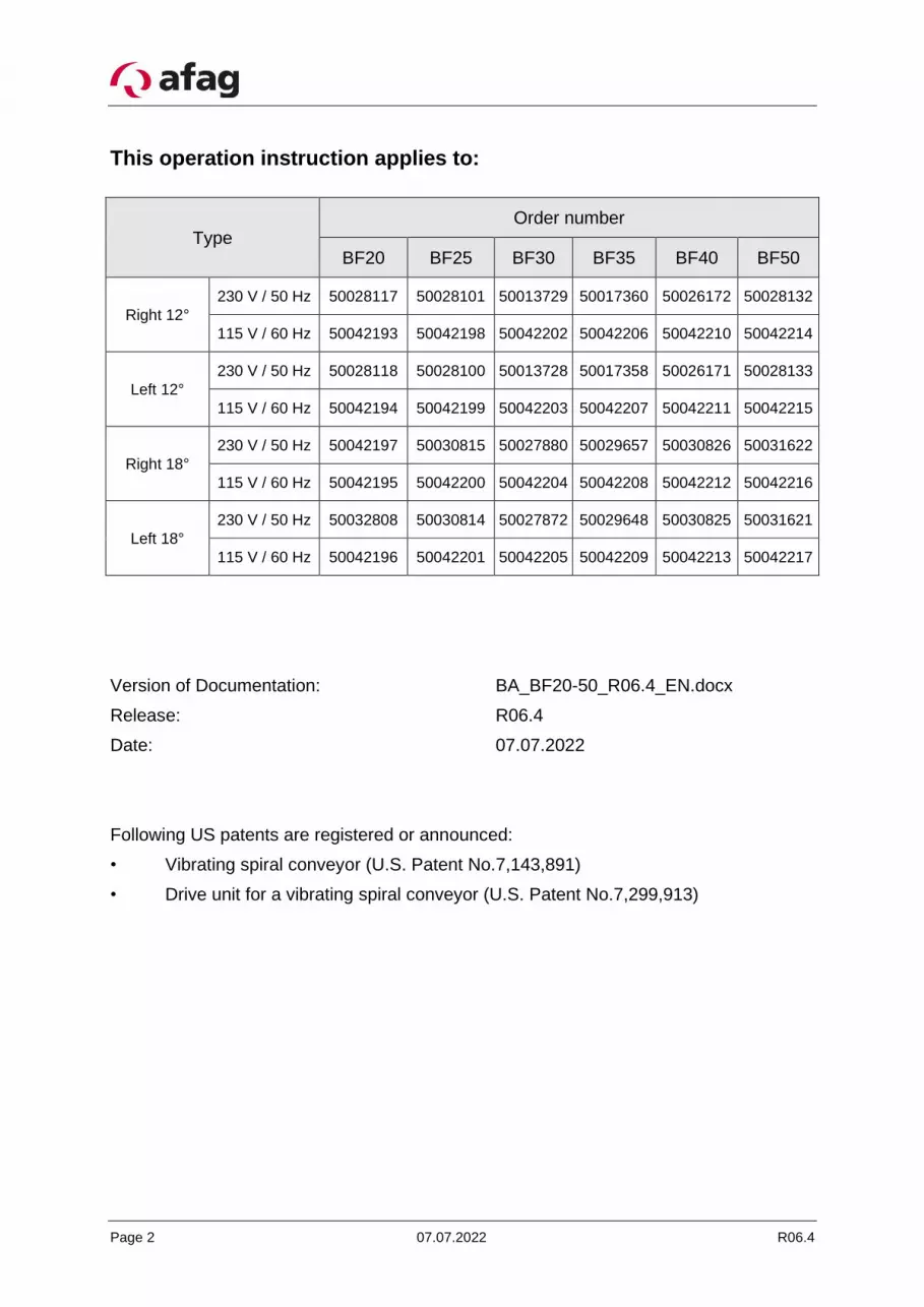
This operation instruction applies to:
Type Order number
BF20 BF25 BF30 BF35 BF40 BF50
Right 12°
230 V / 50 Hz 50028117 50028101 50013729 50017360 50026172 50028132
115 V / 60 Hz 50042193 50042198 50042202 50042206 50042210 50042214
Left 12°
230 V / 50 Hz 50028118 50028100 50013728 50017358 50026171 50028133
115 V / 60 Hz 50042194 50042199 50042203 50042207 50042211 50042215
Right 18°
230 V / 50 Hz 50042197 50030815 50027880 50029657 50030826 50031622
115 V / 60 Hz 50042195 50042200 50042204 50042208 50042212 50042216
Left 18°
230 V / 50 Hz 50032808 50030814 50027872 50029648 50030825 50031621
115 V / 60 Hz 50042196 50042201 50042205 50042209 50042213 50042217
Version of Documentation: BA_BF20-50_R06.4_EN.docx
Release: R06.4
Date: 07.07.2022
Following US patents are registered or announced:
• Vibrating spiral conveyor (U.S. Patent No.7,143,891)
• Drive unit for a vibrating spiral conveyor (U.S. Patent No.7,299,913)

R06.4 07.07.2022 Page 3
Table of contents:
1 Safety instructions ................................................................................................. 4
1.1 Notes on symbols and instructions ........................................................................................................ 4
1.2 Basic safety information ........................................................................................................................ 5
1.3 Appropriate use ..................................................................................................................................... 5
1.4 Notes for Pacemakers and Defibrillators ............................................................................................... 6
2 Description of the device ....................................................................................... 6
2.1 General .................................................................................................................................................. 6
2.2 Function description .............................................................................................................................. 7
2.3 Definition of the feed direction .............................................................................................................. 7
2.4 Technical data ....................................................................................................................................... 8
3 Assembly instructions ......................................................................................... 10
3.1 Transport ............................................................................................................................................. 10
3.2 Installing the unit ................................................................................................................................. 10
3.3 Fixing the bowl ..................................................................................................................................... 11 3.3.1 Central Fixing .............................................................................................................................. 11 3.3.2 Radial Fixing ................................................................................................................................ 12
3.4 Power supply ....................................................................................................................................... 13
4 Operating instructions ......................................................................................... 14
4.1 Standard operation .............................................................................................................................. 14
4.2 Settings for the specific device ............................................................................................................. 14
4.3 Torques ................................................................................................................................................ 16
5 Maintenance instructions .................................................................................... 17
5.1 Replacing the leaf springs .................................................................................................................... 17
5.2 Adjusting the magnet gap ................................................................................................................... 18
5.3 Wear parts and Spare parts ................................................................................................................. 19
6 Accessories .......................................................................................................... 21
6.1 Adjusting tools ..................................................................................................................................... 21
6.2 Controller ............................................................................................................................................. 21
6.3 Address for orders................................................................................................................................ 22
7 Disposal ................................................................................................................ 22

Page 4 07.07.2022 R06.4
1 Safety instructions
1.1 Notes on symbols and instructions
Symbols: Assembly and commissioning must be carried out by qualified person-nel only and according to these operating instructions.
Please observe the meaning of the following symbols and notes. They are grouped into risk levels and classified according to ISO 3864-2.
DANGER
Indicates an immediate threatening danger.
Non-compliance with this information can result in death or seri-ous personal injuries (invalidity).
WARNING
Indicates a possible dangerous situation.
Non-compliance with this information can result in death or seri-ous personal injuries (invalidity).
CAUTION
Indicates a possibly dangerous situation.
Non-compliance with this information can result in damage to property or light to medium personal injuries.
NOTE
Indicates general notes, useful operator tips and operating rec-ommendations which don’t affect safety and health of the person-nel.

R06.4 07.07.2022 Page 5
1.2 Basic safety information
These operating instructions provide the information operators require to use the BF bowl feeder safely. These operating instructions, and in particular the safety information, must be observed by anyone working on and with the BF. The applicable on-site acci-dent prevention rules and regulations must also be observed.
These operating instructions must always be kept ready to hand where the BF is operat-ed.
1.3 Appropriate use
Afag BF bowl feeders are designed only for storing, transporting, separating and sorting workpieces of varying dimensions, shapes and material variants. Appropriate use also includes observation of all Notes in these operating instructions.
WARNING
The BF may not be used:
a) in damply and wet area
b) in temperature lower than 10°C or higher than 45°C
c) in areas where readily flammable media are present
d) in areas where readily explosive media are present
e) in heavy polluted or dust- laden area
f) in aggressive area (e.g. saliferous atmosphere)
None modification or reconstruction are allowed. The operations described in chapter 3.3 Fixing the bowl and in chapter 4.1 Standard operation are excluded from this arrange-ment.
NOTE
Any other use is inappropriate and will result in the warranty be-coming null and void.
See also our General Terms of Business.
Page 6 07.07.2022 R06.4
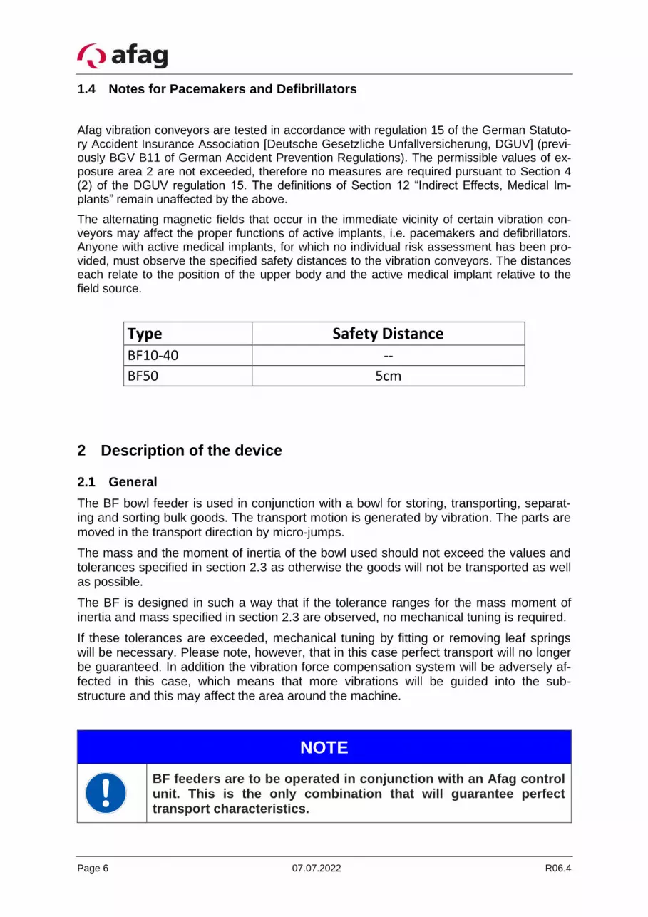
1.4 Notes for Pacemakers and Defibrillators
Afag vibration conveyors are tested in accordance with regulation 15 of the German Statuto-ry Accident Insurance Association [Deutsche Gesetzliche Unfallversicherung, DGUV] (previ-ously BGV B11 of German Accident Prevention Regulations). The permissible values of ex-posure area 2 are not exceeded, therefore no measures are required pursuant to Section 4 (2) of the DGUV regulation 15. The definitions of Section 12 “Indirect Effects, Medical Im-plants” remain unaffected by the above.
The alternating magnetic fields that occur in the immediate vicinity of certain vibration con-veyors may affect the proper functions of active implants, i.e. pacemakers and defibrillators. Anyone with active medical implants, for which no individual risk assessment has been pro-vided, must observe the specified safety distances to the vibration conveyors. The distances each relate to the position of the upper body and the active medical implant relative to the field source.
Type Safety Distance BF10-40 --
BF50 5cm
2 Description of the device
2.1 General
The BF bowl feeder is used in conjunction with a bowl for storing, transporting, separat-ing and sorting bulk goods. The transport motion is generated by vibration. The parts are moved in the transport direction by micro-jumps.
The mass and the moment of inertia of the bowl used should not exceed the values and tolerances specified in section 2.3 as otherwise the goods will not be transported as well as possible.
The BF is designed in such a way that if the tolerance ranges for the mass moment of inertia and mass specified in section 2.3 are observed, no mechanical tuning is required.
If these tolerances are exceeded, mechanical tuning by fitting or removing leaf springs will be necessary. Please note, however, that in this case perfect transport will no longer be guaranteed. In addition the vibration force compensation system will be adversely af-fected in this case, which means that more vibrations will be guided into the sub-structure and this may affect the area around the machine.
NOTE
BF feeders are to be operated in conjunction with an Afag control unit. This is the only combination that will guarantee perfect transport characteristics.
R06.4 07.07.2022 Page 7
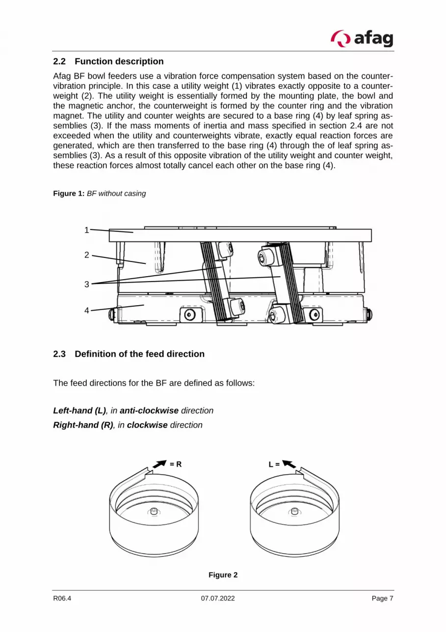
2.2 Function description
Afag BF bowl feeders use a vibration force compensation system based on the counter-vibration principle. In this case a utility weight (1) vibrates exactly opposite to a counter-weight (2). The utility weight is essentially formed by the mounting plate, the bowl and the magnetic anchor, the counterweight is formed by the counter ring and the vibration magnet. The utility and counter weights are secured to a base ring (4) by leaf spring as-semblies (3). If the mass moments of inertia and mass specified in section 2.4 are not exceeded when the utility and counterweights vibrate, exactly equal reaction forces are generated, which are then transferred to the base ring (4) through the of leaf spring as-semblies (3). As a result of this opposite vibration of the utility weight and counter weight, these reaction forces almost totally cancel each other on the base ring (4).
Figure 1: BF without casing
2.3 Definition of the feed direction
The feed directions for the BF are defined as follows:
Left-hand (L), in anti-clockwise direction
Right-hand (R), in clockwise direction
Figure 2
1
2
4
3
Page 8 07.07.2022 R06.4
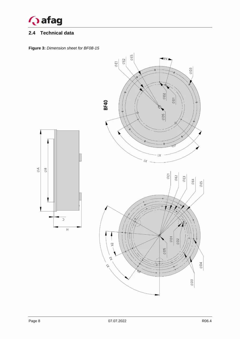
2.4 Technical data
Figure 3: Dimension sheet for BF08-15
R06.4 07.07.2022 Page 9
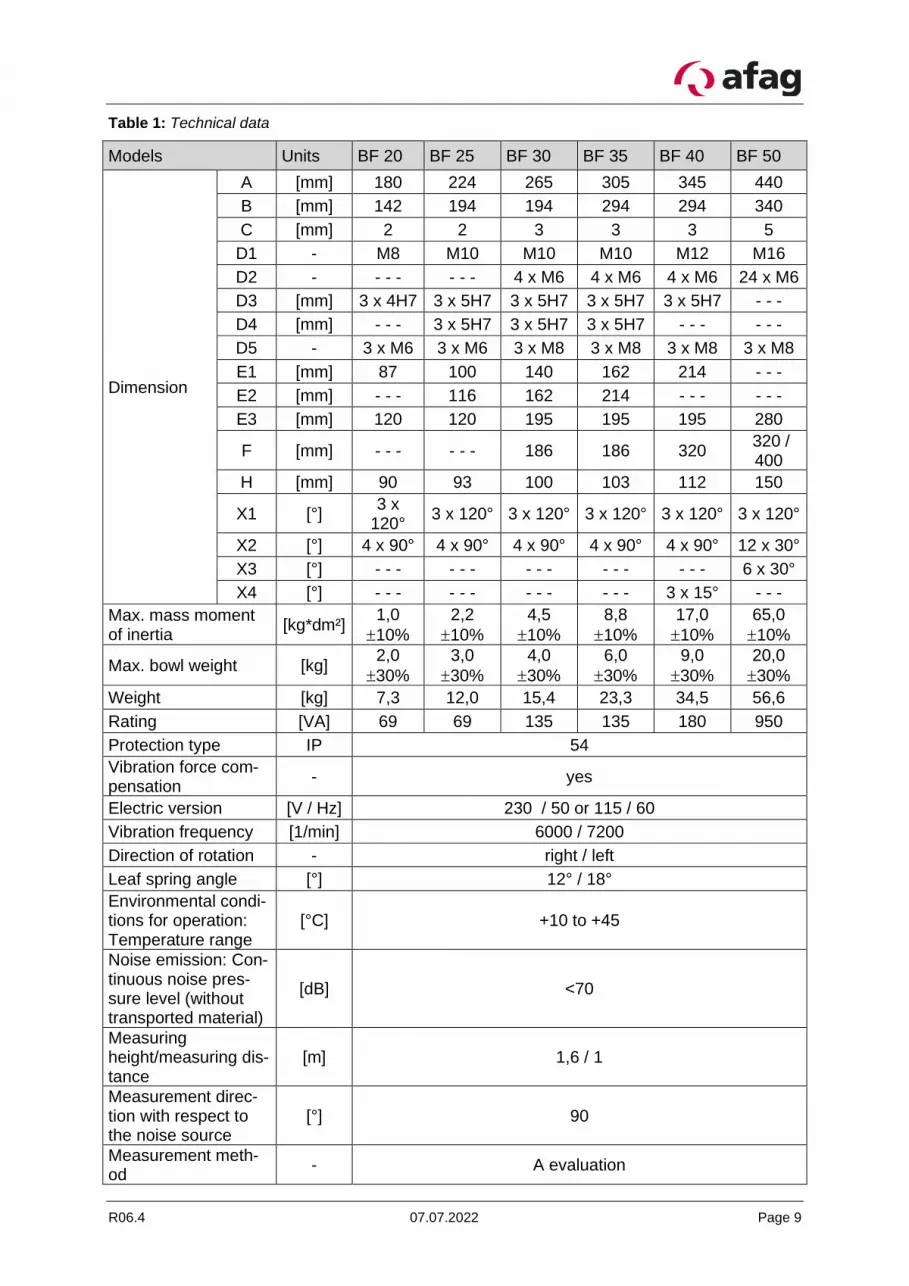
Table 1: Technical data
Models Units BF 20 BF 25 BF 30 BF 35 BF 40 BF 50
Dimension
A [mm] 180 224 265 305 345 440
B [mm] 142 194 194 294 294 340
C [mm] 2 2 3 3 3 5
D1 - M8 M10 M10 M10 M12 M16
D2 - - - - - - - 4 x M6 4 x M6 4 x M6 24 x M6
D3 [mm] 3 x 4H7 3 x 5H7 3 x 5H7 3 x 5H7 3 x 5H7 - - -
D4 [mm] - - - 3 x 5H7 3 x 5H7 3 x 5H7 - - - - - -
D5 - 3 x M6 3 x M6 3 x M8 3 x M8 3 x M8 3 x M8
E1 [mm] 87 100 140 162 214 - - -
E2 [mm] - - - 116 162 214 - - - - - -
E3 [mm] 120 120 195 195 195 280
F [mm] - - - - - - 186 186 320 320 / 400
H [mm] 90 93 100 103 112 150
X1 [°] 3 x
120° 3 x 120° 3 x 120° 3 x 120° 3 x 120° 3 x 120°
X2 [°] 4 x 90° 4 x 90° 4 x 90° 4 x 90° 4 x 90° 12 x 30°
X3 [°] - - - - - - - - - - - - - - - 6 x 30°
X4 [°] - - - - - - - - - - - - 3 x 15° - - -
Max. mass moment of inertia
[kg*dm²] 1,0
10%
2,2
10%
4,5
10%
8,8
10%
17,0
10%
65,0
10%
Max. bowl weight [kg] 2,0
30%
3,0
30%
4,0
30%
6,0
30%
9,0
30%
20,0
30%
Weight [kg] 7,3 12,0 15,4 23,3 34,5 56,6
Rating [VA] 69 69 135 135 180 950
Protection type IP 54
Vibration force com-pensation
- yes
Electric version [V / Hz] 230 / 50 or 115 / 60
Vibration frequency [1/min] 6000 / 7200
Direction of rotation - right / left
Leaf spring angle [°] 12° / 18°
Environmental condi-tions for operation: Temperature range
[°C] +10 to +45
Noise emission: Con-tinuous noise pres-sure level (without transported material)
[dB] <70
Measuring height/measuring dis-tance
[m] 1,6 / 1
Measurement direc-tion with respect to the noise source
[°] 90
Measurement meth-od
- A evaluation

Page 10 07.07.2022 R06.4
3 Assembly instructions
3.1 Transport
WARNING
Improper use of transport means (industrial trucks, cranes, tech-nical aids, sling gear etc.) may lead to bruises and other injuries.
Required behaviour:
- Observe and follow the transport and maintenance instruc-tions
- Proper use of transport means
CAUTION
Only handle the bowl feeder by its base ring during transport. Nei-ther the bowl nor the control elements may be used to lift the feeder.
3.2 Installing the unit
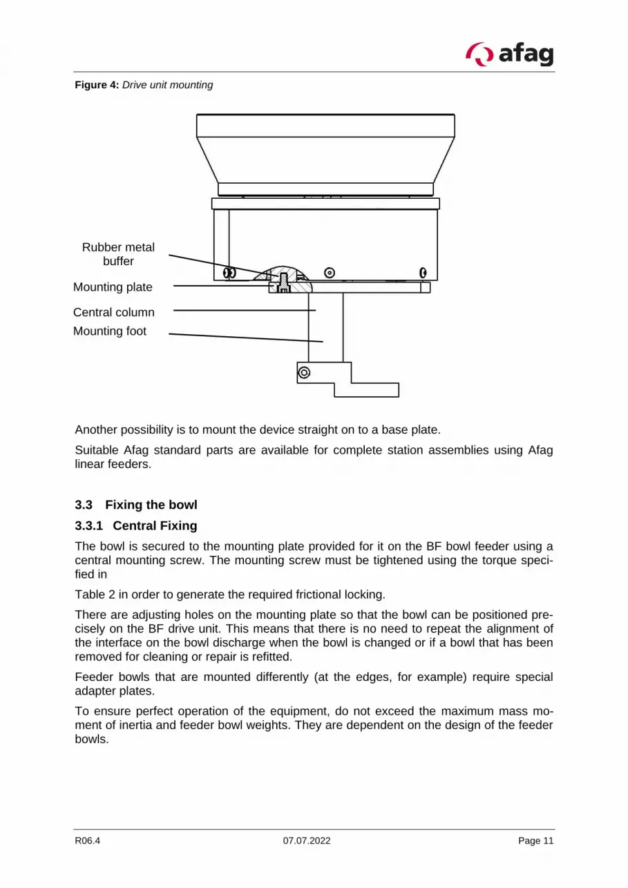
Each BF has 3 rubber-metal buffers so that the bowl feeder can be fastened to the sub-structure (see Figure 4). See section 2.4, Table 1, for the mounting hole dimensions.
Ideally the devices must be mounted on a plate that can be height-adjusted and rotated around a central column. Suitable substructure components are available from Afag.
R06.4 07.07.2022 Page 11
Figure 4: Drive unit mounting
Another possibility is to mount the device straight on to a base plate.
Suitable Afag standard parts are available for complete station assemblies using Afag linear feeders.
3.3 Fixing the bowl
3.3.1 Central Fixing
The bowl is secured to the mounting plate provided for it on the BF bowl feeder using a central mounting screw. The mounting screw must be tightened using the torque speci-fied in
Table 2 in order to generate the required frictional locking.
There are adjusting holes on the mounting plate so that the bowl can be positioned pre-cisely on the BF drive unit. This means that there is no need to repeat the alignment of the interface on the bowl discharge when the bowl is changed or if a bowl that has been removed for cleaning or repair is refitted.
Feeder bowls that are mounted differently (at the edges, for example) require special adapter plates.
To ensure perfect operation of the equipment, do not exceed the maximum mass mo-ment of inertia and feeder bowl weights. They are dependent on the design of the feeder bowls.
Rubber metal buffer
Mounting plate
Central column
Mounting foot
Page 12 07.07.2022 R06.4
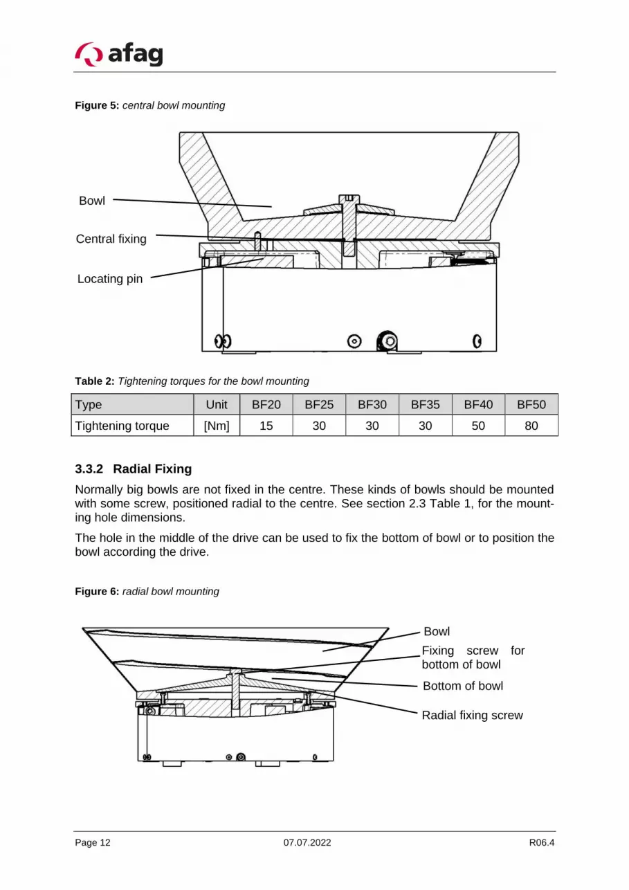
Figure 5: central bowl mounting
Table 2: Tightening torques for the bowl mounting
Type Unit BF20 BF25 BF30 BF35 BF40 BF50
Tightening torque [Nm] 15 30 30 30 50 80
3.3.2 Radial Fixing
Normally big bowls are not fixed in the centre. These kinds of bowls should be mounted with some screw, positioned radial to the centre. See section 2.3 Table 1, for the mount-ing hole dimensions.
The hole in the middle of the drive can be used to fix the bottom of bowl or to position the bowl according the drive.
Figure 6: radial bowl mounting
Central fixing
Bowl
Locating pin
Bowl
Fixing screw for bottom of bowl Bottom of bowl
Radial fixing screw
Fixing screw for bottom of bowl
R06.4 07.07.2022 Page 13
3.4 Power supply
WARNING
▪ Any work performed on the electrical supply may only be performed by trained, authorised, qualified personnel!
▪ The power supply must be protected by an FI switch (pro-vided by the customer).
▪ The bowl feeder may only be operated with the power sup-ply specified on the name plate.
The control device IRG1-S is used for the activation of the bowl feeder.
For the large drives BF50 with 115V mains voltage a suitable control unit with 12A RMS load capacity must be used instead of the IRG1-S.
The MSG801 or MSG802 can also be used. Please note that an additional CEE con-nector plug is required for the MSG controllers (Order number: 11006982)
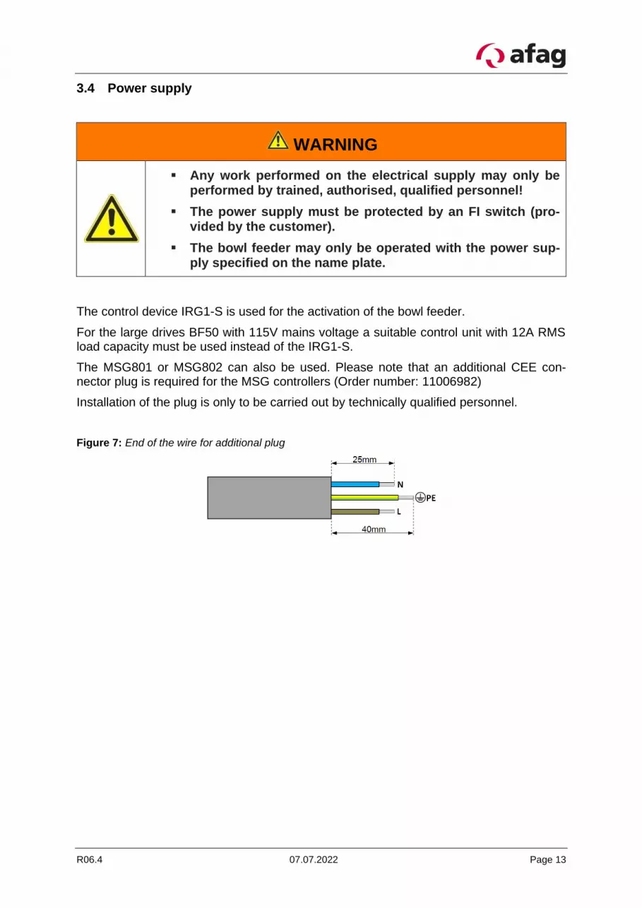
Installation of the plug is only to be carried out by technically qualified personnel.
Figure 7: End of the wire for additional plug
Page 14 07.07.2022 R06.4
4 Operating instructions
4.1 Standard operation
No further settings are required for standard operation once the control is switched on. An uninterrupted operation only requires the re-filling of the feeder bowl.
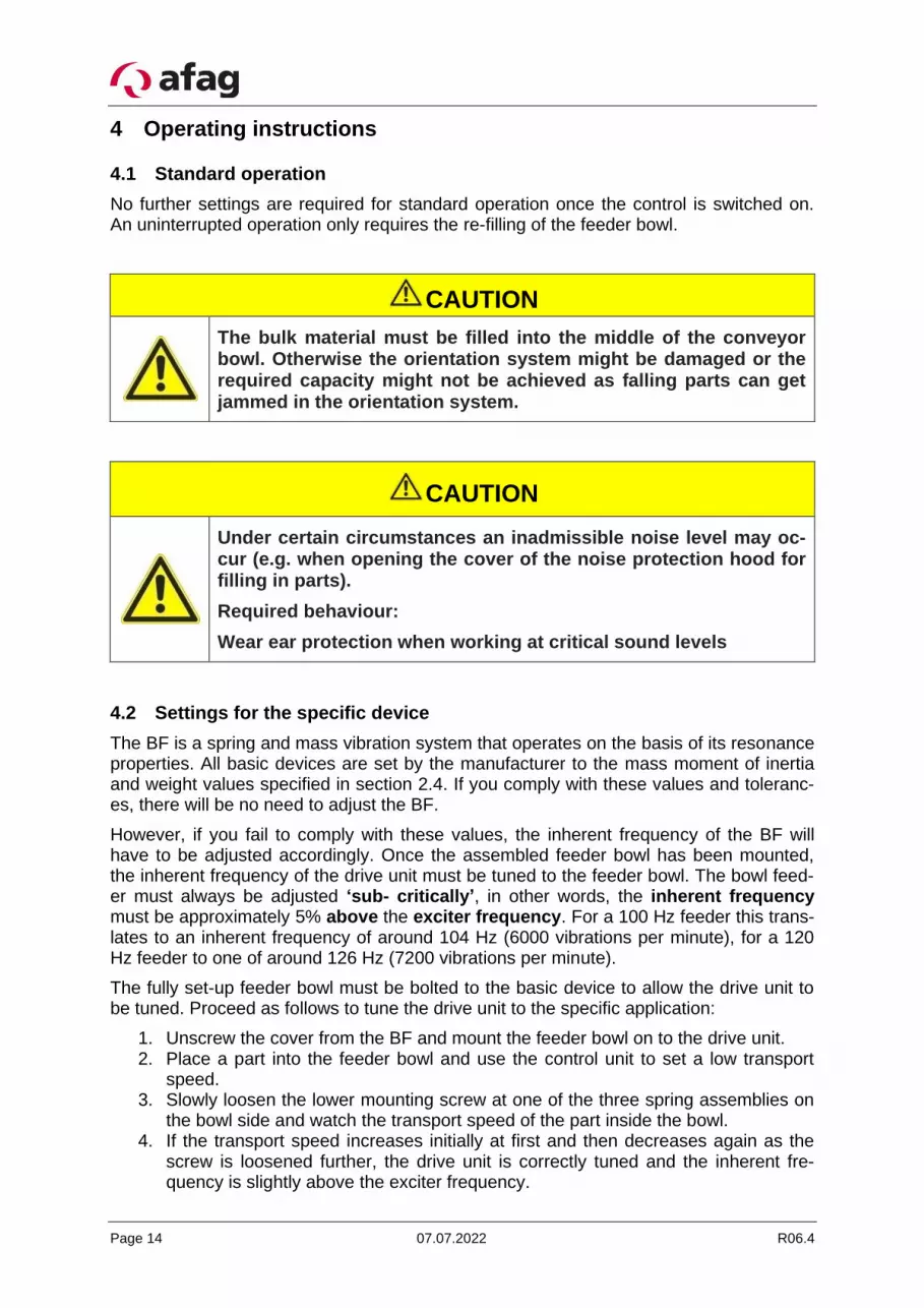
CAUTION
The bulk material must be filled into the middle of the conveyor bowl. Otherwise the orientation system might be damaged or the required capacity might not be achieved as falling parts can get jammed in the orientation system.
CAUTION
Under certain circumstances an inadmissible noise level may oc-cur (e.g. when opening the cover of the noise protection hood for filling in parts).
Required behaviour:
Wear ear protection when working at critical sound levels
4.2 Settings for the specific device
The BF is a spring and mass vibration system that operates on the basis of its resonance properties. All basic devices are set by the manufacturer to the mass moment of inertia and weight values specified in section 2.4. If you comply with these values and toleranc-es, there will be no need to adjust the BF.
However, if you fail to comply with these values, the inherent frequency of the BF will have to be adjusted accordingly. Once the assembled feeder bowl has been mounted, the inherent frequency of the drive unit must be tuned to the feeder bowl. The bowl feed-er must always be adjusted ‘sub- critically’, in other words, the inherent frequency must be approximately 5% above the exciter frequency. For a 100 Hz feeder this trans-lates to an inherent frequency of around 104 Hz (6000 vibrations per minute), for a 120 Hz feeder to one of around 126 Hz (7200 vibrations per minute).
The fully set-up feeder bowl must be bolted to the basic device to allow the drive unit to be tuned. Proceed as follows to tune the drive unit to the specific application:
1. Unscrew the cover from the BF and mount the feeder bowl on to the drive unit. 2. Place a part into the feeder bowl and use the control unit to set a low transport
speed. 3. Slowly loosen the lower mounting screw at one of the three spring assemblies on
the bowl side and watch the transport speed of the part inside the bowl. 4. If the transport speed increases initially at first and then decreases again as the
screw is loosened further, the drive unit is correctly tuned and the inherent fre-quency is slightly above the exciter frequency.
R06.4 07.07.2022 Page 15
5. If the transport speed only increases when the screw is loosened and does not decrease again even when the screw is fully loosened, the drive unit is too rigidly tuned. In this case, remove a leaf spring and retune the frequency. You must re-move as many leaf springs as necessary until the properties described in point 4) are achieved. If you have to remove several leaf springs, they must be removed as evenly as possible from the three spring assemblies on the bowl side.
6. If the transport speed decreases immediately while the screw is being loosened, the drive unit is tuned too softly. In this case, fit a leaf spring and retune the fre-quency. You must add as many leaf springs as necessary until the properties de-scribed in point 4) are achieved. If you have to add several leaf springs, they must be added as evenly as possible to the three spring assemblies on the bowl side. The fitted leaf springs must be clean and dry.
Only one spring assembly must be dismantled at a time. To tighten the screw after tuning the bowl feeder, apply the appropriate installation tool (see section 0, Table 7: Adjusting tools) in order to prevent the bowl feeder from twisting. The spring assemblies connected to the counter weight must not be loosened.
After you have adjusted the natural frequency, the magnet gap must be checked.This can easily become maladjusted whilst you are fitting or removing springs. If this is the case the magnet gap must be reset as described in section 5.2 Adjusting the magnet gap
Page 16 07.07.2022 R06.4
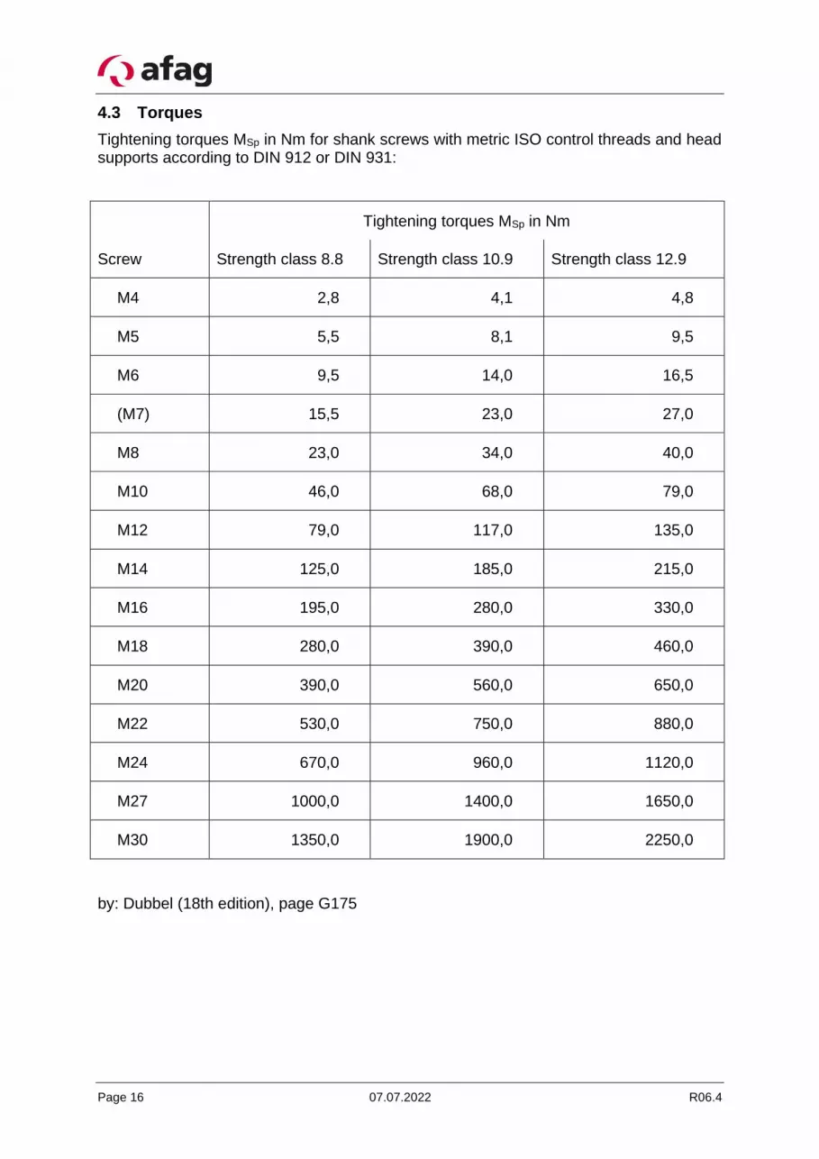
4.3 Torques
Tightening torques MSp in Nm for shank screws with metric ISO control threads and head supports according to DIN 912 or DIN 931:
Tightening torques MSp in Nm
Screw Strength class 8.8 Strength class 10.9 Strength class 12.9
M4 2,8 4,1 4,8
M5 5,5 8,1 9,5
M6 9,5 14,0 16,5
(M7) 15,5 23,0 27,0
M8 23,0 34,0 40,0
M10 46,0 68,0 79,0
M12 79,0 117,0 135,0
M14 125,0 185,0 215,0
M16 195,0 280,0 330,0
M18 280,0 390,0 460,0
M20 390,0 560,0 650,0
M22 530,0 750,0 880,0
M24 670,0 960,0 1120,0
M27 1000,0 1400,0 1650,0
M30 1350,0 1900,0 2250,0
by: Dubbel (18th edition), page G175

R06.4 07.07.2022 Page 17
5 Maintenance instructions
A type BF bowl feeder essentially requires no servicing. The leaf springs, however, may oxidize in certain conditions of use, thus affecting the vibration behavior in the long run. In these cases the leaf springs must be removed and cleaned or be changed. In rare cases the leaf springs must be completely replaced. 5.1 Replacing the leaf springs
Only one spring assembly may be dismantled at a time when removing the leaf springs. Before undoing the screws the centering brackets (Table 7: Adjusting tools) must be se-cured to the drive unit (see Figure 8). These secure the counterweight and mounting plate and thus prevent these parts sagging or moving.
CAUTION
The leaf springs must not be oiled or greased as this would make the springs sticky and in turn adversely affect the vibration re-sponse.
The number of leaf springs in a spring assembly and the structure of the spring assembly installed must be identical to the original spring assembly. Only then will the device func-tion correctly.
Figure 8: Spring assembly and centring bracket
The screws must be tightened using the torque shown in Table 3. During tightening the screws the spacer washers may not be turned.
Table 3: Tightening torques for spring installation
Type Unit BF20 BF25 BF30 BF35 BF40 BF50
Tightening torque [Nm] 40 40 79 79 79 135
Spacer washer
Leaf spring
Centring bracket
Leaf spring
Centring bracket
Page 18 07.07.2022 R06.4
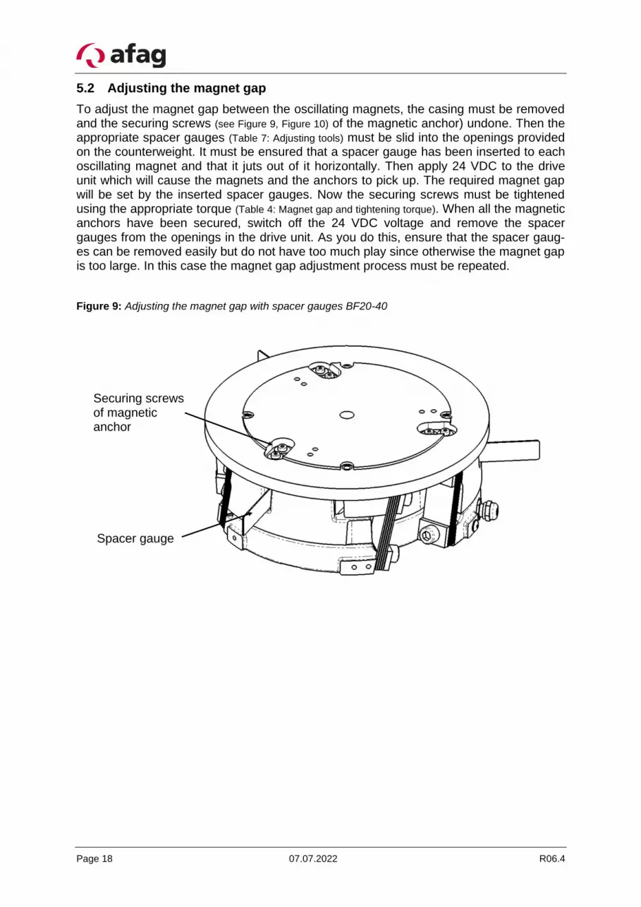
5.2 Adjusting the magnet gap
To adjust the magnet gap between the oscillating magnets, the casing must be removed and the securing screws (see Figure 9, Figure 10) of the magnetic anchor) undone. Then the appropriate spacer gauges (Table 7: Adjusting tools) must be slid into the openings provided on the counterweight. It must be ensured that a spacer gauge has been inserted to each oscillating magnet and that it juts out of it horizontally. Then apply 24 VDC to the drive unit which will cause the magnets and the anchors to pick up. The required magnet gap will be set by the inserted spacer gauges. Now the securing screws must be tightened using the appropriate torque (Table 4: Magnet gap and tightening torque). When all the magnetic anchors have been secured, switch off the 24 VDC voltage and remove the spacer gauges from the openings in the drive unit. As you do this, ensure that the spacer gaug-es can be removed easily but do not have too much play since otherwise the magnet gap is too large. In this case the magnet gap adjustment process must be repeated.
Figure 9: Adjusting the magnet gap with spacer gauges BF20-40
Securing screws of magnetic anchor
Spacer gauge
R06.4 07.07.2022 Page 19
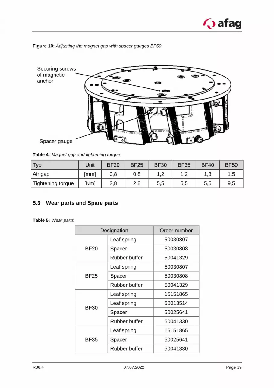
Figure 10: Adjusting the magnet gap with spacer gauges BF50
Table 4: Magnet gap and tightening torque
Typ Unit BF20 BF25 BF30 BF35 BF40 BF50
Air gap [mm] 0,8 0,8 1,2 1,2 1,3 1,5
Tightening torque [Nm] 2,8 2,8 5,5 5,5 5,5 9,5
5.3 Wear parts and Spare parts
Table 5: Wear parts
Designation Order number
BF20
Leaf spring 50030807
Spacer 50030808
Rubber buffer 50041329
BF25
Leaf spring 50030807
Spacer 50030808
Rubber buffer 50041329
BF30
Leaf spring 15151865
Leaf spring 50013514
Spacer 50025641
Rubber buffer 50041330
BF35
Leaf spring 15151865
Spacer 50025641
Rubber buffer 50041330
Spacer gauge
Securing screws of magnetic anchor
Page 20 07.07.2022 R06.4
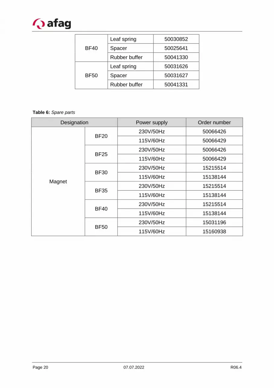
BF40
Leaf spring 50030852
Spacer 50025641
Rubber buffer 50041330
BF50
Leaf spring 50031626
Spacer 50031627
Rubber buffer 50041331
Table 6: Spare parts
Designation Power supply Order number
Magnet
BF20 230V/50Hz 50066426
115V/60Hz 50066429
BF25 230V/50Hz 50066426
115V/60Hz 50066429
BF30 230V/50Hz 15215514
115V/60Hz 15138144
BF35 230V/50Hz 15215514
115V/60Hz 15138144
BF40 230V/50Hz 15215514
115V/60Hz 15138144
BF50 230V/50Hz 15031196
115V/60Hz 15160938
R06.4 07.07.2022 Page 21
6 Accessories
6.1 Adjusting tools
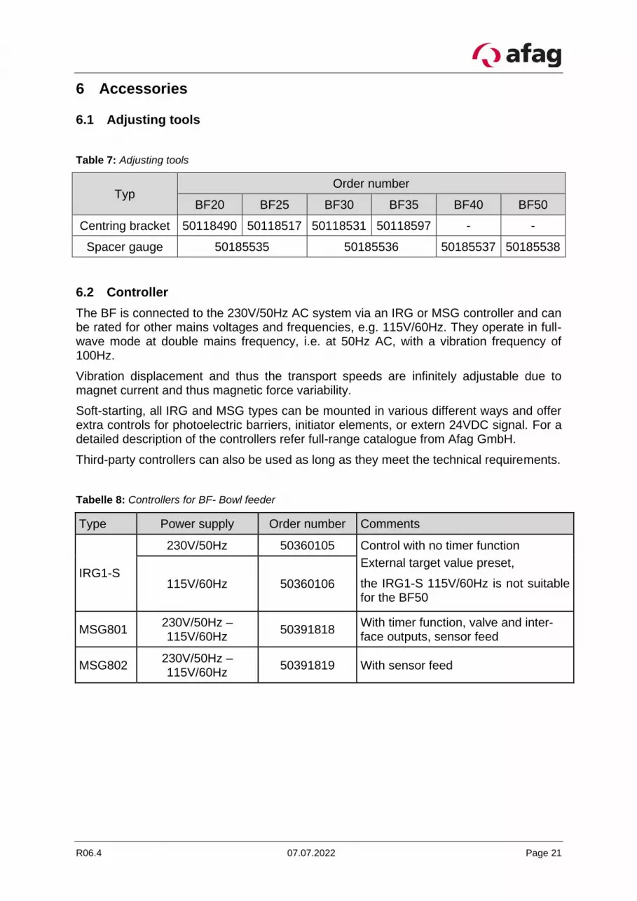
Table 7: Adjusting tools
Typ Order number
BF20 BF25 BF30 BF35 BF40 BF50
Centring bracket 50118490 50118517 50118531 50118597 - -
Spacer gauge 50185535 50185536 50185537 50185538
6.2 Controller
The BF is connected to the 230V/50Hz AC system via an IRG or MSG controller and can be rated for other mains voltages and frequencies, e.g. 115V/60Hz. They operate in full-wave mode at double mains frequency, i.e. at 50Hz AC, with a vibration frequency of 100Hz.
Vibration displacement and thus the transport speeds are infinitely adjustable due to magnet current and thus magnetic force variability.
Soft-starting, all IRG and MSG types can be mounted in various different ways and offer extra controls for photoelectric barriers, initiator elements, or extern 24VDC signal. For a detailed description of the controllers refer full-range catalogue from Afag GmbH.
Third-party controllers can also be used as long as they meet the technical requirements.
Tabelle 8: Controllers for BF- Bowl feeder
Type Power supply Order number Comments
IRG1-S
230V/50Hz 50360105 Control with no timer function
External target value preset,
the IRG1-S 115V/60Hz is not suitable for the BF50
115V/60Hz 50360106
MSG801 230V/50Hz – 115V/60Hz
50391818 With timer function, valve and inter-face outputs, sensor feed
MSG802 230V/50Hz – 115V/60Hz
50391819 With sensor feed
Page 22 07.07.2022 R06.4
6.3 Address for orders
Germany:
Afag GmbH
Wernher-von-Braun-Straße 1
D – 92224 Amberg
Tel.: ++49 (0) 96 21 / 65 0 27-0
Fax: ++49 (0) 96 21 / 65 0 27-490
Sales
www.afag.com
Switzerland:
Afag Automation AG
Luzernstrasse 32
CH – 6144 Zell
Tel.: ++41 (0) 62 / 959 86 86
Fax: ++41 (0) 62 / 959 87 87
7 Disposal
BF feeders that are no longer in use should not be disposed of as complete units but dismantled into separate materials and recycled. Non-recyclable components must be disposed of correctly.


