
nline at www.sciencedirect.com
i n t e rn a t i o n a l j o u r n a l o f r e f r i g e r a t i o n 5 6 ( 2 0 1 5 ) 3 7e4 2
Available o
www. i ifi i r .org
ScienceDirect
journal homepage: www.elsevier .com/locate / i j refr ig
Mechanism of spillage and excessive boiling ofwater during vacuum cooling
Xiao-yan Song, Bao-lin Liu*, Ganesh K. Jaganathan, Lan Chen
Institute of Cryobiology and Food Freezing, University of Shanghai for Science and Technology, 516 Jungong Road,
Shanghai 200093, PR China
a r t i c l e i n f o
Article history:
Received 19 January 2015
Received in revised form
10 March 2015
Accepted 12 April 2015
Available online 20 April 2015
Keywords:
Boiling
Bullet bubble
Spillage
Vacuum cooling
Volumetric displacement
* Corresponding author.E-mail address: [email protected] (B.-l. Liu)
http://dx.doi.org/10.1016/j.ijrefrig.2015.04.0090140-7007/© 2015 Elsevier Ltd and IIR. All rig
a b s t r a c t
Immersion vacuum cooling is a novel method for cooling meat products. This method has
notable advantages including lower water loss rate of products during the cooling process.
However, excessive solution boiling and spillage during immersion vacuum cooling pro-
cess are considered as the serious problems limiting its wide-spread application. In this
study, the mechanism of water boiling and spillage during vacuum cooling was studied by
capturing the images of boiling phenomena with a high speed camera. Results show that
the growth of bullet bubble is a major reason for more than 42% of water loss during
boiling, because the diameter of a bullet bubble can increase to the diameter value of the
test tube in 0.36 s. Our results also show that using moderate volumetric displacement of
vacuum pump (for instance 0.0012 m3 s�1 in this paper) and controlling the chamber
pressure in the range of 10e2 kPa can weaken the intensity of boiling and spillage of water.
These results are discussed in the context of 'classical pool boiling' theory.
© 2015 Elsevier Ltd and IIR. All rights reserved.
M�ecanisme de d�eversement et d'�ebullition excessive de l'eaudurant le refroidissement sous vide
Mots cl�es : Ebullition ; Bulle en balle ; D�eversement ; Refroidissement sous vide ; D�eplacement volum�etrique
1. Introduction
Vacuum cooling is widely used for cooling food products with
a high water content and large porosities, due to its efficacy in
losing water from both within and outside the products
.
hts reserved.
(Augusto et al., 2012; Cepeda et al., 2013; Ozturk and Ozturk,
2009; Rinaldi et al., 2014). The increasing use of this tech-
nique in storing various agricultural, horticultural and ready-
to-eat products such as fruits (He et al., 2013), bakery products,
celery, bamboo shoots (Cheng, 2006), cabbage (Cheng and
Hsueh, 2007), lettuce (Ozturk and Ozturk, 2009), mushrooms
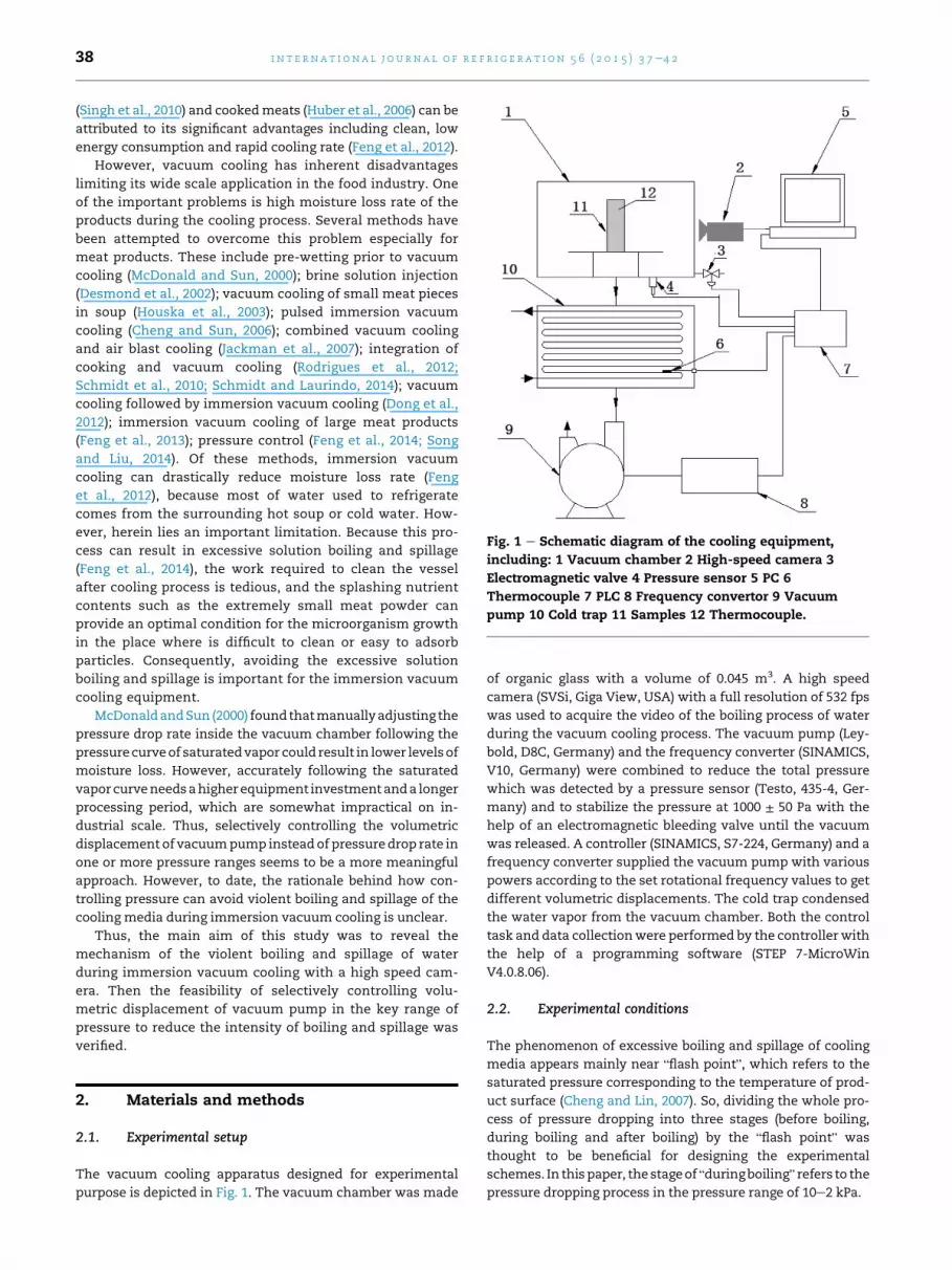
Fig. 1 e Schematic diagram of the cooling equipment,
including: 1 Vacuum chamber 2 High-speed camera 3
Electromagnetic valve 4 Pressure sensor 5 PC 6
Thermocouple 7 PLC 8 Frequency convertor 9 Vacuum
pump 10 Cold trap 11 Samples 12 Thermocouple.
i n t e r n a t i o n a l j o u r n a l o f r e f r i g e r a t i o n 5 6 ( 2 0 1 5 ) 3 7e4 238
(Singh et al., 2010) and cookedmeats (Huber et al., 2006) can be
attributed to its significant advantages including clean, low
energy consumption and rapid cooling rate (Feng et al., 2012).
However, vacuum cooling has inherent disadvantages
limiting its wide scale application in the food industry. One
of the important problems is high moisture loss rate of the
products during the cooling process. Several methods have
been attempted to overcome this problem especially for
meat products. These include pre-wetting prior to vacuum
cooling (McDonald and Sun, 2000); brine solution injection
(Desmond et al., 2002); vacuum cooling of small meat pieces
in soup (Houska et al., 2003); pulsed immersion vacuum
cooling (Cheng and Sun, 2006); combined vacuum cooling
and air blast cooling (Jackman et al., 2007); integration of
cooking and vacuum cooling (Rodrigues et al., 2012;
Schmidt et al., 2010; Schmidt and Laurindo, 2014); vacuum
cooling followed by immersion vacuum cooling (Dong et al.,
2012); immersion vacuum cooling of large meat products
(Feng et al., 2013); pressure control (Feng et al., 2014; Song
and Liu, 2014). Of these methods, immersion vacuum
cooling can drastically reduce moisture loss rate (Feng
et al., 2012), because most of water used to refrigerate
comes from the surrounding hot soup or cold water. How-
ever, herein lies an important limitation. Because this pro-
cess can result in excessive solution boiling and spillage
(Feng et al., 2014), the work required to clean the vessel
after cooling process is tedious, and the splashing nutrient
contents such as the extremely small meat powder can
provide an optimal condition for the microorganism growth
in the place where is difficult to clean or easy to adsorb
particles. Consequently, avoiding the excessive solution
boiling and spillage is important for the immersion vacuum
cooling equipment.
McDonaldandSun (2000) foundthatmanuallyadjusting the
pressure drop rate inside the vacuum chamber following the
pressurecurveof saturatedvapor could result in lower levels of
moisture loss. However, accurately following the saturated
vaporcurveneedsahigherequipment investmentanda longer
processing period, which are somewhat impractical on in-
dustrial scale. Thus, selectively controlling the volumetric
displacement of vacuumpump insteadof pressuredrop rate in
one or more pressure ranges seems to be a more meaningful
approach. However, to date, the rationale behind how con-
trolling pressure can avoid violent boiling and spillage of the
cooling media during immersion vacuum cooling is unclear.
Thus, the main aim of this study was to reveal the
mechanism of the violent boiling and spillage of water
during immersion vacuum cooling with a high speed cam-
era. Then the feasibility of selectively controlling volu-
metric displacement of vacuum pump in the key range of
pressure to reduce the intensity of boiling and spillage was
verified.
2. Materials and methods
2.1. Experimental setup
The vacuum cooling apparatus designed for experimental
purpose is depicted in Fig. 1. The vacuum chamber was made
of organic glass with a volume of 0.045 m3. A high speed
camera (SVSi, Giga View, USA) with a full resolution of 532 fps
was used to acquire the video of the boiling process of water
during the vacuum cooling process. The vacuum pump (Ley-
bold, D8C, Germany) and the frequency converter (SINAMICS,
V10, Germany) were combined to reduce the total pressure
which was detected by a pressure sensor (Testo, 435-4, Ger-
many) and to stabilize the pressure at 1000 ± 50 Pa with the
help of an electromagnetic bleeding valve until the vacuum
was released. A controller (SINAMICS, S7-224, Germany) and a
frequency converter supplied the vacuum pump with various
powers according to the set rotational frequency values to get
different volumetric displacements. The cold trap condensed
the water vapor from the vacuum chamber. Both the control
task and data collectionwere performed by the controller with
the help of a programming software (STEP 7-MicroWin
V4.0.8.06).
2.2. Experimental conditions
The phenomenon of excessive boiling and spillage of cooling
media appears mainly near “flash point”, which refers to the
saturated pressure corresponding to the temperature of prod-
uct surface (Cheng and Lin, 2007). So, dividing the whole pro-
cess of pressure dropping into three stages (before boiling,
during boiling and after boiling) by the “flash point” was
thought to be beneficial for designing the experimental
schemes. In thispaper, thestageof “duringboiling” refers to the
pressure dropping process in the pressure range of 10e2 kPa.
i n t e rn a t i o n a l j o u r n a l o f r e f r i g e r a t i o n 5 6 ( 2 0 1 5 ) 3 7e4 2 39
In our experiment, there were four schemes. They were
performed as follows: (a) seven test tubes containing water
were placed inside the vacuum chamber. Water used in the
experiment was first boiled and allowed to cool to 32 ± 0.5 �C.Each test tube was filled with 100 mL volume of water; (b) into
one of the test tubes, a thermocouple was embedded at 1 cm
below the water surface to measure the temperature change
during the cooling process; (c) the chamber door was closed
tightly; (d) images were taken at a frame rate of 100 frames s�1
by the high speed video camera during the whole vacuum
cooling process; (e) when the cold trap was cooled to - 6 �C,both the vacuum pump and frequency convertor were
switched on, and the pressure of vacuum chamber was
reduced to 1000 Pa and maintained at this range until the
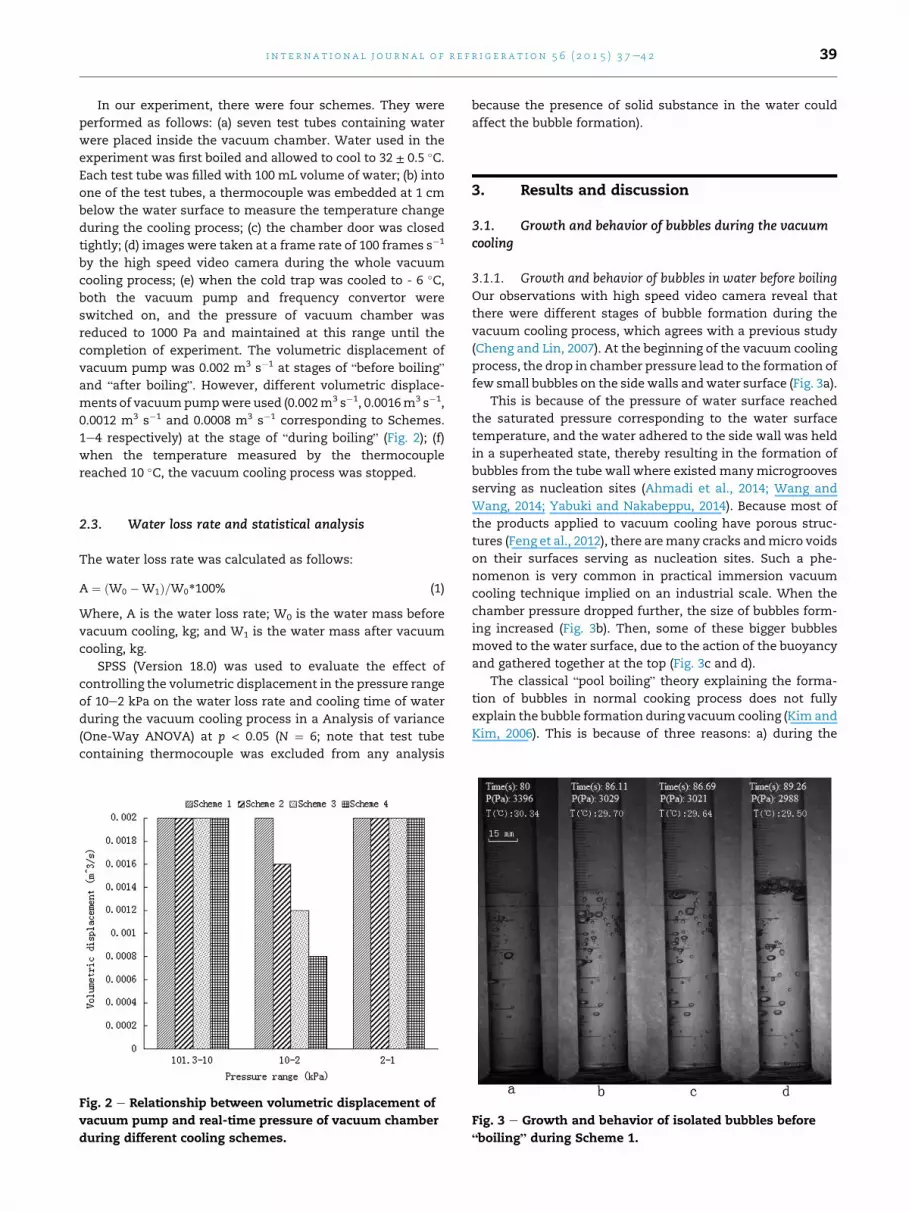
completion of experiment. The volumetric displacement of
vacuum pump was 0.002 m3 s�1 at stages of “before boiling”
and “after boiling”. However, different volumetric displace-
ments of vacuumpumpwere used (0.002m3 s�1, 0.0016m3 s�1,
0.0012 m3 s�1 and 0.0008 m3 s�1 corresponding to Schemes.
1e4 respectively) at the stage of “during boiling” (Fig. 2); (f)
when the temperature measured by the thermocouple
reached 10 �C, the vacuum cooling process was stopped.
2.3. Water loss rate and statistical analysis
The water loss rate was calculated as follows:
A ¼ ðW0 �W1Þ=W0*100% (1)
Where, A is the water loss rate; W0 is the water mass before
vacuum cooling, kg; and W1 is the water mass after vacuum
cooling, kg.
SPSS (Version 18.0) was used to evaluate the effect of
controlling the volumetric displacement in the pressure range
of 10e2 kPa on the water loss rate and cooling time of water
during the vacuum cooling process in a Analysis of variance
(One-Way ANOVA) at p < 0.05 (N ¼ 6; note that test tube
containing thermocouple was excluded from any analysis
Fig. 2 e Relationship between volumetric displacement of
vacuum pump and real-time pressure of vacuum chamber
during different cooling schemes.
because the presence of solid substance in the water could
affect the bubble formation).
3. Results and discussion
3.1. Growth and behavior of bubbles during the vacuumcooling
3.1.1. Growth and behavior of bubbles in water before boilingOur observations with high speed video camera reveal that
there were different stages of bubble formation during the
vacuum cooling process, which agrees with a previous study
(Cheng and Lin, 2007). At the beginning of the vacuum cooling
process, the drop in chamber pressure lead to the formation of
few small bubbles on the sidewalls andwater surface (Fig. 3a).
This is because of the pressure of water surface reached
the saturated pressure corresponding to the water surface
temperature, and the water adhered to the side wall was held
in a superheated state, thereby resulting in the formation of
bubbles from the tube wall where existed manymicrogrooves
serving as nucleation sites (Ahmadi et al., 2014; Wang and
Wang, 2014; Yabuki and Nakabeppu, 2014). Because most of
the products applied to vacuum cooling have porous struc-
tures (Feng et al., 2012), there aremany cracks andmicro voids
on their surfaces serving as nucleation sites. Such a phe-
nomenon is very common in practical immersion vacuum
cooling technique implied on an industrial scale. When the
chamber pressure dropped further, the size of bubbles form-
ing increased (Fig. 3b). Then, some of these bigger bubbles
moved to the water surface, due to the action of the buoyancy
and gathered together at the top (Fig. 3c and d).
The classical “pool boiling” theory explaining the forma-
tion of bubbles in normal cooking process does not fully
explain the bubble formation during vacuum cooling (Kim and
Kim, 2006). This is because of three reasons: a) during the
Fig. 3 e Growth and behavior of isolated bubbles before
“boiling” during Scheme 1.
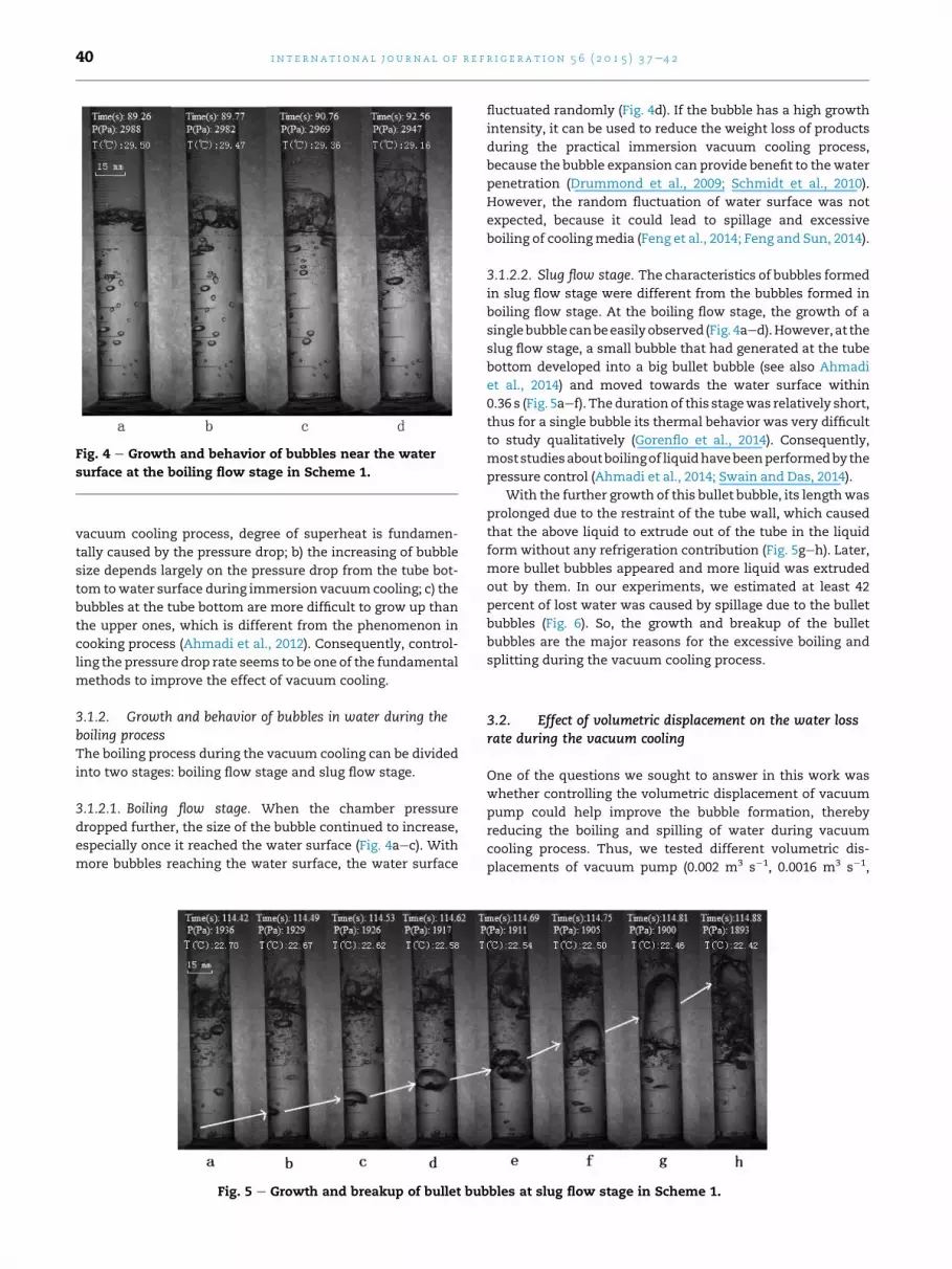
Fig. 4 e Growth and behavior of bubbles near the water
surface at the boiling flow stage in Scheme 1.
i n t e r n a t i o n a l j o u r n a l o f r e f r i g e r a t i o n 5 6 ( 2 0 1 5 ) 3 7e4 240
vacuum cooling process, degree of superheat is fundamen-
tally caused by the pressure drop; b) the increasing of bubble
size depends largely on the pressure drop from the tube bot-
tom towater surface during immersion vacuum cooling; c) the
bubbles at the tube bottom are more difficult to grow up than
the upper ones, which is different from the phenomenon in
cooking process (Ahmadi et al., 2012). Consequently, control-
ling the pressure drop rate seems to be one of the fundamental
methods to improve the effect of vacuum cooling.
3.1.2. Growth and behavior of bubbles in water during theboiling processThe boiling process during the vacuum cooling can be divided
into two stages: boiling flow stage and slug flow stage.
3.1.2.1. Boiling flow stage. When the chamber pressure
dropped further, the size of the bubble continued to increase,
especially once it reached the water surface (Fig. 4aec). With
more bubbles reaching the water surface, the water surface
Fig. 5 e Growth and breakup of bullet bub
fluctuated randomly (Fig. 4d). If the bubble has a high growth
intensity, it can be used to reduce the weight loss of products
during the practical immersion vacuum cooling process,
because the bubble expansion can provide benefit to thewater
penetration (Drummond et al., 2009; Schmidt et al., 2010).
However, the random fluctuation of water surface was not
expected, because it could lead to spillage and excessive
boiling of coolingmedia (Feng et al., 2014; Feng and Sun, 2014).
3.1.2.2. Slug flow stage. The characteristics of bubbles formed
in slug flow stage were different from the bubbles formed in
boiling flow stage. At the boiling flow stage, the growth of a
singlebubblecanbeeasilyobserved (Fig. 4aed).However,at the
slug flow stage, a small bubble that had generated at the tube
bottom developed into a big bullet bubble (see also Ahmadi
et al., 2014) and moved towards the water surface within
0.36 s (Fig. 5aef). Thedurationof this stagewas relatively short,
thus for a single bubble its thermal behavior was very difficult
to study qualitatively (Gorenflo et al., 2014). Consequently,
moststudiesaboutboilingof liquidhavebeenperformedby the
pressure control (Ahmadi et al., 2014; Swain and Das, 2014).
With the further growth of this bullet bubble, its lengthwas
prolonged due to the restraint of the tube wall, which caused
that the above liquid to extrude out of the tube in the liquid
form without any refrigeration contribution (Fig. 5geh). Later,
more bullet bubbles appeared and more liquid was extruded
out by them. In our experiments, we estimated at least 42
percent of lost water was caused by spillage due to the bullet
bubbles (Fig. 6). So, the growth and breakup of the bullet
bubbles are the major reasons for the excessive boiling and
splitting during the vacuum cooling process.
3.2. Effect of volumetric displacement on the water lossrate during the vacuum cooling
One of the questions we sought to answer in this work was
whether controlling the volumetric displacement of vacuum
pump could help improve the bubble formation, thereby
reducing the boiling and spilling of water during vacuum
cooling process. Thus, we tested different volumetric dis-
placements of vacuum pump (0.002 m3 s�1, 0.0016 m3 s�1,
bles at slug flow stage in Scheme 1.
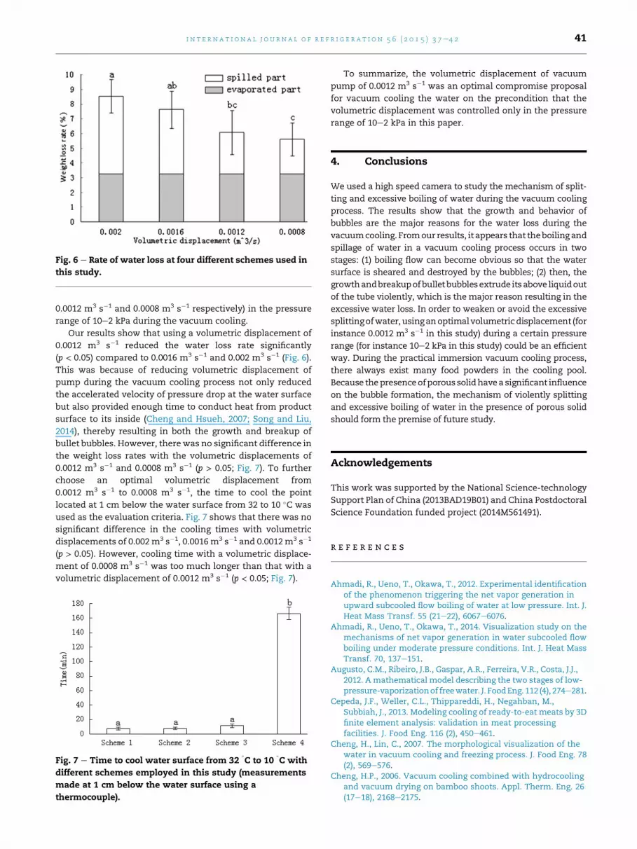
Fig. 6 e Rate of water loss at four different schemes used in
this study.
i n t e rn a t i o n a l j o u r n a l o f r e f r i g e r a t i o n 5 6 ( 2 0 1 5 ) 3 7e4 2 41
0.0012 m3 s�1 and 0.0008 m3 s�1 respectively) in the pressure
range of 10e2 kPa during the vacuum cooling.
Our results show that using a volumetric displacement of
0.0012 m3 s�1 reduced the water loss rate significantly
(p < 0.05) compared to 0.0016 m3 s�1 and 0.002 m3 s�1 (Fig. 6).
This was because of reducing volumetric displacement of
pump during the vacuum cooling process not only reduced
the accelerated velocity of pressure drop at the water surface
but also provided enough time to conduct heat from product
surface to its inside (Cheng and Hsueh, 2007; Song and Liu,
2014), thereby resulting in both the growth and breakup of
bullet bubbles. However, therewas no significant difference in
the weight loss rates with the volumetric displacements of
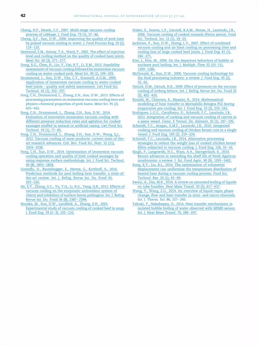
0.0012 m3 s�1 and 0.0008 m3 s�1 (p > 0.05; Fig. 7). To further
choose an optimal volumetric displacement from
0.0012 m3 s�1 to 0.0008 m3 s�1, the time to cool the point
located at 1 cm below the water surface from 32 to 10 �C was
used as the evaluation criteria. Fig. 7 shows that there was no
significant difference in the cooling times with volumetric
displacements of 0.002m3 s�1, 0.0016m3 s�1 and 0.0012m3 s�1
(p > 0.05). However, cooling time with a volumetric displace-
ment of 0.0008 m3 s�1 was too much longer than that with a
volumetric displacement of 0.0012 m3 s�1 (p < 0.05; Fig. 7).
Fig. 7 e Time to cool water surface from 32�C to 10
�C with
different schemes employed in this study (measurements
made at 1 cm below the water surface using a
thermocouple).
To summarize, the volumetric displacement of vacuum
pump of 0.0012 m3 s�1 was an optimal compromise proposal
for vacuum cooling the water on the precondition that the
volumetric displacement was controlled only in the pressure
range of 10e2 kPa in this paper.
4. Conclusions
We used a high speed camera to study the mechanism of split-
ting and excessive boiling of water during the vacuum cooling
process. The results show that the growth and behavior of
bubbles are the major reasons for the water loss during the
vacuumcooling. Fromour results, it appears that theboiling and
spillage of water in a vacuum cooling process occurs in two
stages: (1) boiling flow can become obvious so that the water
surface is sheared and destroyed by the bubbles; (2) then, the
growthandbreakupofbulletbubblesextrude itsabove liquidout
of the tube violently, which is the major reason resulting in the
excessive water loss. In order to weaken or avoid the excessive
splittingofwater,usinganoptimalvolumetricdisplacement (for
instance 0.0012 m3 s�1 in this study) during a certain pressure
range (for instance 10e2 kPa in this study) could be an efficient
way. During the practical immersion vacuum cooling process,
there always exist many food powders in the cooling pool.
Because thepresenceofporoussolidhavea significant influence
on the bubble formation, the mechanism of violently splitting
and excessive boiling of water in the presence of porous solid
should form the premise of future study.
Acknowledgements
This work was supported by the National Science-technology
Support Plan of China (2013BAD19B01) and China Postdoctoral
Science Foundation funded project (2014M561491).
r e f e r e n c e s
Ahmadi, R., Ueno, T., Okawa, T., 2012. Experimental identificationof the phenomenon triggering the net vapor generation inupward subcooled flow boiling of water at low pressure. Int. J.Heat Mass Transf. 55 (21e22), 6067e6076.
Ahmadi, R., Ueno, T., Okawa, T., 2014. Visualization study on themechanisms of net vapor generation in water subcooled flowboiling under moderate pressure conditions. Int. J. Heat MassTransf. 70, 137e151.
Augusto, C.M., Ribeiro, J.B., Gaspar, A.R., Ferreira, V.R., Costa, J.J.,2012. A mathematical model describing the two stages of low-pressure-vaporizationof freewater. J. FoodEng. 112 (4), 274e281.
Cepeda, J.F., Weller, C.L., Thippareddi, H., Negahban, M.,Subbiah, J., 2013. Modeling cooling of ready-to-eat meats by 3Dfinite element analysis: validation in meat processingfacilities. J. Food Eng. 116 (2), 450e461.
Cheng, H., Lin, C., 2007. The morphological visualization of thewater in vacuum cooling and freezing process. J. Food Eng. 78(2), 569e576.
Cheng, H.P., 2006. Vacuum cooling combined with hydrocoolingand vacuum drying on bamboo shoots. Appl. Therm. Eng. 26(17e18), 2168e2175.
i n t e r n a t i o n a l j o u r n a l o f r e f r i g e r a t i o n 5 6 ( 2 0 1 5 ) 3 7e4 242
Cheng, H.P., Hsueh, C.F., 2007. Multi-stage vacuum coolingprocess of cabbage. J. Food Eng. 79 (1), 37e46.
Cheng, Q.F., Sun, D.W., 2006. Improving the quality of pork hamby pulsed vacuum cooling in water. J. Food Process Eng. 29 (2),119e133.
Desmond, E.M., Kenny, T.A., Ward, P., 2002. The effect of injectionlevel and cooling method on the quality of cooked ham joints.Meat Sci. 60 (3), 271e277.
Dong, X.G., Chen, H., Liu, Y., Dai, R.T., Li, X.M., 2012. Feasibilityassessment of vacuum cooling followed by immersion vacuumcooling on water-cooked pork. Meat Sci. 90 (1), 199e203.
Drummond, L., Sun, D.W., Vila, C.T., Scannell, A.G.M., 2009.Application of immersion vacuum cooling to water-cookedbeef joints - quality and safety assessment. Lwt Food Sci.Technol. 42 (1), 332e337.
Feng, C.H., Drummond, L., Zhang, Z.H., Sun, D.W., 2013. Effects ofprocessing parameters on immersion vacuumcooling time andphysico-chemical properties of pork hams. Meat Sci. 95 (2),425e432.
Feng, C.H., Drummond, L., Zhang, Z.H., Sun, D.W., 2014.Evaluation of innovative immersion vacuum cooling withdifferent pressure reduction rates and agitation for cookedsausages stuffed in natural or artificial casing. Lwt Food Sci.Technol. 59 (1), 77e85.
Feng, C.H., Drummond, L., Zhang, Z.H., Sun, D.W., Wang, Q.J.,2012. Vacuum cooling of meat products: current state-of-the-art research advances. Crit. Rev. Food Sci. Nutr. 52 (11),1024e1038.
Feng, C.H., Sun, D.W., 2014. Optimisation of immersion vacuumcooling operation and quality of Irish cooked sausages byusing response surface methodology. Int. J. Food Sci. Technol.49 (8), 1850e1858.
Gorenflo, D., Baumhogger, E., Herres, G., Kotthoff, S., 2014.Prediction methods for pool boiling heat transfer: a state-of-the-art review. Int. J. Refrig. Revue Int. Du. Froid 43,203e226.
He, S.Y., Zhang, G.C., Yu, Y.Q., Li, R.G., Yang, Q.R., 2013. Effects ofvacuum cooling on the enzymatic antioxidant system ofcherry and inhibition of surface-borne pathogens. Int. J. Refrig.Revue Int. Du. Froid 36 (8), 2387e2394.
Houska, M., Sun, D.W., Landfeld, A., Zhang, Z.H., 2003.Experimental study of vacuum cooling of cooked beef in soup.J. Food Eng. 59 (2e3), 105e110.
Huber, E., Soares, L.P., Carciofi, B.A.M., Hense, H., Laurindo, J.B.,2006. Vacuum cooling of cooked mussels (Perna perna). FoodSci. Technol. Int. 12 (1), 19e25.
Jackman, P., Sun, D.W., Zheng, L.Y., 2007. Effect of combinedvacuum cooling and air blast cooling on processing time andcooling loss of large cooked beef joints. J. Food Eng. 81 (1),266e271.
Kim, J., Kim, M., 2006. On the departure behaviors of bubble atnucleate pool boiling. Int. J. Multiph. Flow 32 (10e11),1269e1286.
McDonald, K., Sun, D.W., 2000. Vacuum cooling technology forthe food processing industry: a review. J. Food Eng. 45 (2),55e65.
Ozturk, H.M., Ozturk, H.K., 2009. Effect of pressure on the vacuumcooling of iceberg lettuce. Int. J. Refrig. Revue Int. Du. Froid 32(3), 402e410.
Rinaldi, M., Chiavaro, E., Massini, R., 2014. Mathematicalmodelling of heat transfer in Mortadella Bologna PGI duringevaporative pre-cooling. Int. J. Food Eng. 10 (2), 233e241.
Rodrigues, L.G.G., Cavalheiro, D., Schmidt, F.C., Laurindo, J.B.,2012. Integration of cooking and vacuum cooling of carrots ina same vessel. Cienc. E Tecnol. De. Aliment. 32 (1), 187e195.
Schmidt, F.C., Aragao, G.M.F., Laurindo, J.B., 2010. Integratedcooking and vacuum cooling of chicken breast cuts in a singlevessel. J. Food Eng. 100 (2), 219e224.
Schmidt, F.C., Laurindo, J.B., 2014. Alternative processingstrategies to reduce the weight loss of cooked chicken breastfillets subjected to vacuum cooling. J. Food Eng. 128, 10e16.
Singh, P., Langowski, H.C., Wani, A.A., Saengerlaub, S., 2010.Recent advances in extending the shelf life of fresh Agaricusmushrooms: a review. J. Sci. Food Agric. 90 (9), 1393e1402.
Song, X.Y., Liu, B.L., 2014. The optimization of volumetricdisplacement can uniformize the temperature distribution ofheated ham during a vacuum cooling process. Food Sci.Technol. Res. 20 (1), 43e49.
Swain, A., Das, M.K., 2014. A review on saturated boiling of liquidson tube bundles. Heat Mass Transf. 50 (5), 617e637.
Wang, Y., Wang, Z.G., 2014. An overview of liquid-vapor phasechange, flow and heat transfer in mini- and micro-channels.Int. J. Therm. Sci. 86, 227e245.
Yabuki, T., Nakabeppu, O., 2014. Heat transfer mechanisms inisolated bubble boiling of water observed with MEMS sensor.Int. J. Heat Mass Transf. 76, 286e297.


