THE JOURNAL OF THE AMERICAN CERAMIC SOCIETY Volume 27 May 1,1944 Number 5 VISCOSITY OF RECENT CONTAINER GLASS* BY HOWARD A. ROBINSON AND CHARLES A. PETERSON ABSTRACT A high-temperature, concentric cylinder viscometer has been constructed and cali- brated. The calibration checks within 1% that obtained by Lillie for a similar appara- tus and provides further evidence of the high degree of reliability of this type of meas- urement. The contention of Washburn and Shelton that the calibration in such instru- ments is a function of the viscosity is shown to be false. Because four independent investigations have been unable to check this contention, it may now be regarded as spurious. A medium temperature-range fiber viscometer for measuring the viscosity of glass in the annealing range has also been constructed. It is shown that the Fulcher equation, log q = -A + __ , fits the data obtained on the two instruments to within 0.5% for commercial soda-lime glasses. Complete viscosity data as a function of tem- perature are given for sixteen commercialcontainer glasses. and the analyses are also in- cluded. These glasses show a wide range of viscosity. T - To 1. Introduction Experimental work in many laboratories during the past twenty years has shown that the viscosity of glass depends markedly on its chemical composition. Pub- lished data on glass viscosity, however, have not usually included accurate analyses, particularly when commercial glasses have been measured. Check tests among various laboratories have been sporadic and not infrequently carried out on glasses of “similar composi- tion” rather than of identical composition. It would seem, therefore, to be of value to record in one place glass viscosities obtained over a period of the last three years and to describe the apparatus which has been built to measure them. Originally i t was planned t o include several additional glasses in this list, but, in view of the present press of defense work, it has been necessary to defer this project until after the war. It is impossible to use a single piece of equipment to measure the viscosity of glass over the entire range of technical interest because apparatus which is capable of accurate measurement at 100 poiset can scarcely be suitable for measuring viscosity at loi6 poise. Three different pieces of apparatus actually have been used to cover this range. The first of these is a concentric * Presented at the Forty-Fifth Annual Meeting, The American Ceramic Society, Pittsburgh, Pa., April 21, 1943 (Glass Division). Received September 2,1943. t The singular form of “poise” is being used through this paper at the request of the author. cylinder apparatus similar to that described by Lillie. This equipment may be used to measure viscosities be- tween 100 and 3 million poise. A fiber viscometer similar to those described by Lillie,* N ~ r t o n , ~ and Tay- lor‘ has been built for the region between 1O’O and loig poise. In the region between lo6 and loLo poise, the empirical softening-point furnace can be used to meas- ure that temperature at which viscosity is equal to 1.5 X lo7 poise. These three pieces of equipment give viscosity values which lie on a single smooth curve. 1 (a) H. R. Lillie, “Measurement of Absolute Viscosity by Use of Concentric Cylinders.” Jour. Amer. Ceram. Soc., (b) H. R. Lillie, “Viscosity Measurements in Glass,” (c) H. R. Lillie, Margules Method of Measuring Vis- cosities Modified to Give Absolute Values.” Phvs. Rev.. I2 [Sl 505-15 (1929). ibid., 12 [8] 516-29 (A929). , . 36, 347 (1930). (d) H. R. Lila?, “High-Temperature Viscosities of Soda-Silica Glasses, lour. Amer. Ceram. SOC., 22 [ll] * H. R. Lillie, “Viscosity of Glass Between Strain Point and Melting Temp:;ature,” ibid., 14 [7] 502-11 (1931). a F. H. Norton, Measuring Viscosity of Glass,” Glass Id., 16 [5114344 (1935); Ceram. Abs., ,!4 [7] 160 (1935). 4 (a) Elastic and Vis- cous Properties of Sever;l Soda-Silica Glasses in Annealing Range of Temperature, Jour. Amer. Ceram. SOC., 20 191 N. W. Taylor, E. P. McNamara, and J. Sherman, “Elastico-Viscous Properties of Soda-Lime-Siica Glass at Temperatures near ‘Transformation Point,’ ” Jour. SOC. Glass Tech., 21 [83] 61-81 (1937); Ceram. Abs., 17 [8] 273 (1938). 367-74 (1939). N. W. Taylor and P. S. Dear, 29304 (1937). (b) 129
Transcript
THE JOURNAL OF
THE AMERICAN CERAMIC S O C I E T Y
Volume 27 May 1,1944 Number 5
VISCOSITY OF RECENT C O N T A I N E R GLASS* BY HOWARD A. ROBINSON AND CHARLES A. PETERSON
ABSTRACT A high-temperature, concentric cylinder viscometer has been constructed and cali-
brated. The calibration checks within 1% that obtained by Lillie for a similar appara- tus and provides further evidence of the high degree of reliability of this type of meas- urement. The contention of Washburn and Shelton that the calibration in such instru- ments is a function of the viscosity is shown to be false. Because four independent investigations have been unable to check this contention, it may now be regarded as spurious. A medium temperature-range fiber viscometer for measuring the viscosity of glass in the annealing range has also been constructed. I t is shown that the Fulcher
equation, log q = - A + __ , fits the data obtained on the two instruments to within
0.5% for commercial soda-lime glasses. Complete viscosity data as a function of tem- perature are given for sixteen commercial container glasses. and the analyses are also in- cluded. These glasses show a wide range of viscosity.
T - To
1. Introduction Experimental work in many laboratories during the
past twenty years has shown that the viscosity of glass depends markedly on its chemical composition. Pub- lished data on glass viscosity, however, have not usually included accurate analyses, particularly when commercial glasses have been measured. Check tests among various laboratories have been sporadic and not infrequently carried out on glasses of “similar composi- tion” rather than of identical composition. It would seem, therefore, to be of value to record in one place glass viscosities obtained over a period of the last three years and to describe the apparatus which has been built to measure them. Originally i t was planned t o include several additional glasses in this list, but, in view of the present press of defense work, it has been necessary to defer this project until after the war.
It is impossible to use a single piece of equipment to measure the viscosity of glass over the entire range of technical interest because apparatus which is capable of accurate measurement at 100 poiset can scarcely be suitable for measuring viscosity at loi6 poise. Three different pieces of apparatus actually have been used to cover this range. The first of these is a concentric
* Presented at the Forty-Fifth Annual Meeting, The American Ceramic Society, Pittsburgh, Pa., April 21, 1943 (Glass Division). Received September 2, 1943.
t The singular form of “poise” is being used through this paper at the request of the author.
cylinder apparatus similar to that described by Lillie. This equipment may be used to measure viscosities be- tween 100 and 3 million poise. A fiber viscometer similar to those described by Lillie,* N ~ r t o n , ~ and Tay- lor‘ has been built for the region between 1O’O and loig poise. In the region between lo6 and loLo poise, the empirical softening-point furnace can be used to meas- ure that temperature a t which viscosity is equal to 1.5 X lo7 poise. These three pieces of equipment give viscosity values which lie on a single smooth curve.
1 (a) H. R. Lillie, “Measurement of Absolute Viscosity by Use of Concentric Cylinders.” Jour. Amer. Ceram. Soc.,
(b ) H. R. Lillie, “Viscosity Measurements in Glass,”
(c) H. R. Lillie, Margules Method of Measuring Vis- cosities Modified to Give Absolute Values.” Phvs. Rev..
I2 [Sl 505-15 (1929).
ibid., 12 [8] 516-29 (A929).
, . 36, 347 (1930).
( d ) H. R. Lila?, “High-Temperature Viscosities of Soda-Silica Glasses, lour. Amer. Ceram. SOC., 22 [ll]
* H. R. Lillie, “Viscosity of Glass Between Strain Point and Melting Temp:;ature,” ibid., 14 [7] 502-11 (1931).
a F. H. Norton, Measuring Viscosity of Glass,” Glass Id., 16 [51 14344 (1935); Ceram. Abs., ,!4 [7] 160 (1935).
4 (a) Elastic and Vis- cous Properties of Sever;l Soda-Silica Glasses in Annealing Range of Temperature, Jour. Amer. Ceram. SOC., 20 191
N. W. Taylor, E. P. McNamara, and J. Sherman, “Elastico-Viscous Properties of Soda-Lime-Siica Glass at Temperatures near ‘Transformation Point,’ ” Jour. SOC. Glass Tech., 21 [83] 61-81 (1937); Ceram. Abs., 17 [8] 273 (1938).
367-74 (1939).
N. W. Taylor and P. S. Dear,
29304 (1937). (b )
129
130 Journal of The American Ceramic Society-Robinson and Peterson
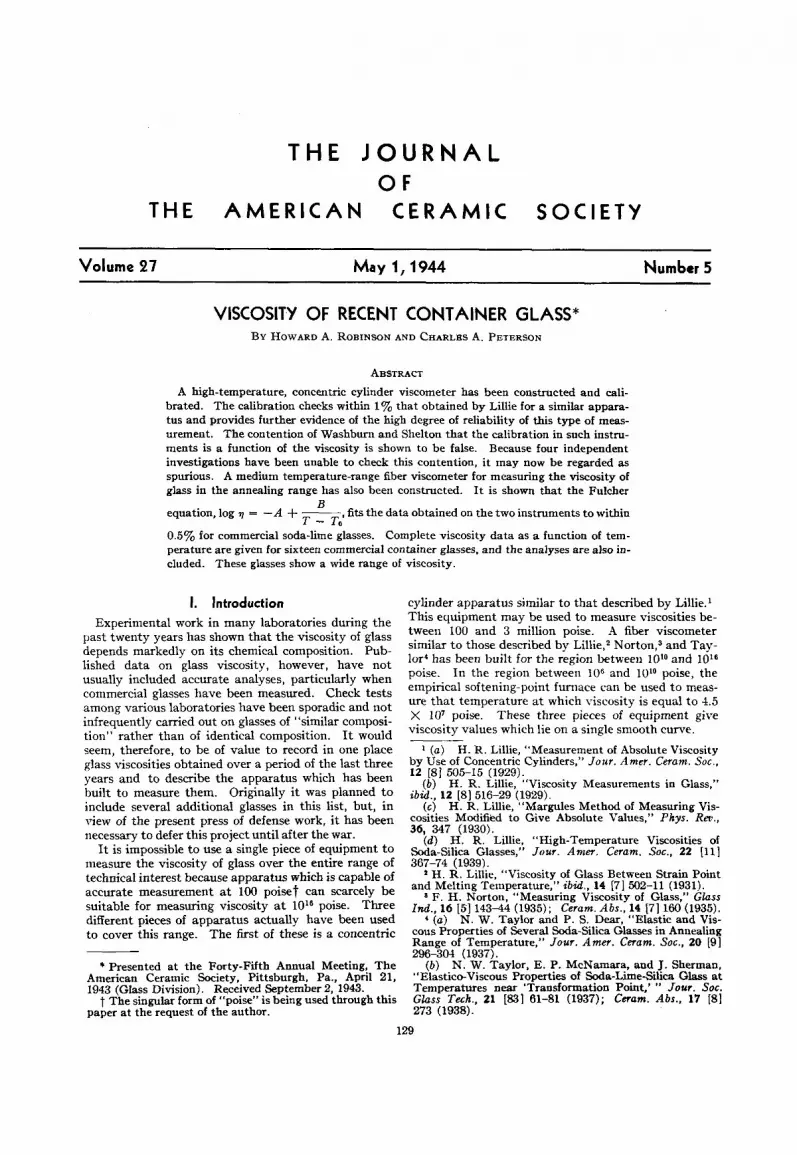
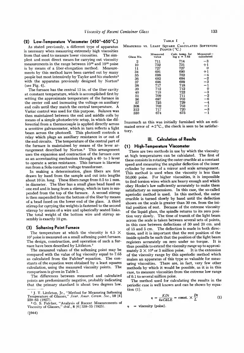
FIG. 1.-High-temperature viscometer in early stages before circular scale was added.
II. Methods (1) High-TemperatureViscometer(800”-1 500°C.)
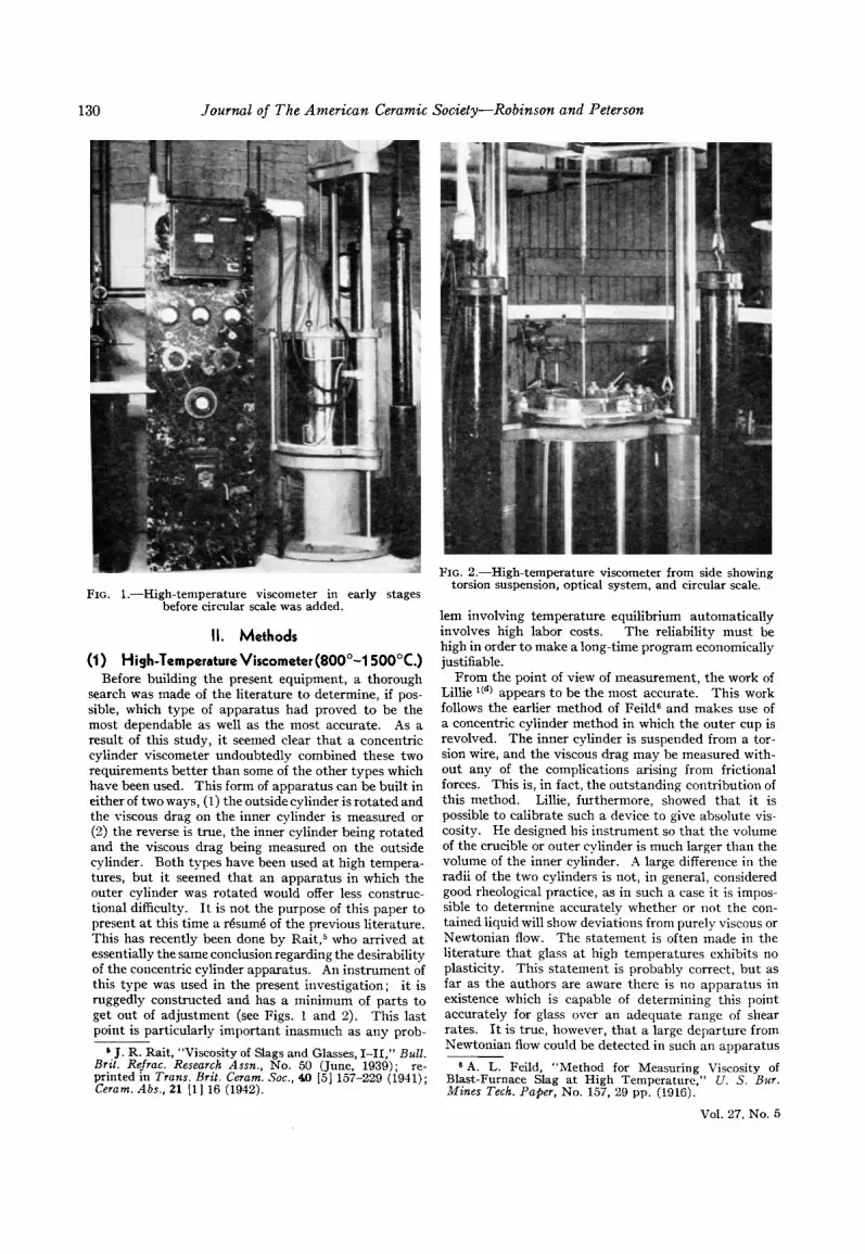
Before building the present equipment, a thorough search was made of the literature to determine, if pos- sible, which type of apparatus had proved to be the most dependable as well as the most accurate. As a result of this study, it seemed clear that a concentric cylinder viscometer undoubtedly combined these two requirements better than some of the other types which have been used. This form of apparatus can be built in either of two ways, (1) the outside cylinder is rotated and the viscous drag on the inner cylinder is measured or (2) the reverse is true, the inner cylinder being rotated and the viscous drag being measured on the outside cylinder. Both types have been used a t high tempera- tures, but it seemed that an apparatus in which the outer cylinder was rotated would offer less construc- tional difficulty. I t is not the purpose of this paper to present a t this time a rBsum6 of the previous literature. This has recently been done by Rait,5 who arrived a t essentially the same conclusion regarding the desirability of the concentric cylinder apparatus. An instrument of this type was used in the present investigation; it is ruggedly constructed and has a minimum of parts to get out of adjustment (see Figs. 1 and 2). This last point is particularly important inasmuch as any prob-
* J. R. Rait, “Viscosity of Slags and Glasses, 1-11,’’ Bull. Brit. Rejrac. Research Assn., No. 50 (June, 1939); re- printed in Trans. Brit. Ceram. SOC., 40 [5] 157-229 (1911); Ceram. Abs.. 21 111 16 (1912).
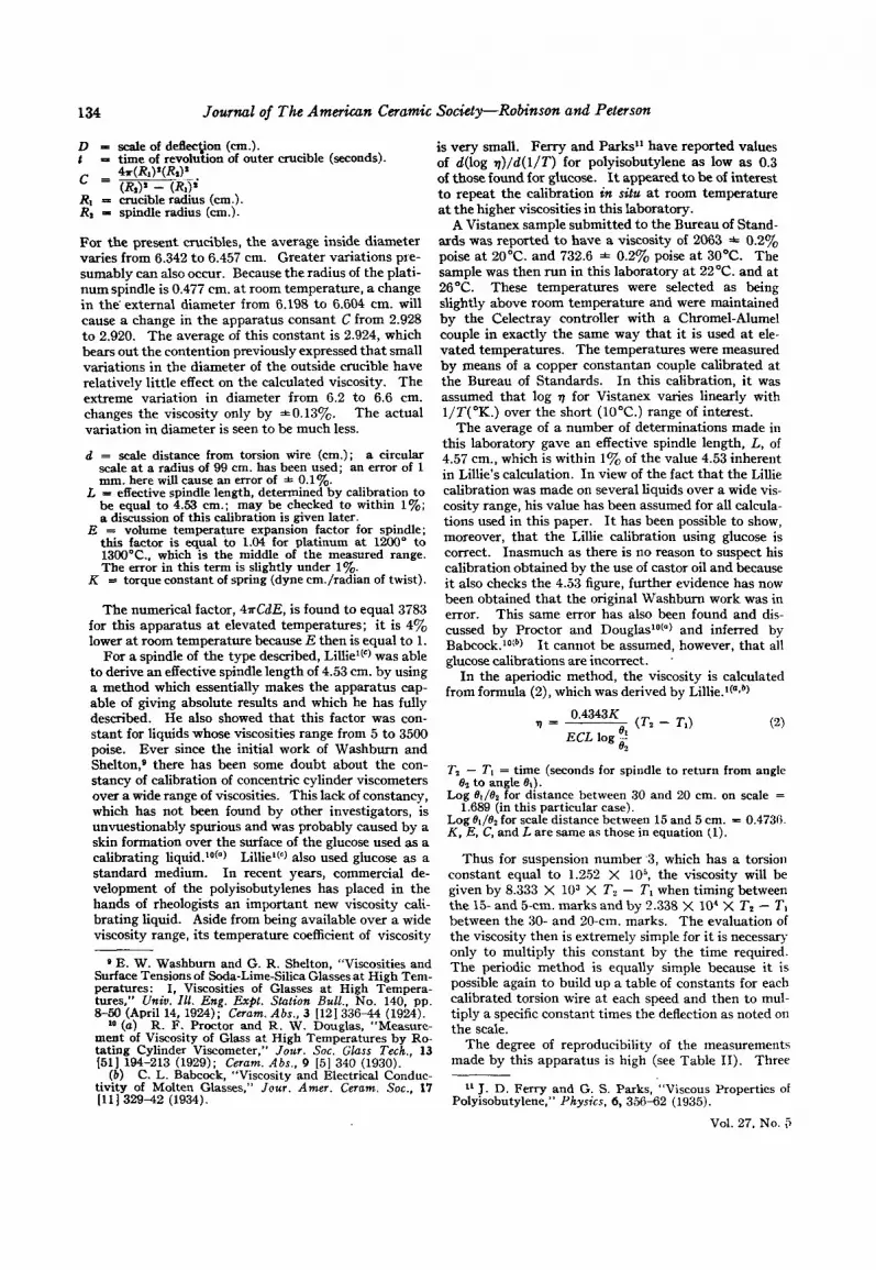
FIG. a.-High-temperature viscometer from side showing torsion suspension, optical system, and circular scale.
lem involving temperature equilibrium automatically involves high labor costs. The reliability must be high in order to make a long-time program economically justifiable.
From the point of view of measurement, the work of Lillie l(d) appears to be the most accurate. This work follows the earlier method of Feild6 and makes use of a concentric cylinder method in which the outer cup is revolved. The inner cylinder is suspended from a tor- sion wire, and the viscous drag may be measured with- out any of the complications arising from frictional forces. This is, in fact, the outstanding contribution of this method. Lillie, furthermore, showed that i t is possible to calibrate such a device to give absolute vis- cosity. He designed his instrument so that the volume of the crucible or outer cylinder is much larger than the volume of the inner cylinder. A large difference in the radii of the two cylinders is not, in general, considered good rheological practice, as in such a case it is impos- sible to determine accurately whether or not the con- tained liquid will show deviations from purely viscous or Newtonian flow. The statement is often made in the literature that glass at high temperatures exhibits no plasticity. This statement is probably correct, but as far as the authors are aware there is no apparatus in existence which is capable of determining this point accurately for glass over an adequate range of shear rates. It is true, however, that a large departure from Newtonian flow could be detected in such an apparatus
‘ A . L. Feild, “Method for Measuring Viscosity of Blast-Furnace Slag at High Temperature,” U. S. Bur. Mines Tech. Paper, No. 157, 29 pp. (1916).
Vol. 27. No. 5
Viscosity of Recent Container Glass 131
identical with that of Lillie.l(d) The crucibles are 6.35 cm. in inside diameter and 16.5 cm. high. This height is necessary inasmuch as the crushed sample fills the crucible completelv during loading and melts down to
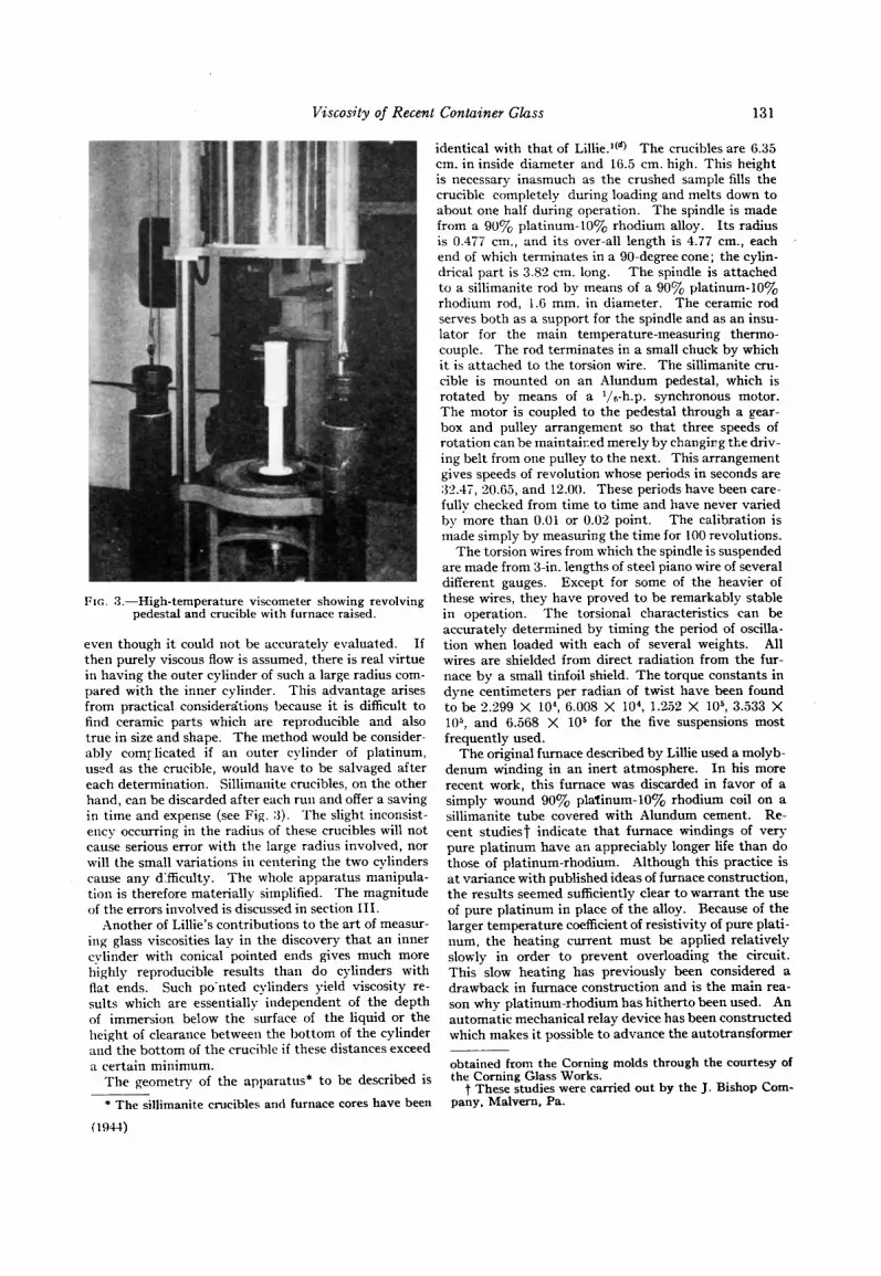
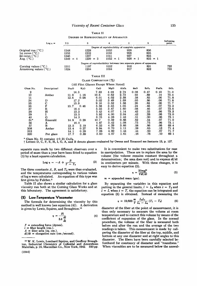
FIG. 3.-High-temperature viscometer showing revolving pedestal and crucible with furnace raised.
even though it could not be accurately evaluated. If then purely viscous flow is assumed, there is real virtue in having the outer cylinder of such a large radius com- pared with the inner cylinder. This advantage arises from practical considerzitions because it is difficult to find ceramic parts which are reproducible and also true in size and shape. The method would be consider- ably comrlicated if an outer cylinder of platinum, used as the crucible, would have to be salvaged after each determination. Sillimanite crucibles, on the other hand, can be discarded after each run and offer a saving in time and expense (see Fig. 3 ) . The slight inconsist- ency occurring in the radius of these crucibles will not cause serious error with the large radius involved, nor will the small variations in centering the two cylinders cause any d’fficulty. The whole apparatus nianipula- tion is therefore materially simplified. The magnitude of the errors involved is discussed in section 111.
Another of Lillie’s contributions to the art of measur- ing glass viscosities lay in the discovery that an inner cylinder with conical pointed ends gives much more highly reproducible results than do cylinders with flat ends. Such po.nted cylinders yield viscosity re- sults which are essentially independent of the depth of immersion below the surface of the liquid or the height of clearance between the bottom of the cylinder and the bottom of the crucible if these distances exceed a certain minimum.
The geometry of the apparatus* to be described is
* The sillimanite crucibles and furnace cores have been
( 19-14)
about one haif d&ng operation. The spindle is made from a 90% platinum-lOyo rhodium alloy. Its radius is 0.477 cm., and its over-all length is 4.77 cm., each end of which terminates in a 90-degree cone; the cylin- drical part is 3.82 cm. long. The spindle is attached to a sillimanite rod by means of a 90% platinum-lO’% rhodium rod, l.F mm. in diameter. The ceramic rod serves both as a support for the spindle and as an insu- lator for the main temperature-measuring thermo- couple. The rod terminates in a small chuck by which i t is attached to the torsion wire. The sillimanite cru- cible is mounted on an Alundum pedestal, which is rotated by means of a 1/6-h.p. synchronous motor. The motor is coupled to the pedestal through a gear- box and pulley arrangement so that three speeds of rotation can be maintaired merely by changirg the driv- ing belt from one pulley to the next. This arrangement gives speeds of revolution whose periods in seconds are :32.4T, 20.65, and 12.00. These periods have been care- fully checked from time to time and have never varied by more than 0.01 or 0.02 point. The calibration is made simply by measuring the time for 100 revolutions.
The torsion wires from which the spindle is suspended are made from 3-in. lengths of steel piano wire of several different gauges. Except for some of the heavier of these wires, they have proved to be remarkably stable in operation. The torsional characteristics can be accurately determined by timing the period of oscilla- tion when loaded with each of several weights. All wires are shielded from direct radiation from the fur- nace by a small tinfoil shield. The torque constants in dyne centimeters per radian of twist have been found to be 2.299 X lo‘, 6.008 X lo4, 1.222 X lo5, 3.533 X 10⁵, and 6.568 X lo5 for the five suspensions most frequently used.
The original furnace described by Lillie used a molyb- denum winding in an inert atmosphere. In his more recent work, this furnace was discarded in favor of a simply wound 90% platinum-lO~, rhodium coil on a sillimanite tube covered with Alundum cement. Re- cent studies1 indicate that furnace windings of very pure platinum have an appreciably longer life than do those of platinum-rhodium. Although this practice is a t variance with published ideas of furnace construction, the results seemed sufficiently clear to warrant the use of pure platinum in place of the alloy. Because of the larger temperature coefficient of resistivity of pure plati- num, the heating current must be applied relatively slowly in order to prevent overloading the circuit. This slow heating has previously been considered a drawback in furnace construction and is the main rea- son why platinum-rhodium has hitherto been used. An automatic mechanical relay device has been constructed which makes it possible to advance the autotransformer
obtained from the Corning molds through the courtesy of the Corning Glass Works.
t These studies were carried out by the J. Bishop Com- pany, Malvern. Pa.
132 Journal of The American Ceramic Society-Robinson and Peterson
automatically according t o some predetermined sched- ule. The voltage is thus automatically increased a set amount every thirty minutes, and no time is lost in bringing the furnace up to temperature. It has, in fact, even proved feasible t o start the furnace in the morning and have it balanced at 2503'F. seven hours later. The fust point may thus be obtained the first day. The normal procedure, however, is t o heat up the fur- nace somewhat more slowly than this.
The surface of the sillimanite furnace core is heavily scored in a helix to take the winding. The 0.050-in. diameter platinum, purposely made several feet too long, is wound around a mandrel into a coil approxi- mately '/, in. in diameter and the coil is stretched ex- actly to the length of the helix. A heavier density of wire per inch of helix is thus secured than would have been possible if the wire had been simply laid into the groove. This coil is then imbedded in Alundum ce- ment. The preliminary heating of the coil provides sufficient heat to set the cement. The sillimanite core with the winding is set in Alundum annular rings a t both ends of the vertical furnace. These rings, in turn, are supported by cement-asbestos composition disks, and an extra steel annular ring supports the whole fur- nace. The core is surrounded with 5 in. of diatomace- ous earth, and three concentric 26-gauge stainless steel casings, spaced a t roughly 3/g in. one from the other, surround the diatomaceous earth. This insulation has been remarkably effective in cutting down radiation from the sides of the furnace. When the glass reaches 2500'F., the hand can barely detect any radiation within in. from the outermost steel casing. The ra- diation from the ends of the furnace, of course, is some- what greater but is controlled by auxiliary coils, one above and one below the glass. At 2500°F., the upper coil takes approximately 160 volt-amp. and the lower coil 20 volt-amp. in order to maintain temperature equilibrium over the volume of the glass. The main heater takes approximately 1300 volt-amp. The upper coil is supported by a cylindrical plug which just fits into the furnace core from the top. The bottom coil is inserted in the middle of the Redestal and is wound on a vertical sillimanite tube which is inserted into the pedes- tal. This coil was so wound in order to minimize induc- tive effects resulting from the on and off current in the external heating coil. After a crucible containing the sample has been mounted on the bottom pedestal and carefully lined up and made vertical, the furnace is brought down over the glass and pedestal, and diato- maceous earth is poured around the outside of the ped- estal to act as a seal. That this seal is effective is shown by the relatively low amount of power necessary to maintain constancy of temperature in the bottom coil. The current is maintained in the bottom coil during the rotation of the cylinder by means of slip rings.
Thermocouples are inserted in the space between the crucible and the main core, up into the bottom ped- estal, and down into the top plug. These last two ther- mocouples are balanced by hand against the main measuring couple. The latter is inserted through the sillimanite tube which connects the platinum spindle and the torsion wire. The main measuring thermo-
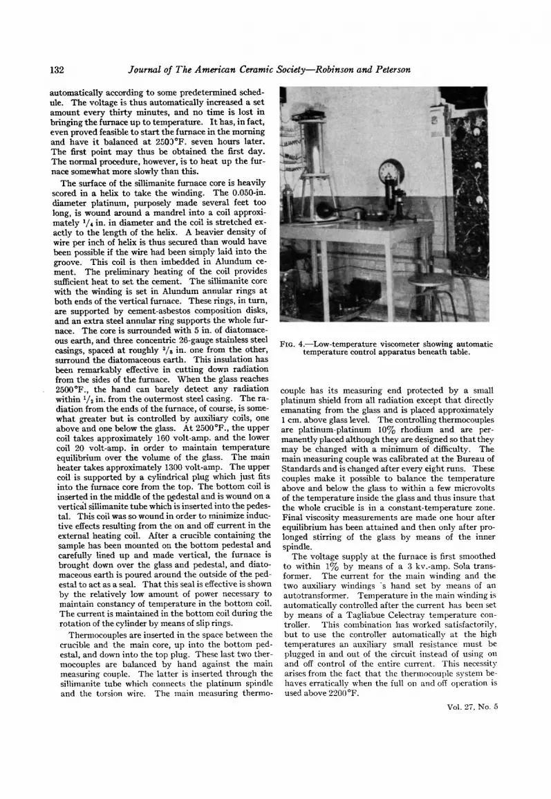
FIG. 4.-Low-temperature viscometer showing automatic temperature control apparatus beneath table.
couple has its measuring end protected by a small platinum shield from all radiation except that directly emanating from the glass and is placed approximately 1 cm. above glass level. The controlling thermocouples are platinum-platinum 10% rhodium and are per- manently placed although they are designed so that they may be changed with a minimum of difficulty. The main measuring couple was calibrated at the Bureau of Standards and is changed after every eight runs. These couples make it possible to balance the temperature above and below the glass to within a few microvolts of the temperature inside the glass and thus insure that the whole crucible is in a constant-temperature zone. Final viscosity measurements are made one hour after equilibrium has been attained and then only after pro- longed stirring of the glass by means of the inner spindle.
The voltage supply at the furnace is first smoothed to within 1% by means of a 3 kv.-amp. Sola trans- former. The current for the main winding and the two auxiliary windings 's hand set by means of an autotransformer. Temperature in the main winding is automatically controlled after the current has been set by means of a Tagliabue Celectray temperature con- troller. This combination has worked satisfactorily, but to use the controller automatically a t the high temperatures an auxiliary small resistance must be plugged in and out of the circuit instead of using 011
and off control of the entire current. This necessity arises from the fact that the thermocouple system be- haves erratically when the full on and off operation is usedabove2200"F.
Val. 27. No. 5
C’iscosity of Recent Container Glass 133
(9 ) Low-Temperature Viscometer (45O0-65Ooc.) As stated previously, a different type of apparatus
is necessary when measuring extremely high viscosities from that used to measure lower viscosities. The sim- plest and most direct means for carrying out viscosity measurements in the range between 1Olo and 10l6 poise is by means of a fiber-elongation method. Measure- ments by this method have been carried out by many people but most intensively by Taylor and his students4 with the apparatus previously designed by Norton3 (see Fig. 4).
The furnace has the central 12 in. of the fiber cavity a t constant temperature, which is accomplished first by setting the approximate temperature of the furnace in the center coil and increasing the voltage on auxiliary end coils until they match the central temperature. A Variac control was used for this purpose. Balance was then maintained between the end and middle coils by means of a simple photoelectric setup, in which the dif- ferential from a thermocouple is applied directly across a sensitive galvanometer, which in turn reflects a light beam across the photocell. This photocell controls a relay which plugs an auxiliary resistance in or out of the end circuits. The temperature of the central part of the furnace is maintained by means of the lever ar- rangement described by N ~ r t o n . ~ This arrangement uses the expansion and contraction of the furnace core as an accentuating mechanism through a 40- to 1-lever to operate a series resistance. This furnace is likewise run from a Sola constant voltage transformer.
In making a determination, glass fibers are first drawn by hand from the sample and cut into lengths about 10 in. long. These fibers range from 0.5 to 1 mm. in diameter. The fiber has a small glass bead fused on
. one end and is hung from a stirrup, which in turn is sus- pended from the top of the furnace. A second stirrup is then suspended from the bottom of the fiber by means of a bead fused on the lower end of the glass. A third stirrup for c q i n g the weights is fastened to the second stirrup by means of, a wire and spherically seated links. The total weight of the bottom wire and stirrup as- sembly is exactly 10 gm.
(3) Softening Point Furnace The temperature a t which the viscosity is 4.5 X
107 poise is measured on a small softening-point furnace. The design, construction, and operation of such a fur- nace have been described by Littleton.?
The measured values of the softening point may be compared with the value of log viscosity equal to 7.65 as calculated from the Fulche9 equation. The con- stants of the equation were obtained by a least squares calculation, using the measured viscosity points. The comparison is given in Table I.
The differences between measured and calculated points are predominantly negative, probably indicating that the primary standard is about two degrees low.
7 J . T. Littleton, Jr., “Method for Measuring Softening Temperature of Glasses,” Jozrr. .4mer. Ceram. SOC., 10 [4]
* G. S. Fulrher, “Analysis of Recent Measurements of Viscosity of Glasses,” ibid.. 8 161 339-55 (1925).
259-63 (1027).
(!944)
TABLE I . MEASURED vs. LEAST SQUARE CALCULATED SOFTENING
Inasmuch as this was initially furnished with an esti- mated error of f 2 “C., the check is seen to be satisfac- tory.
111. Calculation of Results
( I ) High-Temperature Viscometer There are two methods in use by which the viscosity
at high temperatures can be calculated. The first of these consists in rotating the outer aucible at a constant speed and measuring’the angular deflection of the inner cylinder by means of a mirror and scale arrangement. This method is used when the viscosity is less than 50,000 poise. For higher viscosities, it is impossible to find torsion wires which are heavy enough and which obey Hooke’s law sufficiently accurately to make them satisfactory as suspensions. In this case, the so-called aperiodic method is used. In this method, the outer mcib le is turned slowly by hand until the deflection shown on the scale is greater than 30 cm. from the ini- tial position of rest. Because of the extreme viscosity of the liquid glass, the spindle returns to its zero posi- tion very slowly. The time of transit of the light beam across the scale is taken between several sets of points, in this case between deflections of 30 and 20 cm. and of 15 and 5 cm. The deflection is made in both direc- tions, and it is important that the rest position of the inside spindle be such that the position of the light beam registers accurately on zero under no torque. It is thus possible to extend the viscosity range up to approxi- mately 3 X 1 0 6 or 3 million poise. It is the extension of the viscosity range by this aperiodic method which makes an apparatus of this type so valuable for meas- uring viscosities. There are, in fact, very few other methods by which it would be possible, as it is in this case, to measure viscosities from the extreme low range of 0.1 to several million poise.
The method used for calculating the results in the periodic case is well known and can be shown by equa- tion (1).
KDt Dt q = 4nCdLE = const. x
7 = viscosity (poise).
134 Journal of The A m e r h n Ceramic Society-Robinson and Peterson
D = scale of de5ecgon (cm.). is very small. Ferry and Parks” have reported values t of d(log v ) / d ( l / T ) for polyisobutylene as low as 0.3 c =- 4dRi)YRr):. of those found for glucose. It appeared t o be of interest - (Riy to repeat the calibration in sitzl at room temperature Ri = crucible radius (cm.). Rx = spindle radius (cm.). at the higher viscosities in this laboratory.
A Vistanex sample submitted to the Bureau of Stand- For the present crucibles, the average inside diameter ards was reported t o have a viscosity of 2063 * O.20/, varies from 6.342 t o 6.457 cm. Greater variations pie- poise at 20°C. and 732.6 * 0.2% poise at 30°C. The sumably can also occur. Because the radius of the plati- sample was then run in this laboratory at 22°C. and at num spindle is 0.477 cm. a t room temperature, a change 26°C. These temperatures were selected as being in the‘ external diameter from 6.198 to 6.604 cm. will slightly above room temperature and were maintained cause a change in the apparatus consant C from 2.928 by the Celectray controller with a Chromel-Alumel t o 2.920. The average of this constant is 2.924, which couple in exactly the same way that it is used at ele- bears out the contention previously expressed that small vated temperatures. The temperatures were measured variations in the diameter of the outside crucible have by means of a copper constantan couple calibrated at relatively little effect on the calculated viscosity. The the Bureau of Standards. In this calibration, i t was extreme variation in diameter from 6.2 to 6.6 cm. assumed that log 7) for Vistanex varies linearly with changes the viscosity only by +0.13%. The actual l/T(”K.) over the short (10°C.) range of interest. variation in diameter is seen to be much less. The average of a number of determinations made in
this laboratory gave an effective spindle length, L, of d = scale distance from torsion wire (em.) ; a circular 4.57 cm., which is within 1% of the value 4.53 inherent
in Lillie’s calculation. In view of the fact that the Lillie scale at a radius of 99 cm. has been used; an error of 1 mm. here will cause an error of * 0.1%.
L = effective spindle length, determined by calibration to calibration was made on several liquids over a wide vis- be equal to 4.53 cm.; may be checked to within 1%; cosity range, his value has been assumed for all calcula- a discussion of this calibration is given later. tions used in this paper. It has been possible to show, E = volume temperature expansion factor for spindle; this factor is equal to 1.04 for at l m ~ to moreover, that the Lillie calibration using glucose is 130O0C., which is the middle of the measured range. correct. Inasmuch as there is no reason to suspect his The error in this term is slightly under 1%. calibration obtained by the use of castor oil and because
K = torque constant of spring (dyne cm./radian of twist). i t also checks the 4.53 figure, further evidence has now been obtained that the original Washburn work was in error. This Same has also hen found and dis. cussed by proctor and D ~ ~ ~ ~ ~ ~ ~ o w and inferred by
glucose calibrations are incorrect.
= time of revolution of outer crucible (seconds).
The numerical factor, 4nCdE, is found to equal 3783 for this apparatus at elevated temperatures; i t is 4%
For a spindle of the type described, Lillie’(‘) was able to derive an effective spindle length of 4.53 cm. by using
able of giving absolute results and which he has fully described. He also showed that this factor was con- stant for liquids whose viscosities range from 5 to 3500
lower at room temperature because thenis equal to 1. Babcock.io:b) It cannot be assumed, however, that all . In the aperiodic method, the viscosity is calculated a method which W n t i a 1 b makes the apparatus cap- from formula (2), which was derived by Lillie.l(a*b)
(2 )
T, - ri = time (seconds for spiildle to return from angle
0.4343K
ECL log 2 T = (Tz - Ti)
poise. Ever since the initial work of Washburn and 0, S h e l t ~ n . ~ there has been some doubt about the con- stancy of calibration of concentric cylinder viscometers over a wide range of viscosities. This lack of constancy, which has not been found by other investigators, is unvuestionably spurious and was probably caused by a skin formation over the surface of the glucose used as a calibrating liquid.io(”) Lilliei(“) also used glucose as a standard medium. In recent years, commercial de- velopment of the polyisobutylenes has placed in the hands of rheologists an important new viscosity cali- brating liquid. Aside from being available over a wide viscosity range, its temperature coefficient of viscosity
ez to angle el).
lX89 (in this particular case). Log 01/82 for distance between 30 and 20 cm. on scale =
Log &/0z for scale distance between 15 and 5 cm. = 0.4736. K, E, C, and L are same as those in equation (1).
Thus for suspension number 3, which has a torsion constant equal to 1.252 X lo5, the viscosity will be given by 8.333 x 10³ x T , - Ti when timing between the 15- and 5-cm. marks and by 2.338 x 1134 x T1 - TI between the 30- and 20-cm. marks. The evaluation of the viscosity then is extremelv simple for i t is necessary
9 E. W. Washburn and G. R. Shelton, “Viscosities and Surface Tensions of Soda-Lime-Silica Glasses at High Tem- peratures: I, Viscosities of Glasses a t High Tempera- tures,” Univ. Ill. Eng. Exfit. Station Bull., No. 140, pp. 8-50 (April 14, 1924); Ceram. Abs., 3 1121 33644 (1924).
‘0 (a) R. F. Proctor and R. W. Douglas, “Measure- ment of Viscosity of Glass at High Temperatures by Ro- tating Cylinder Viscometer,” Jour. SOC. Glass Tech., 13 [51] 194-213 (1929); Ceram. Abs., 9 151 340 (1930).
C. L. Babcock, “Vj;cosity and Electrical Conduc- tivity of Molten Glasses, J e w . Amer. Ceram. SOC., 17 [ 11 1 329-42 (1934).
( b )
~~
only to multiply this constant by the time required. The periodic method is equally simple because it is possible again to build up a table of constants for each calibrated torsion wire a t each speed and then to mul- tiply a specific constant times the deflection as noted on the scale.
The degree of reproducibility of the measurements made by this apparatus is high (see Table 11). Three
J. D. Ferry and G. S. Parks, “Viscous Properties of
* Glass No. 51 contains +0.21 Cr&. t Letters D, C, F, E, H, I, G, A, and B denote glasses evaluated by Owens and Emanuel see footnote 13, p. 137.
separate runs made by two different observers over a period of more than a year have been fitted to equation (3) by a least squares calculation.
(3)
The three constants A , B, and To were thus evaluated, and the temperatures corresponding to various values of log 7 were calculated. An equation of this type was first given by Fulcher.*
Table I1 also shows a similar calculation for a glass viscosity run both at the Coming Glass Works and at this laboratory. The agreement is satisfactory.
(9) Low-Temperature Viscometer The formula for determining the viscosity by this
method is well known (see equation (4)). A derivation is given by Lewis, Squires, and Broughton.'*
n
F = extending force (dynes). 1 = fiber length (cm.). A = fiber area (sq. cm.). dl/dt = elongation rate (cm./s&ond).
(4)
1' W. K. Lewis, Lombard Squires, and Geoffrey Brough- ton, Industrial Chemistry of Colloidal and Amorphous Materials, p. 24, Macmillan Co., New York, 1942. 540 pp.
(1944)
It is convenient t o make two substitutions for ease in manipulation. These are to replace the area by the volume (the volume remains constant throughout a determination; the area does not) and to express d / d t in centimeters per minute. With these changes, it is easy t o derive equation (5).
20mgl' Vdl/dt
r l = - (5)
m = appended mass (gm).
By separating the variables in this equation and putting in the general limits, 1 = Lo when t = TO and 1 = L when t = T, the equation can be integrated and equation (6) is obtained. Instead of measuring the
q = 19,600- - "'L, (TI - TO) . Y d - diameter of the fiber at the point of measurement, i t is thus only necessary t o measure the volume at room temperature and t o correct this volume by means of the coefficient of expansion of the glass. In the normal procedure, the volume of the fiber is measured both before and after the run and the average of the two readings is taken. This measurement is made by cali- pering the diameter of the fiber at the top, middle, and bottom at any one diameter and at right angles to this diameter. The fibers have been carefully selected be- forehand for constancy of diameter and "roundness." When viscosities are t o be measured below the anneal-
136 Journal of The American Ceramic Society-Robinson and Peterson
TBLE IV CONSTANTS FOR FULCHER EQUATION* AND VISCOSITY TEMPERATURE RESULTS FOR GLASSES CALCULATED BY LEAST
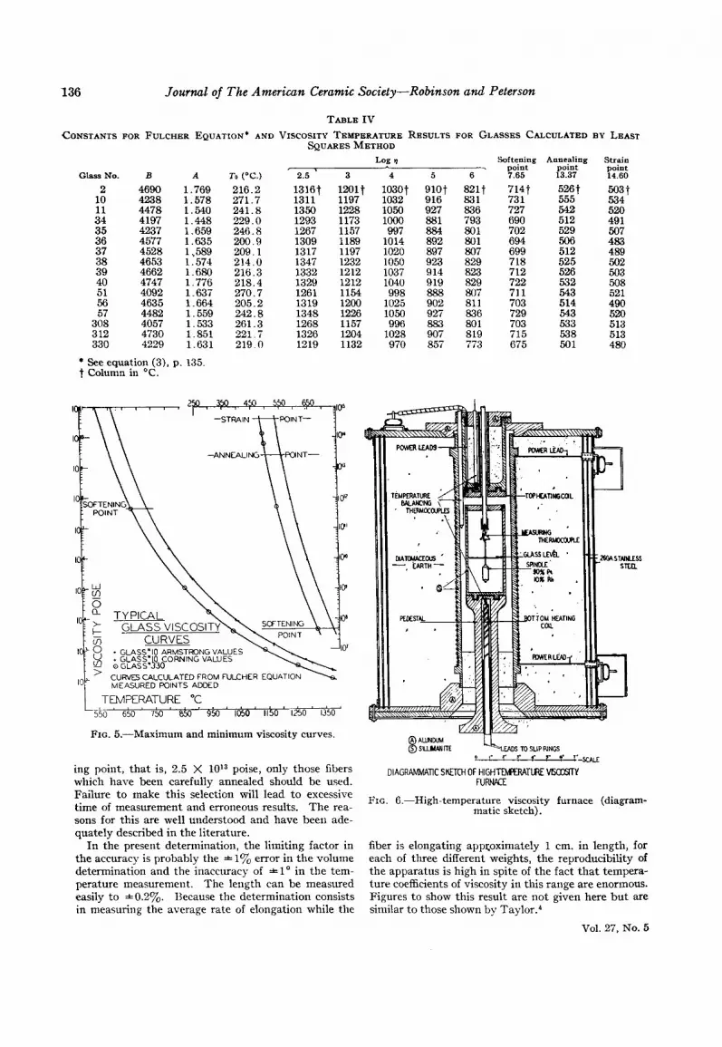
ing point, that is, 2.5 X 10¹³ poise, only those fibers which have been carefully annealed should be used. Failure to make this selection will lead to excessive time of measurement and erroneous results. The rea- sons for this are well understood and have been ade- quately described in the literature.
In the present determination, the limiting factor in the accuracy is probably the * 1% error in the volume determination and the inaccuracy of * 1 O in the tem- Derature measurement. The length can be measured
fiber is elongating apptoximately 1 cm. in length, for each of three different weights, the reproducibility of the apparatus is high in spite of the fact that tempera- ture coefficients of viscositv in this range are enormous. - -
easily to *0.20/0. Because the determination consists in measuring the average rate of elongation while the
Figures to show this result are not given here but are similar to those shown by Tay10r.~
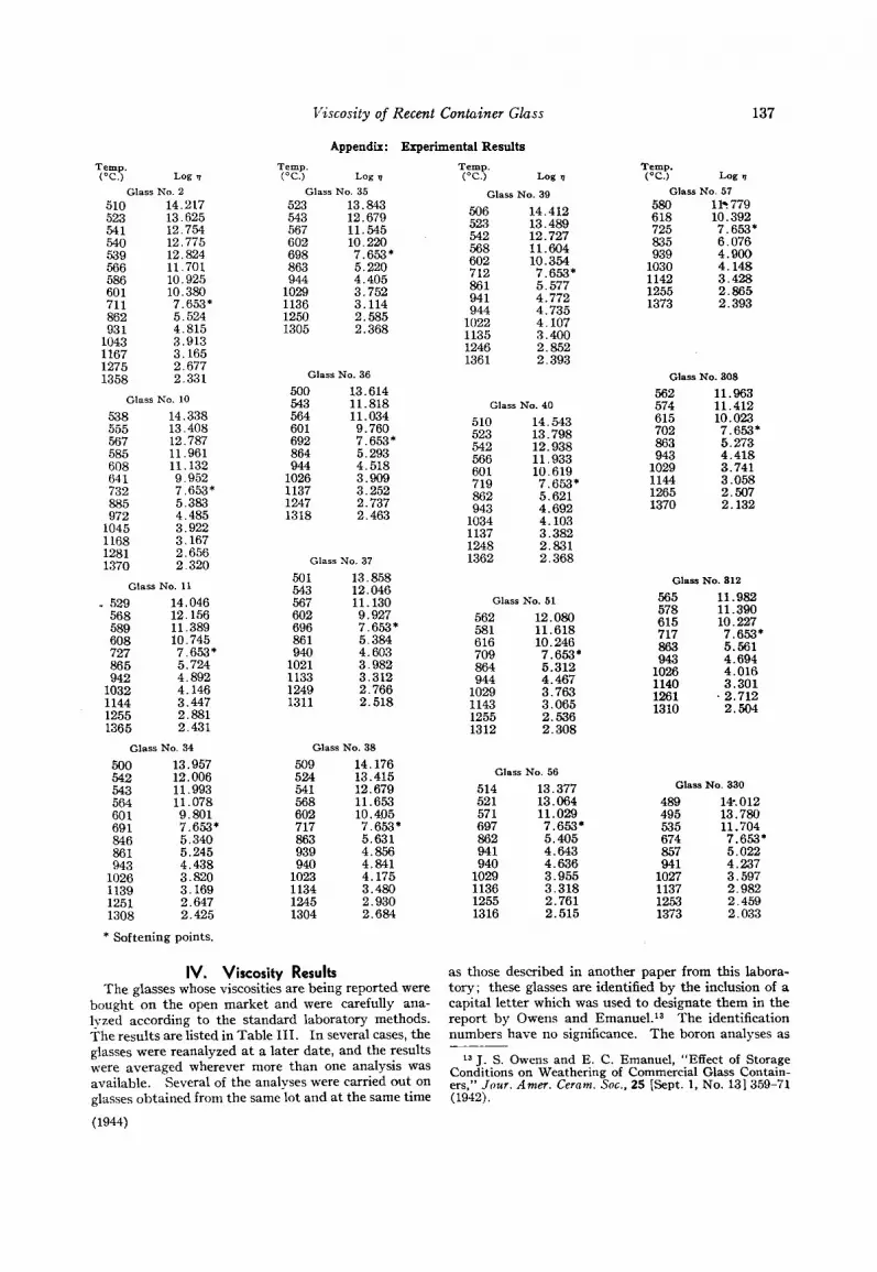
IV. Viscosity Results The glasses whose viscosities are being reported were
bought on the open market and were carefully ana- lyzed according to the standard laboratory methods. The results are listed in Table 111. In several cases, the glasses were reanalyzed a t a later date, and the results were averaged wherever more than one analysis was available. Several of the analyses were carried out on glasses obtained from the same lot and a t the same time
(1944)
as those described in another paper from this labora- tory; these glasses are identified by the inclusion of a capital letter which was used to designate them in the report by Owens and Eman~e1. l~ The identification numbers have no significance. The boron analyses as
13 J. S. Owens and E. C. Emanuel, "Effect of Storage Conditions on Weathering of Commercial Glass Contain- ers," Jour. Amer. Cernm. Soc.. 25 [Sept. 1, No. 131 359-71 (1942).
138 Journal of The American Ceramic Society-Zarbo, Hunt, and Smith
given may be slightly high; glasses Nos. 40 and 312 have been checked spectroscopically for boron. Check analyses run in several other laboratories in an effort to substantiate these boron results have shown that present methods for this element are not entirely reli- able.
In determining the viscosities, i t is impossible to measure every glass at a common set of temperatures. This means that i t is difficult to compare results between various glasses. Each glass, therefore, has been fitted by least squares methods to equation (3) and the three constants, A , B, and To, have been calculated.
B T - To h g v = --A + - (3)
The fit between experiment and empirical formula is within 0.5%. There can be no question but that this equation gives a true and accurate representation of the connection between viscosity and temperature for soda- lime glasses when measured by the method described. It should be pointed out that this includes not only cal- cite but also dolomitic glasses. Several other types of three- and four-constant equations were tried without success (equations (7) and (8)).
(7)
’ (8) Logs = A - Blog T - - + - Equations (7) and (S), for example, cannot even be con- sidered as empirical equations L-------- +h e fit is too bad.
C D T Tg
The Waterton equation,I4 bec; ~- nnt
l4 S . C. Waterton, “Viscous-Temperature RelaLL, and Some Inferences on Nature of Molten and Plastic Glass,” lour . SOC. G k w Tech., 16 1621 244-53 (1932); Ceram. Abs., 11 [12] 609 (1932).
lend itself easily to a least squares cakulation. The success of the simple Fulcher equation is surprising, particularly in view of the fact that the more elaborate equations give so poor a fit.
The constants for the Fulcher equation and the tem- peratures calculated from them at several constant log viscosities are given in Table IV. Results are shown in Fig. 5, and the experimental results are listed in the Appendix.
In Table IV, the columns marked softening, anneal- ing, and strain points represent temperatures calcu- lated for log viscosity, 7.65, 13.37 and 14.60, respec- tively, from data measured at constant temperature by the method already described. Like the softening points, the annealing points obtained in this way check the results obtained in other laboratories by the normal methods very closely. The agreement at the strain point is open to question, however, as the error in this determination from any one laboratory is probably +20”. It can be shown, however, that the log 7 ) versus T (OK.) curves for these glasses are essentially straight lines, a t least between 1013 and 1015 poise. Marked deviations from straight lines, such as are sometimes found a t the strain point, are undoubtedly the result of the strain-point apparatus or some other cause and do not represent a property of the glass itself.
Acknowledgment The authors acknowledge with thanks several helpful
conversations with H. R. Lillie and Nelson W. Taylor on the subject matter of this paper. Much of the engineering of the apparatus was worked out with C. C. Schrader of this laboratory. The two furnaces were constructed by the H. E. Trent Company of Philadelphia according to
ecifications of the writers. Figure 6 is a line drawing )m one of their working drawings and is reproduced
with their permission.
LANCASTER, PENNSYLVANIA ARMSTRONG CORK COUPAN9
ANALYSIS OF CORDS AND STONES* BY G . J. ZARBO, H. J. HUNT, AND D. C. SMITH
ABSTRACT A method is described for the separation of cords and stones from the surrounding
glass, and procedures are given for the semimicro-determination of silica and alumina. The apparatus is illustrated. Analytical results by full-scale methods and semimicro- methods are given. The methods of semimicro-analysis are shown to be rapid and accurate.
1. Introduction When stones or cords occur during the production of
glass, the identification of the contaminating material is highly desirable. The quickest method, of course, is a petrographic examination, which includes the deter- mination of the refractive index and other optical char- acteristics of any crystalline material present. Chem- ical analysis, however, is the only means of identifica-
* Presented at the Glass Division Autumn Meeting, At)secon, N. J., September 19, 1912. Received December I ( \ . 1943.
tion if no crystals are present. Even when petro- graphic analysis is possible, i t is sometimes desirable to check the findings by means of a chemical analysis, either on the crystals themselves or on the entire inclu- sion.
The inclusion is sometimes large enough to permit a full-scale analysis. When the available samples are too small for analysis by ordinary methods, i t is necessary either to analyze a number of lumps collectively or to investigate a single lump by semimicro-methods.
The semimicro-method, applied to a single lump, possesses several advantages.