University of Pennsylvania ScholarlyCommons Departmental Papers (ESE) Department of Electrical & Systems Engineering December 2006 Piezoelectric Aluminum Nitride Vibrating Contour-Mode MEMS Resonators Gianluca Piazza University of Pennsylvania, [email protected]Philip J. Stephanou University of California Albert P. Pisano University of California Follow this and additional works at: hp://repository.upenn.edu/ese_papers Copyright 2006 IEEE. Reprinted from Journal of Microelectrochemical Systems, Volume 15, Issue 6, December 2006, pages 1406-1418. is material is posted here with permission of the IEEE. Such permission of the IEEE does not in any way imply IEEE endorsement of any of the University of Pennsylvania's products or services. Internal or personal use of this material is permied. However, permission to reprint/republish this material for advertising or promotional purposes or for creating new collective works for resale or redistribution must be obtained from the IEEE by writing to [email protected]. By choosing to view this document, you agree to all provisions of the copyright laws protecting it. is paper is posted at ScholarlyCommons. hp://repository.upenn.edu/ese_papers/223 For more information, please contact [email protected]. Recommended Citation Gianluca Piazza, Philip J. Stephanou, and Albert P. Pisano, "Piezoelectric Aluminum Nitride Vibrating Contour-Mode MEMS Resonators", . December 2006.
Transcript
University of PennsylvaniaScholarlyCommons
Departmental Papers (ESE) Department of Electrical & Systems Engineering
Follow this and additional works at: http://repository.upenn.edu/ese_papers
Copyright 2006 IEEE. Reprinted from Journal of Microelectrochemical Systems, Volume 15, Issue 6, December 2006, pages 1406-1418.
This material is posted here with permission of the IEEE. Such permission of the IEEE does not in any way imply IEEE endorsement of any of theUniversity of Pennsylvania's products or services. Internal or personal use of this material is permitted. However, permission to reprint/republish thismaterial for advertising or promotional purposes or for creating new collective works for resale or redistribution must be obtained from the IEEE bywriting to [email protected]. By choosing to view this document, you agree to all provisions of the copyright laws protecting it.
This paper is posted at ScholarlyCommons. http://repository.upenn.edu/ese_papers/223For more information, please contact [email protected].
Recommended CitationGianluca Piazza, Philip J. Stephanou, and Albert P. Pisano, "Piezoelectric Aluminum Nitride Vibrating Contour-Mode MEMSResonators", . December 2006.
AbstractThis paper reports theoretical analysis and experimental results on a new class of rectangular plate and ring-shaped contour-mode piezoelectric aluminum nitride radio-frequency microelectromechanical systemsresonators that span a frequency range from 19 to 656 MHz showing high-quality factors in air (Qmax = 4300at 229.9 MHz), low motional resistance (ranging from 50 to 700 Ω), and center frequencies that arelithographically defined. These resonators achieve the lowest value of motional resistance ever reported forcontour-mode resonators and combine it with high Q factors, therefore enabling the fabrication of arrays ofhigh-performance microresonators with different frequencies on a single chip. Uncompensated temperaturecoefficients of frequency of approximately 25 ppm/°C were also recorded for these resonators. Initialdiscussions on mass loading mechanisms induced by metal electrodes and energy loss phenomenon areprovided.
CommentsCopyright 2006 IEEE. Reprinted from Journal of Microelectrochemical Systems, Volume 15, Issue 6, December2006, pages 1406-1418.
This material is posted here with permission of the IEEE. Such permission of the IEEE does not in any wayimply IEEE endorsement of any of the University of Pennsylvania's products or services. Internal or personaluse of this material is permitted. However, permission to reprint/republish this material for advertising orpromotional purposes or for creating new collective works for resale or redistribution must be obtained fromthe IEEE by writing to [email protected]. By choosing to view this document, you agree to allprovisions of the copyright laws protecting it.
This journal article is available at ScholarlyCommons: http://repository.upenn.edu/ese_papers/223
Gianluca Piazza, Member, IEEE, Philip J. Stephanou, Member, IEEE, and Albert P. (Al)Pisano
Abstract—This paper reports theoretical analysis and experi-mental results on a new class of rectangular plate and ring-shapedcontour-mode piezoelectric aluminum nitride radio-frequencymicroelectromechanical systems resonators that span a frequencyrange from 19 to 656 MHz showing high-quality factors in air(Qmax = 4300 at 229.9 MHz), low motional resistance (rangingfrom 50 to 700), and center frequencies that are lithographicallydefined. These resonators achieve the lowest value of motional re-sistance ever reported for contour-mode resonators and combineit with high Q factors, therefore enabling the fabrication of arraysof high-performance microresonators with different frequencieson a single chip. Uncompensated temperature coefficients offrequency of approximately 25 ppm C were also recorded forthese resonators. Initial discussions on mass loading mechanismsinduced by metal electrodes and energy loss phenomenon areprovided. [2006-0019]
Index Terms—Aluminum nitride, contour-mode resonators, mi-croelectromechanical systems (MEMS) resonators, piezoelectricresonators, radio-frequency (RF) MEMS.
I. INTRODUCTION
THE demand of consumer electronics for radio-frequency(RF) filters and frequency reference elements has focused
attention on the reduction of size, power consumption, and priceand pushed current research interests towards the manufacturingof a single-chip integrated RF solution. Vibrating contour-modemicroelectromechanical system (MEMS) resonators constitutea very promising technology for ultimately realizing this vision.
Several electrostatically transduced micromechanicalresonators have been demonstrated in the very-high- andultra-high-frequency spectra [1]–[4]; despite their sheer highQ on the order of 10 000, they exhibit large values of motionalresistance (hundreds of k ), which ultimately complicatesthe interfacing of these electrostatic devices to 50 RF sys-tems. The low electromechanical coupling coefficient of thesurface-based electrostatic transduction mechanism cannot besufficiently improved without introducing ultrasmall air gaps(less than 20 nm) in the fabrication process. Furthermore, recentefforts [5]–[8] trying to act on geometrical parameters, such asthe effective actuation area, in order to reduce the equivalent
Manuscript received February 13, 2006; revised July 8, 2006. This workwas supported by CSAC-DARPA under Grant NBCH1020005. Subject EditorS. Lucyszyn.
G. Piazza is with the Department of Electrical and Systems Engineering, Uni-versity of Pennsylvania, Philadelphia, PA 19104 USA.
P. J. Stephanou and A. P. Pisano are with the Department of MechanicalEngineering, University of California, Berkeley, CA 94720 USA.
Color versions of Figs. 1–4, 6, 7, 12, 14, and 15 are available online at http://ieeexplore.ieee.org.
Digital Object Identifier 10.1109/JMEMS.2006.886012
motional resistance have not shown very significant improve-ments. Recently proposed “internal” electrostatic transduction[9], [10] represents a potential method for reducing the mo-tional resistance of these resonators, but it is still an unproventechnology and suffers from the need of large bias voltagesthat ultimately limit the reliability of ultrathin layers of high-Kdielectrics and intrinsic large capacitance values that mask theresonator response at high frequencies.
Piezoelectric materials such as aluminum nitride or quartzinherently offer order of magnitude larger electromechanicalcoupling coefficients. Body forces produced by thin piezo-electric elements have been successfully exploited in surfaceacoustic wave (SAW) devices [11], film bulk acoustic waveresonators (FBARs) [12], and shear-mode quartz resonators[13], achieving gigahertz frequencies and demonstrating highQ factors. Despite being a proven technology, SAW devices donot scale well to RF applications due to the resulting need forsubmicrometer lithography and decreasing power handling ca-pabilities. Moreover, FBARs and shear-mode quartz resonatorsdo not permit economical manufacturing of a single-chip RFmodule because multiple frequencyselective arrays of piezo-electric resonators cannot be easily fabricated on the samesubstrate since film thickness determines the frequency.
This paper introduces a new class of aluminum nitride piezo-electric resonators that have their fundamental frequency de-fined by in-plane dimensions, which are prescribed at the com-puter-aided design (CAD) layout level. For this reason the de-vices are called contour-mode resonators. The use of contourmodes (with frequencies determined by in-plane dimensionsand not film thickness as for FBARs or shear quartz resonators)permits the batch fabrication of arrays of piezoelectric microres-onators with different frequencies on a single chip. These de-vices, realized in the shape of plates or rings, uniquely combinemultiple frequencies with the ability to interface directly with50 systems (by means of a low motional resistance generallyvarying between 50 and 700 ) and achieve high quality fac-tors (as high as 4300 at 230 MHz) in air. The next sections willfocus on the electromechanical analysis of these resonators, thetechniques used for their fabrication, and their electrical perfor-mance and offer discussions on the temperature dependence andmass sensitivity of their center frequency and energy loss mech-anisms.
II. DESIGN OF RECTANGULAR PLATE RESONATORS
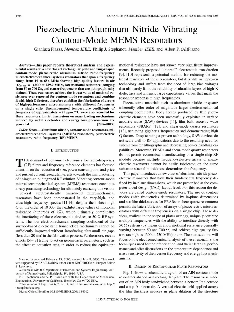
Fig. 1 shows a schematic diagram of an AlN contour-moderesonators shaped as a rectangular plate. The resonator is madeout of an AlN body sandwiched between a bottom Pt electrodeand a top Al electrode. A vertical electric field applied acrossthe film thickness induces in plane dilation of the structure
Fig. 1. Schematic representation of one-port AlN contour-mode rectangularplate resonator.
through the coefficient and excites the resonator eitherin length-extensional or width-extensional mode shapes, de-pending on whether the structure vibrates primarily across itslength or width and the excitation frequency. The equivalentelectromechanical model of the resonator is derived. Firstfrequency equation and mode shapes are given, and then theequivalent parameters are computed using an energy methodbased on Mason’s derivation [14]. As will be shown, theanalysis of the most important mode shapes for the rectangularplate can be simplified to the one-dimensional case of a barvibrating across either its length or width.
The problem of in-plane vibrations of plates has been solvedin many different ways in the past [15], [16]. It is very com-plicated to obtain exact closed-form solutions; an approximatesolution that gives the frequency equation and mode shape is re-ported in [14]
(1)
where
(2)
and
(3)
where
(4)
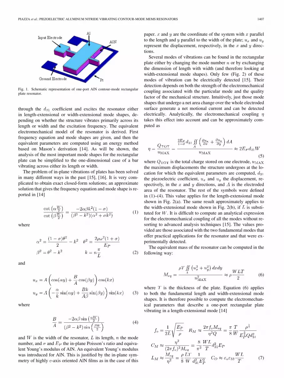
and is the width of the resonator, its length, the modenumber, and and the in-plane Poisson’s ratio and equiva-lent Young’s modulus of AlN. An equivalent Young’s moduluswas introduced for AlN. This is justified by the in-plane sym-metry of highly -axis oriented AlN films as in the case of this
paper. and are the coordinate of the system with parallelto the length and parallel to the width of the plate; andrepresent the displacement, respectively, in the and direc-tions.
Several modes of vibrations can be found in the rectangularplate either by changing the mode number or by exchangingthe dimension of length with width (and therefore looking atwidth-extensional mode shapes). Only few (Fig. 2) of thesemodes of vibration can be electrically detected [15]. Theirdetection depends on both the strength of the electromechanicalcoupling associated with the particular mode and the qualityfactor of the mechanical structure. Intuitively, just those modeshapes that undergo a net area change over the whole electrodedsurface generate a net motional current and can be detectedelectrically. Analytically, the electromechanical couplingtakes this effect into account and can be approximately com-puted as
(5)where is the total charge stored on one electrode,the maximum displacements the structure undergoes at the lo-cation for which the equivalent parameters are computed,the piezoelectric coefficient, and the displacement, re-spectively, in the and directions, and is the electrodedarea of the resonator. The rest of the symbols were definedin (1)–(4). This value applies for the length-extensional modeshown in Fig. 2(a). The same result approximately applies tothe width-extensional mode shown in Fig. 2(b), if is substi-tuted for . It is difficult to compute an analytical expressionfor the electromechanical coupling of all the modes without re-sorting to advanced analysis techniques [15]. The values pro-vided are those associated with the two fundamental modes thatoffer practical applications for the resonator and that were ex-perimentally detected.
The equivalent mass of the resonator can be computed in thefollowing way:
(6)
where is the thickness of the plate. Equation (6) appliesto both the fundamental length and width-extensional modeshapes. It is therefore possible to compute the electromechan-ical parameters that describe a one-port rectangular platevibrating in a length-extensional mode [14]
(7)
1408 JOURNAL OF MICROELECTROMECHANICAL SYSTEMS, VOL. 15, NO. 6, DECEMBER 2006
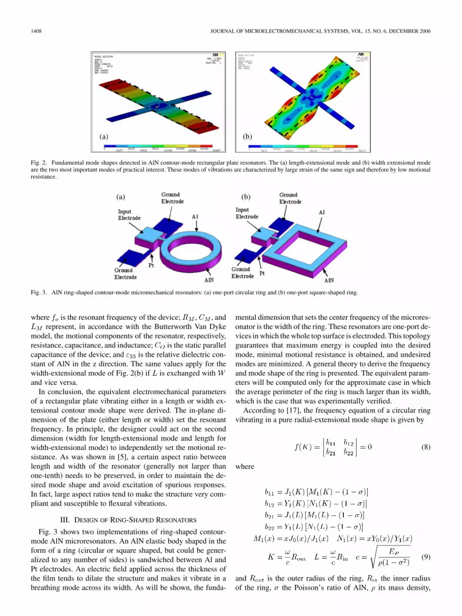
Fig. 2. Fundamental mode shapes detected in AlN contour-mode rectangular plate resonators. The (a) length-extensional mode and (b) width extensional modeare the two most important modes of practical interest. These modes of vibrations are characterized by large strain of the same sign and therefore by low motionalresistance.
Fig. 3. AlN ring-shaped contour-mode micromechanical resonators: (a) one-port circular ring and (b) one-port square-shaped ring.
where is the resonant frequency of the device; , , andrepresent, in accordance with the Butterworth Van Dyke
model, the motional components of the resonator, respectively,resistance, capacitance, and inductance; is the static parallelcapacitance of the device; and is the relative dielectric con-stant of AlN in the z direction. The same values apply for thewidth-extensional mode of Fig. 2(b) if is exchanged withand vice versa.
In conclusion, the equivalent electromechanical parametersof a rectangular plate vibrating either in a length or width ex-tensional contour mode shape were derived. The in-plane di-mension of the plate (either length or width) set the resonantfrequency. In principle, the designer could act on the seconddimension (width for length-extensional mode and length forwidth-extensional mode) to independently set the motional re-sistance. As was shown in [5], a certain aspect ratio betweenlength and width of the resonator (generally not larger thanone-tenth) needs to be preserved, in order to maintain the de-sired mode shape and avoid excitation of spurious responses.In fact, large aspect ratios tend to make the structure very com-pliant and susceptible to flexural vibrations.
III. DESIGN OF RING-SHAPED RESONATORS
Fig. 3 shows two implementations of ring-shaped contour-mode AlN microresonators. An AlN elastic body shaped in theform of a ring (circular or square shaped, but could be gener-alized to any number of sides) is sandwiched between Al andPt electrodes. An electric field applied across the thickness ofthe film tends to dilate the structure and makes it vibrate in abreathing mode across its width. As will be shown, the funda-
mental dimension that sets the center frequency of the microres-onator is the width of the ring. These resonators are one-port de-vices in which the whole top surface is electroded. This topologyguarantees that maximum energy is coupled into the desiredmode, minimal motional resistance is obtained, and undesiredmodes are minimized. A general theory to derive the frequencyand mode shape of the ring is presented. The equivalent param-eters will be computed only for the approximate case in whichthe average perimeter of the ring is much larger than its width,which is the case that was experimentally verified.
According to [17], the frequency equation of a circular ringvibrating in a pure radial-extensional mode shape is given by
(8)
where
(9)
and is the outer radius of the ring, the inner radiusof the ring, the Poisson’s ratio of AlN, its mass density,
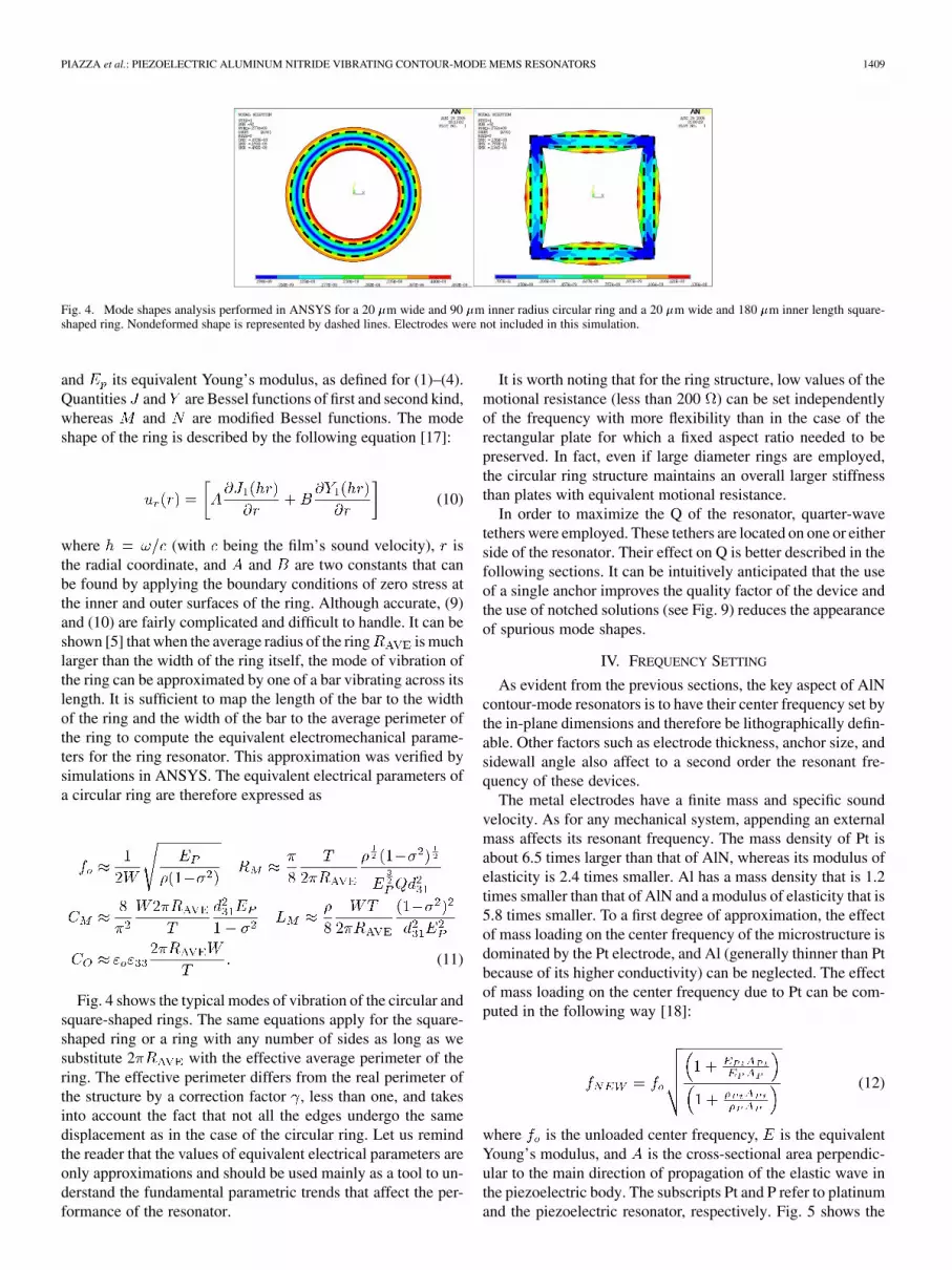
Fig. 4. Mode shapes analysis performed in ANSYS for a 20 �m wide and 90 �m inner radius circular ring and a 20 �m wide and 180 �m inner length square-shaped ring. Nondeformed shape is represented by dashed lines. Electrodes were not included in this simulation.
and its equivalent Young’s modulus, as defined for (1)–(4).Quantities and are Bessel functions of first and second kind,whereas and are modified Bessel functions. The modeshape of the ring is described by the following equation [17]:
(10)
where (with being the film’s sound velocity), isthe radial coordinate, and and are two constants that canbe found by applying the boundary conditions of zero stress atthe inner and outer surfaces of the ring. Although accurate, (9)and (10) are fairly complicated and difficult to handle. It can beshown [5] that when the average radius of the ring is muchlarger than the width of the ring itself, the mode of vibration ofthe ring can be approximated by one of a bar vibrating across itslength. It is sufficient to map the length of the bar to the widthof the ring and the width of the bar to the average perimeter ofthe ring to compute the equivalent electromechanical parame-ters for the ring resonator. This approximation was verified bysimulations in ANSYS. The equivalent electrical parameters ofa circular ring are therefore expressed as
(11)
Fig. 4 shows the typical modes of vibration of the circular andsquare-shaped rings. The same equations apply for the square-shaped ring or a ring with any number of sides as long as wesubstitute 2 with the effective average perimeter of thering. The effective perimeter differs from the real perimeter ofthe structure by a correction factor , less than one, and takesinto account the fact that not all the edges undergo the samedisplacement as in the case of the circular ring. Let us remindthe reader that the values of equivalent electrical parameters areonly approximations and should be used mainly as a tool to un-derstand the fundamental parametric trends that affect the per-formance of the resonator.
It is worth noting that for the ring structure, low values of themotional resistance (less than 200 ) can be set independentlyof the frequency with more flexibility than in the case of therectangular plate for which a fixed aspect ratio needed to bepreserved. In fact, even if large diameter rings are employed,the circular ring structure maintains an overall larger stiffnessthan plates with equivalent motional resistance.
In order to maximize the Q of the resonator, quarter-wavetethers were employed. These tethers are located on one or eitherside of the resonator. Their effect on Q is better described in thefollowing sections. It can be intuitively anticipated that the useof a single anchor improves the quality factor of the device andthe use of notched solutions (see Fig. 9) reduces the appearanceof spurious mode shapes.
IV. FREQUENCY SETTING
As evident from the previous sections, the key aspect of AlNcontour-mode resonators is to have their center frequency set bythe in-plane dimensions and therefore be lithographically defin-able. Other factors such as electrode thickness, anchor size, andsidewall angle also affect to a second order the resonant fre-quency of these devices.
The metal electrodes have a finite mass and specific soundvelocity. As for any mechanical system, appending an externalmass affects its resonant frequency. The mass density of Pt isabout 6.5 times larger than that of AlN, whereas its modulus ofelasticity is 2.4 times smaller. Al has a mass density that is 1.2times smaller than that of AlN and a modulus of elasticity that is5.8 times smaller. To a first degree of approximation, the effectof mass loading on the center frequency of the microstructure isdominated by the Pt electrode, and Al (generally thinner than Ptbecause of its higher conductivity) can be neglected. The effectof mass loading on the center frequency due to Pt can be com-puted in the following way [18]:
(12)
where is the unloaded center frequency, is the equivalentYoung’s modulus, and is the cross-sectional area perpendic-ular to the main direction of propagation of the elastic wave inthe piezoelectric body. The subscripts Pt and P refer to platinumand the piezoelectric resonator, respectively. Fig. 5 shows the
1410 JOURNAL OF MICROELECTROMECHANICAL SYSTEMS, VOL. 15, NO. 6, DECEMBER 2006
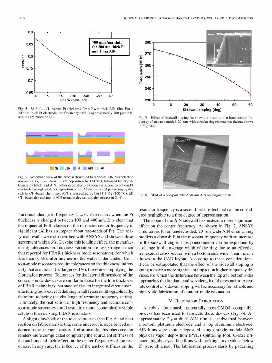
Fig. 5. Shift f =f versus Pt thickness for a 2-�m-thick AlN film. For a200-nm-thick Pt electrode, the frequency shift is approximately 700 ppm/nm.Results are based on (12).
Fig. 6. Schematic view of the process flow used to fabricate AlN piezoelectricresonators. (a) Low stress nitride deposition by LPCVD, followed by Pt pat-terning by liftoff and AlN sputter deposition; (b) open via access to bottom Ptelectrode through AlN; (c) deposition of top Al electrode and patterning by dryetch in Cl -based chemistry. AlN is wet etched by hot H PO (160 C); (d)Cl -based dry etching of AlN resonant devices and dry release in XeF .
fractional change in frequency that occurs when the Ptthickness is changed between 100 and 400 nm. It is clear thatthe impact of Pt thickness on the resonator center frequency issignificant (Al has an impact about one-tenth of Pt). The ana-lytical results were also verified with ANSYS and showed closeagreement within 3%. Despite this loading effect, the manufac-turing tolerances on thickness variation are less stringent thanthat reported for FBAR (thickness mode resonators), for whichless than 0.1% uniformity across the wafer is demanded. Con-tour-mode resonators require tolerances on the thickness unifor-mity that are about 10 larger ( 1%), therefore simplifying thefabrication process. Tolerances for the lateral dimensions of thecontour-mode devices are similar to those for the film thicknessof FBAR technology, but state-of-the-art integrated circuit man-ufacturing tools excel at defining small features lithographically,therefore reducing the challenge of accurate frequency setting.Ultimately, the realization of high frequency and accurate con-tour-mode structures could result in a more economically viablesolution than existing FBAR resonators.
A slight drawback of the release process (see Fig. 6 and nextsection on fabrication) is that some undercut is experienced un-derneath the anchor location. Unfortunately, this phenomenonrenders more complicated computing the equivalent stiffness ofthe anchors and their effect on the center frequency of the res-onator. In any case, the influence of the anchor stiffness on the
Fig. 7. Effect of sidewall sloping (as shown in inset) on the fundamental fre-quency of an unelectroded, 20-�m-wide circular ring resonator as the one shownin Fig. 9(a).
Fig. 8. SEM of a one-port 200� 50 �m AlN rectangular plate.
resonator frequency is a second-order effect and can be consid-ered negligible to a first degree of approximation.
The slope of the AlN sidewall has instead a more significanteffect on the center frequency. As shown in Fig. 7, ANSYSsimulations for an unelectroded, 20- m-wide AlN circular ringpredicts a downshift in the resonant frequency with an increasein the sidewall angle. This phenomenon can be explained bya change in the average width of the ring due to an effectivetrapezoidal cross section with a bottom side wider than the onedrawn in the CAD layout. According to these considerations,it can be extrapolated that the effect of the sidewall sloping isgoing to have a more significant impact on higher frequency de-vices, for which the difference between the top and bottom sidesapproaches the fundamental wavelength of the resonator. Accu-rate control of sidewall sloping will be necessary for reliable andhigh-yield fabrication of contour-mode resonators.
V. RESONATOR FABRICATION
A robust four-mask, potentially post-CMOS compatibleprocess has been used to fabricate these devices (Fig. 6). Anapproximately 2- m-thick AlN film is sandwiched betweena bottom platinum electrode and a top aluminum electrode.AlN films were sputter-deposited using a single-module AMSphysical vapor deposition (PVD) sputtering tool. C-axis ori-ented, highly crystalline films with rocking curve values below2 were obtained. The fabrication process starts by patterning
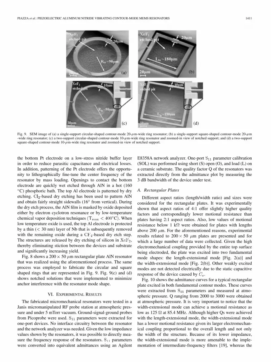
Fig. 9. SEM image of (a) a single-support circular-shaped contour-mode 20-�m-wide ring resonator; (b) a single-support square-shaped contour-mode 20-�m-wide ring resonator; (c) a two-support circular-shaped contour-mode 10-�m-wide ring resonator and zoomed-in view of notched support; and (d) a two-supportsquare-shaped contour-mode 10-�m-wide ring resonator and zoomed-in view of notched support.
the bottom Pt electrode on a low-stress nitride buffer layerin order to reduce parasitic capacitance and electrical losses.In addition, patterning of the Pt electrode offers the opportu-nity to lithographically fine-tune the center frequency of theresonator by mass loading. Openings to contact the bottomelectrode are quickly wet etched through AlN in a hot (160C) phosphoric bath. The top Al electrode is patterned by dry
etching. -based dry etching has been used to pattern AlNand obtain fairly straight sidewalls (16 from vertical). Duringthe dry etch process, the AlN film is masked by oxide depositedeither by electron cyclotron resonance or by low-temperaturechemical vapor deposition techniques C . Whenlow temperature oxide is used, the top Al electrode is protectedby a thin ( 30 nm) layer of Nb that is subsequently removedwith the remaining oxide during a -based dry etch step.The structures are released by dry etching of silicon in ,thereby eliminating stiction between the devices and substrateand significantly increasing yield.
Fig. 8 shows a 200 50 m rectangular plate AlN resonatorthat was realized using the aforementioned process. The sameprocess was employed to fabricate the circular and squareshaped rings that are represented in Fig. 9. Fig. 9(c) and (d)shows notched solutions that were implemented to minimizeanchor interference with the resonator mode shape.
VI. EXPERIMENTAL RESULTS
The fabricated micromechanical resonators were tested in aJanis micromanipulated RF probe station at atmospheric pres-sure and under 5 mTorr vacuum. Ground-signal-ground probesfrom Picoprobe were used. parameters were extracted forone-port devices. No interface circuitry between the resonatorand the network analyzer was needed. Given the low impedancevalues shown by the resonators, it was possible to directly mea-sure the frequency response of the resonators. parameterswere converted into equivalent admittances using an Agilent
E8358A network analyzer. One-port parameter calibration(SOL) was performed using short (S) open (O), and load (L) ona ceramic substrate. The quality factor Q of the resonators wasextracted directly from the admittance plot by measuring the3 dB bandwidth of the device under test.
A. Rectangular Plates
Different aspect ratios (length/width ratio) and sizes wereconsidered for the rectangular plates. It was experimentallyshown that aspect ratios of 4:1 offer slightly higher qualityfactors and correspondingly lower motional resistance thanplates having 2:1 aspect ratios. Also, low values of motionalresistance below 1 k were obtained for plates with lengthsabove 200 m. For the aforementioned reasons, experimentalresults related to 200 50 m plates are presented and forwhich a large number of data were collected. Given the highelectromechanical coupling provided by the entire top surfacebeing electroded, the plate was excited into two fundamentalmode shapes: the length-extensional mode [Fig. 2(a)] andthe width-extensional mode [Fig. 2(b)]. Other weakly excitedmodes are not detected electrically due to the static capacitiveresponse of the device caused by .
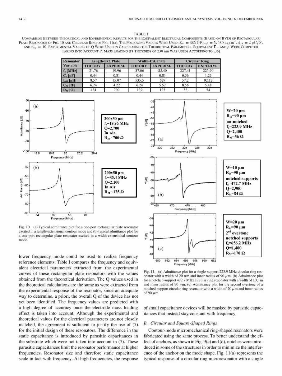
Fig. 10 shows the admittance curves for a typical rectangularplate excited in both fundamental contour modes. These curveswere extracted from parameters and measured at atmo-spheric pressure. Q ranging from 2000 to 3000 were obtainedat atmospheric pressure. It is very important to notice that thewidth-extensional mode can achieve a motional resistance aslow as 125 at 85.4 MHz. Although higher Qs were achievedwith the length-extensional mode, the width-extensional modehas a lower motional resistance given its larger electromechan-ical coupling proportional to the overall length and not onlythe width of the structure. Because of its lower impedance,the width-extensional mode is more amenable to the imple-mentation of intermediate-frequency filters [19], whereas the
1412 JOURNAL OF MICROELECTROMECHANICAL SYSTEMS, VOL. 15, NO. 6, DECEMBER 2006
TABLE ICOMPARISON BETWEEN THEORETICAL AND EXPERIMENTAL RESULTS FOR THE EQUIVALENT ELECTRICAL COMPONENTS (BASED ON BVD) OF RECTANGULAR
PLATE RESONATOR OF FIG. 10 AND CIRCULAR RING OF FIG. 11(a). THE FOLLOWING VALUES WERE USED: E = 385 GPa, � = 5; 080 kg=m , d = 2 pC=N,AND " = 10. EXPERIMENTAL VALUES OF Q WERE USED IN CALCULATING THE THEORETICAL PARAMETERS. EQUIVALENT E AND � WERE COMPUTED
TAKING INTO ACCOUNT Pt MASS LOADING (Pt THICKNESS OF 230 nm WAS USED) ACCORDING TO [36]
Fig. 10. (a) Typical admittance plot for a one-port rectangular plate resonatorexcited in a length-extensional contour mode and (b) typical admittance plot fora one-port rectangular plate resonator excited in a width-extensional contourmode.
lower frequency mode could be used to realize frequencyreference elements. Table I compares the frequency and equiv-alent electrical parameters extracted from the experimentalcurves of these rectangular plate resonators with the valuesobtained from the theoretical derivation. The Q values used inthe theoretical calculations are the same as were extracted fromthe experimental response of the resonator, since an adequateway to determine, a priori, the overall Q of the device has notyet been identified. The frequency values are predicted witha high degree of accuracy once the electrode mass loadingeffect is taken into account. Although the experimental andtheoretical values for the electrical parameters are not closelymatched, the agreement is sufficient to justify the use of (7)for the initial design of these resonators. The difference in thestatic capacitance is introduced by parasitic capacitances inthe substrate which were not taken into account in (7). Theseparasitic capacitances limit the resonator performance at higherfrequencies. Resonator size and therefore static capacitancescale in fact with frequency. At high frequencies, the response
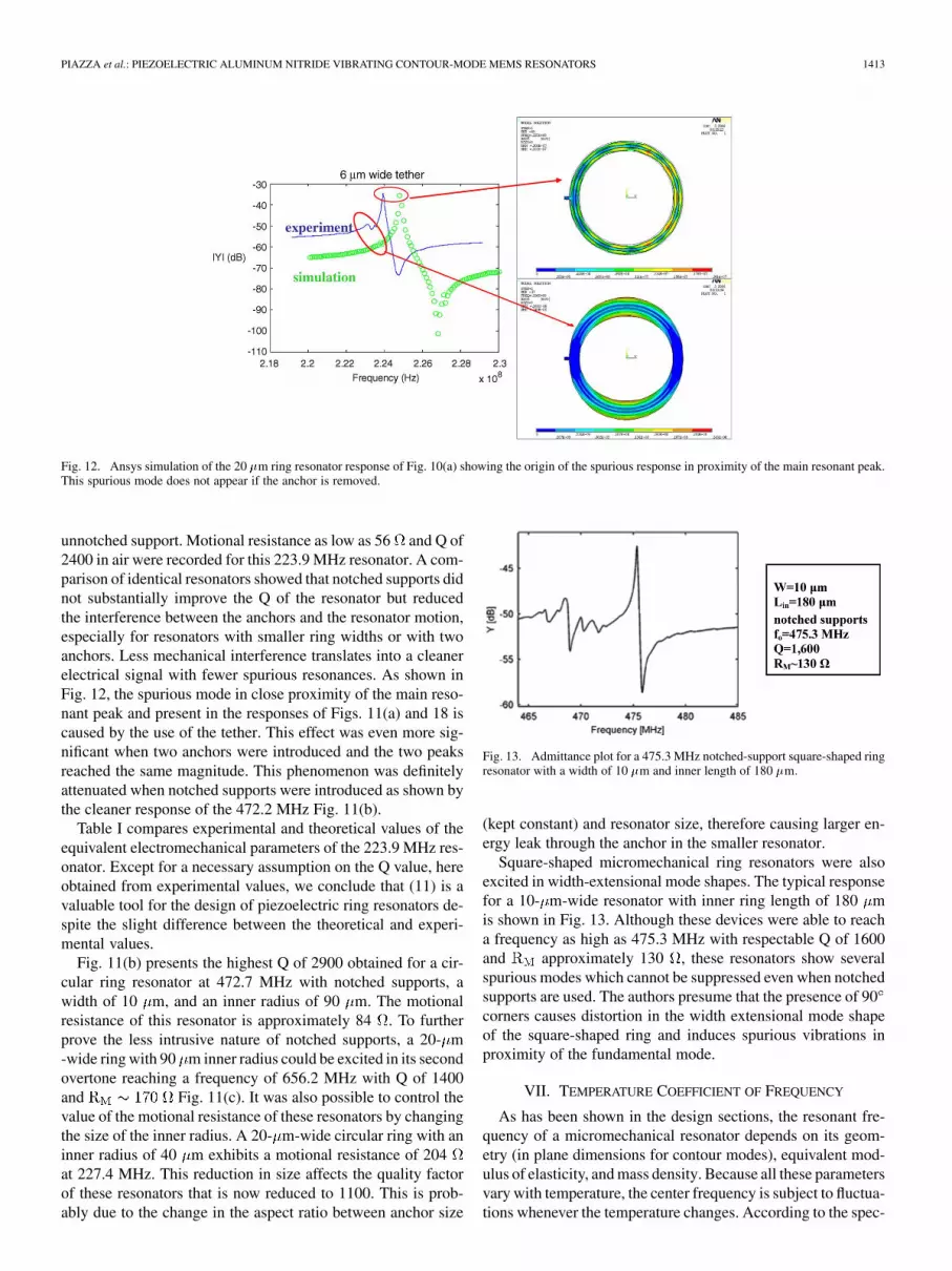
Fig. 11. (a) Admittance plot for a single-support 223.9 MHz circular ring res-onator with a width of 20 �m and inner radius of 90 �m. (b) Admittance plotfor a notched-support 472.7 MHz circular ring resonator with a width of 10 �mand inner radius of 90 �m. (c) Admittance plot for the second overtone of anotched-support circular ring resonator with a width of 20 �m and inner radiusof 90 �m.
of small capacitance devices will be masked by parasitic capac-itances that instead stay constant with frequency.
B. Circular and Square-Shaped Rings
Contour-mode micromechanical ring-shaped resonators werefabricated using the same process. To better understand the ef-fect of anchors, as shown in Fig. 9(c) and (d), notches were intro-duced in some of the structures in order to minimize the interfer-ence of the anchor on the mode shape. Fig. 11(a) represents thetypical response of a circular ring microresonator with a single
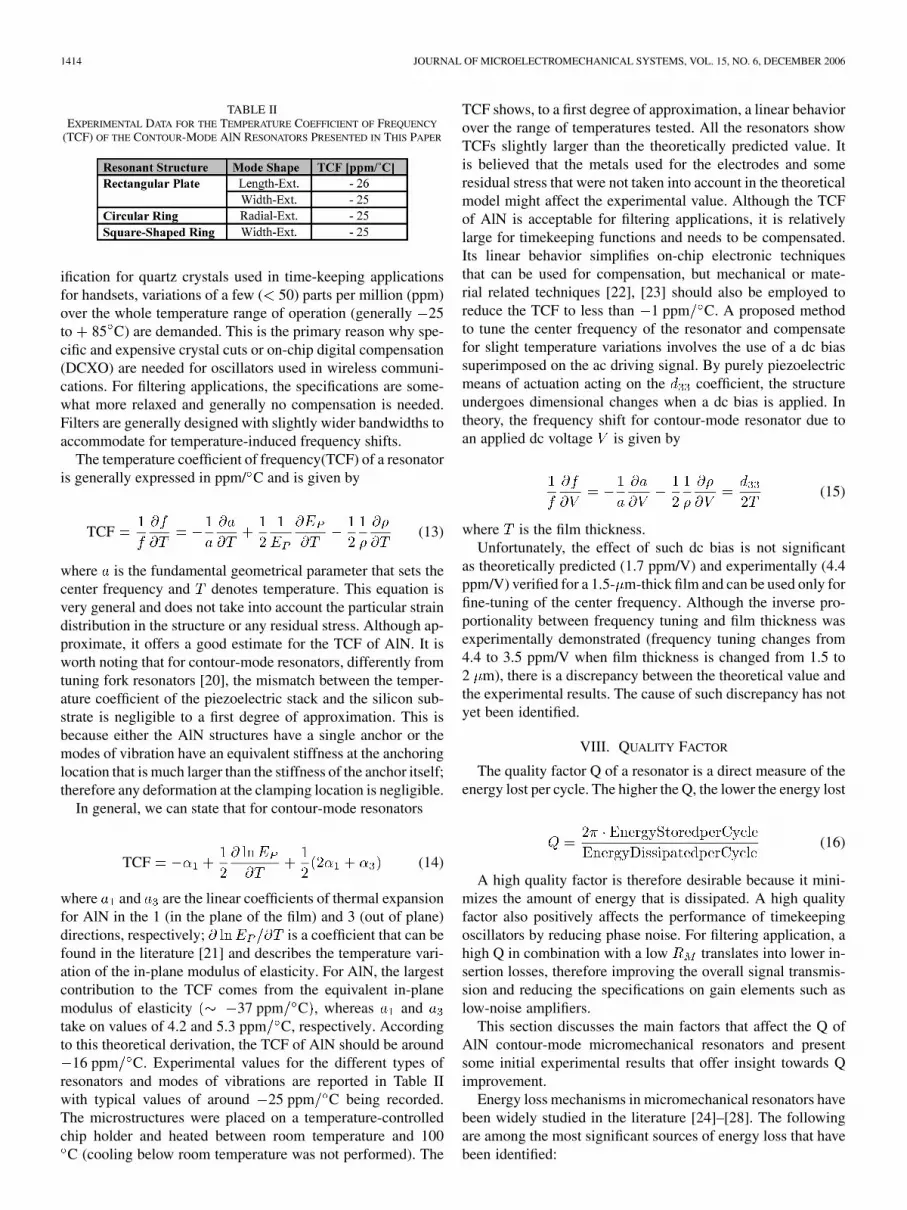
Fig. 12. Ansys simulation of the 20 �m ring resonator response of Fig. 10(a) showing the origin of the spurious response in proximity of the main resonant peak.This spurious mode does not appear if the anchor is removed.
unnotched support. Motional resistance as low as 56 and Q of2400 in air were recorded for this 223.9 MHz resonator. A com-parison of identical resonators showed that notched supports didnot substantially improve the Q of the resonator but reducedthe interference between the anchors and the resonator motion,especially for resonators with smaller ring widths or with twoanchors. Less mechanical interference translates into a cleanerelectrical signal with fewer spurious resonances. As shown inFig. 12, the spurious mode in close proximity of the main reso-nant peak and present in the responses of Figs. 11(a) and 18 iscaused by the use of the tether. This effect was even more sig-nificant when two anchors were introduced and the two peaksreached the same magnitude. This phenomenon was definitelyattenuated when notched supports were introduced as shown bythe cleaner response of the 472.2 MHz Fig. 11(b).
Table I compares experimental and theoretical values of theequivalent electromechanical parameters of the 223.9 MHz res-onator. Except for a necessary assumption on the Q value, hereobtained from experimental values, we conclude that (11) is avaluable tool for the design of piezoelectric ring resonators de-spite the slight difference between the theoretical and experi-mental values.
Fig. 11(b) presents the highest Q of 2900 obtained for a cir-cular ring resonator at 472.7 MHz with notched supports, awidth of 10 m, and an inner radius of 90 m. The motionalresistance of this resonator is approximately 84 . To furtherprove the less intrusive nature of notched supports, a 20- m-wide ring with 90 m inner radius could be excited in its secondovertone reaching a frequency of 656.2 MHz with Q of 1400and Fig. 11(c). It was also possible to control thevalue of the motional resistance of these resonators by changingthe size of the inner radius. A 20- m-wide circular ring with aninner radius of 40 m exhibits a motional resistance of 204at 227.4 MHz. This reduction in size affects the quality factorof these resonators that is now reduced to 1100. This is prob-ably due to the change in the aspect ratio between anchor size
Fig. 13. Admittance plot for a 475.3 MHz notched-support square-shaped ringresonator with a width of 10 �m and inner length of 180 �m.
(kept constant) and resonator size, therefore causing larger en-ergy leak through the anchor in the smaller resonator.
Square-shaped micromechanical ring resonators were alsoexcited in width-extensional mode shapes. The typical responsefor a 10- m-wide resonator with inner ring length of 180 mis shown in Fig. 13. Although these devices were able to reacha frequency as high as 475.3 MHz with respectable Q of 1600and approximately 130 , these resonators show severalspurious modes which cannot be suppressed even when notchedsupports are used. The authors presume that the presence of 90corners causes distortion in the width extensional mode shapeof the square-shaped ring and induces spurious vibrations inproximity of the fundamental mode.
VII. TEMPERATURE COEFFICIENT OF FREQUENCY
As has been shown in the design sections, the resonant fre-quency of a micromechanical resonator depends on its geom-etry (in plane dimensions for contour modes), equivalent mod-ulus of elasticity, and mass density. Because all these parametersvary with temperature, the center frequency is subject to fluctua-tions whenever the temperature changes. According to the spec-
1414 JOURNAL OF MICROELECTROMECHANICAL SYSTEMS, VOL. 15, NO. 6, DECEMBER 2006
TABLE IIEXPERIMENTAL DATA FOR THE TEMPERATURE COEFFICIENT OF FREQUENCY
(TCF) OF THE CONTOUR-MODE AlN RESONATORS PRESENTED IN THIS PAPER
ification for quartz crystals used in time-keeping applicationsfor handsets, variations of a few ( 50) parts per million (ppm)over the whole temperature range of operation (generally 25to 85 C) are demanded. This is the primary reason why spe-cific and expensive crystal cuts or on-chip digital compensation(DCXO) are needed for oscillators used in wireless communi-cations. For filtering applications, the specifications are some-what more relaxed and generally no compensation is needed.Filters are generally designed with slightly wider bandwidths toaccommodate for temperature-induced frequency shifts.
The temperature coefficient of frequency(TCF) of a resonatoris generally expressed in ppm/ C and is given by
TCF (13)
where is the fundamental geometrical parameter that sets thecenter frequency and denotes temperature. This equation isvery general and does not take into account the particular straindistribution in the structure or any residual stress. Although ap-proximate, it offers a good estimate for the TCF of AlN. It isworth noting that for contour-mode resonators, differently fromtuning fork resonators [20], the mismatch between the temper-ature coefficient of the piezoelectric stack and the silicon sub-strate is negligible to a first degree of approximation. This isbecause either the AlN structures have a single anchor or themodes of vibration have an equivalent stiffness at the anchoringlocation that is much larger than the stiffness of the anchor itself;therefore any deformation at the clamping location is negligible.
In general, we can state that for contour-mode resonators
TCF (14)
where and are the linear coefficients of thermal expansionfor AlN in the 1 (in the plane of the film) and 3 (out of plane)directions, respectively; is a coefficient that can befound in the literature [21] and describes the temperature vari-ation of the in-plane modulus of elasticity. For AlN, the largestcontribution to the TCF comes from the equivalent in-planemodulus of elasticity 37 ppm C , whereas andtake on values of 4.2 and 5.3 ppm C, respectively. Accordingto this theoretical derivation, the TCF of AlN should be around
16 ppm C. Experimental values for the different types ofresonators and modes of vibrations are reported in Table IIwith typical values of around 25 ppm C being recorded.The microstructures were placed on a temperature-controlledchip holder and heated between room temperature and 100C (cooling below room temperature was not performed). The
TCF shows, to a first degree of approximation, a linear behaviorover the range of temperatures tested. All the resonators showTCFs slightly larger than the theoretically predicted value. Itis believed that the metals used for the electrodes and someresidual stress that were not taken into account in the theoreticalmodel might affect the experimental value. Although the TCFof AlN is acceptable for filtering applications, it is relativelylarge for timekeeping functions and needs to be compensated.Its linear behavior simplifies on-chip electronic techniquesthat can be used for compensation, but mechanical or mate-rial related techniques [22], [23] should also be employed toreduce the TCF to less than 1 ppm C. A proposed methodto tune the center frequency of the resonator and compensatefor slight temperature variations involves the use of a dc biassuperimposed on the ac driving signal. By purely piezoelectricmeans of actuation acting on the coefficient, the structureundergoes dimensional changes when a dc bias is applied. Intheory, the frequency shift for contour-mode resonator due toan applied dc voltage is given by
(15)
where is the film thickness.Unfortunately, the effect of such dc bias is not significant
as theoretically predicted (1.7 ppm/V) and experimentally (4.4ppm/V) verified for a 1.5- m-thick film and can be used only forfine-tuning of the center frequency. Although the inverse pro-portionality between frequency tuning and film thickness wasexperimentally demonstrated (frequency tuning changes from4.4 to 3.5 ppm/V when film thickness is changed from 1.5 to2 m), there is a discrepancy between the theoretical value andthe experimental results. The cause of such discrepancy has notyet been identified.
VIII. QUALITY FACTOR
The quality factor Q of a resonator is a direct measure of theenergy lost per cycle. The higher the Q, the lower the energy lost
(16)
A high quality factor is therefore desirable because it mini-mizes the amount of energy that is dissipated. A high qualityfactor also positively affects the performance of timekeepingoscillators by reducing phase noise. For filtering application, ahigh Q in combination with a low translates into lower in-sertion losses, therefore improving the overall signal transmis-sion and reducing the specifications on gain elements such aslow-noise amplifiers.
This section discusses the main factors that affect the Q ofAlN contour-mode micromechanical resonators and presentsome initial experimental results that offer insight towards Qimprovement.
Energy loss mechanisms in micromechanical resonators havebeen widely studied in the literature [24]–[28]. The followingare among the most significant sources of energy loss that havebeen identified:
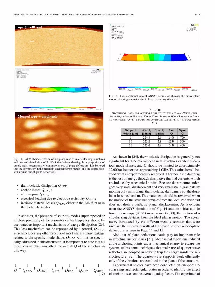
Fig. 14. AFM characterization of out-plane motion in circular ring structuresand cross-sectional view of ANSYS simulations showing the superposition ofpurely radial-extensional vibrations with out-of-plane deflections. It is believedthat the asymmetry in the materials stack (different metals) and the sloped side-walls cause out-of-plane deflections.
• thermoelastic dissipation ;• anchor losses ;• air damping ;• electrical loading due to electrode resistivity ;• intrinsic material losses either in the AlN film or in
the metal electrodes.
In addition, the presence of spurious modes superimposed orin close proximity of the resonator center frequency should beaccounted as important mechanisms of energy dissipation [29].This loss mechanism can be represented by a general, ,which includes any other process of mechanical energy leakagerelated to the specific mode shape. will not be specifi-cally addressed in this discussion. It is important to note that allthese loss mechanisms affect the overall Q of the structure inthis way
(17)
Fig. 15. Cross-sectional view of ANSYS simulation showing the out-of-planemotion of a ring resonator due to linearly sloping sidewalls.
TABLE IIISTATISTICAL DATA FOR ANCHOR LOSS STUDY FOR A 20-�m-WIDE RING
WITH 90 �m INNER RADIUS. THREE DATA SAMPLES WERE TAKEN FOR EACH
SUPPORT SIZE. “AVE.” STANDS FOR AVERAGE VALUE. “SPAN” IS MAX MINUS
MIN
As shown in [24], thermoelastic dissipation is generally notsignificant for AlN micromechanical structures excited in con-tour mode shapes, and Q should be limited to approximately32 000 at frequencies approaching 1 GHz. This value is well be-yond what is experimentally recorded. Thermoelastic dampingis the loss of energy through dissipative thermal currents, whichare induced by mechanical strains. Because the structure under-goes very small displacement and very small strain gradients bymoving only in its plane, thermoelastic damping is not the dom-inant loss mechanism. This statement should be reviewed whenthe motion of the structure deviates from the ideal behavior anddoes not show a perfectly planar displacement. As is evidentfrom the ANSYS simulation of Fig. 14 and the initial atomicforce microscopy (AFM) measurements [30], the motion of acircular ring deviates from the ideal planar motion. The asym-metry introduced by the different metal electrodes that wereused and the sloped sidewalls of the device produce out-of-planedeflections as seen in Figs. 14 and 15.
Also, out-of-plane deflections could play an important rolein affecting anchor losses [31]. Mechanical vibrations inducedat the anchoring points cause mechanical energy to escape thesystem, unless some techniques that make use of quarter-wavereflectors are adopted in order to trap the energy inside the mi-crostructure [32]. The quarter-wave supports work efficientlyonly if the vibrations are confined in the plane of the structure.
Experimental studies have been conducted on one-port cir-cular rings and rectangular plates in order to identify the effectof anchor losses on the overall quality factor. The experimental
1416 JOURNAL OF MICROELECTROMECHANICAL SYSTEMS, VOL. 15, NO. 6, DECEMBER 2006
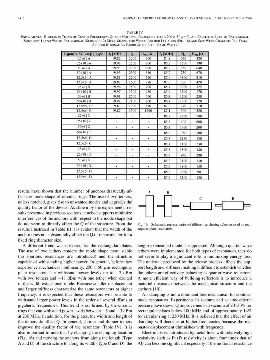
TABLE IVEXPERIMENTAL RESULTS IN TERMS OF CENTER FREQUENCY, Q, AND MOTIONAL RESISTANCE FOR A 200� 50 �m PLATE EXCITED IN LENGTH-EXTENSIONAL
(SUBSCRIPT 1) AND WIDTH-EXTENSIONAL (SUBSCRIPT 2) MODE SHAPES FOR WHICH ANCHOR LOCATION (FIG. 16) AND SIZE WERE CHANGED. THE DATA
ARE FOR RESONATORS FABRICATED ON THE SAME WAFER
results have shown that the number of anchors drastically af-fect the mode shape of circular rings. The use of two tethers,unless notched, gives rise to unwanted modes and degrades thequality factor of the device. As shown by the experimental re-sults presented in previous sections, notched supports minimizeinterferences of the anchors with respect to the mode shape butdo not seem to directly affect the Q of the structure. From theresults illustrated in Table III it is evident that the width of theanchor does not substantially affect the Q of the resonator for afixed ring diameter size.
A different trend was observed for the rectangular plates.The use of two tethers renders the mode shape more stable(no spurious resonances are introduced) and the structurecapable of withstanding higher power. In general, before theyexperience mechanical nonlinearity, 200 50 m rectangularplate resonators can withstand power levels up to 7 dBmwith two tethers and 11 dBm with one tether when excitedin the width-extensional mode. Because smaller displacementand larger stiffness characterize the same resonators at higherfrequency, it is expected that these resonators will be able towithstand larger power levels in the order of several dBms atgigahertz frequencies. This trend is confirmed by the circularrings that can withstand power levels between 5 and 3 dBmat 230 MHz. In addition, for the plates, the width and length ofthe tethers do affect Q. In general, shorter and thinner tethersimprove the quality factor of the resonator (Table IV). It isalso important to note that by changing the clamping location(Fig. 16) and moving the anchors from along the length (TypeA and B) of the structure to along its width (Type C and D), the
Fig. 16. Schematic representation of different anchoring schemes used on rect-angular plate resonators.
length-extensional mode is suppressed. Although quarter-wavetethers were implemented for both types of resonators, they donot seem to play a significant role in minimizing energy loss.The undercut produced by the release process affects the sup-port length and stiffness, making it difficult to establish whetherthe tethers are effectively behaving as quarter-wave reflectors.A more efficient way of building reflectors is to introduce amaterial mismatch between the mechanical structure and theanchors [10].
Air damping is not a dominant loss mechanism for contour-mode resonators. Experiments in vacuum and at atmosphericpressure have shown Q improvements in vacuum of 20–30% forrectangular plates below 100 MHz and of approximately 14%for circular ring at 230 MHz. It is believed that the effect of airdamping will decrease at higher frequencies because the res-onator displacement diminishes with frequency.
Electric losses introduced by metal lines with relatively highresistivity such as Pt (Pt resistivity is about four times that ofAl) can become significant especially if the motional resistance
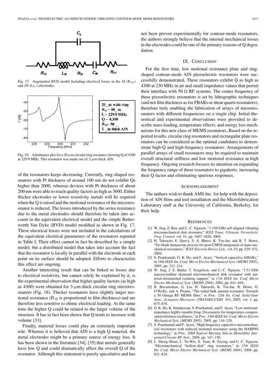
Fig. 17. Augmented BVD model including electrical losses in the Al (R )and (Pt R ) electrodes.
Fig. 18. Admittance plot for a 20�m circular ring resonator showing Q of 4300at 229.9 MHz. This resonator was made out of 3-�m-thick AlN.
of the resonators keeps decreasing. Currently, ring-shaped res-onators with Pt thickness of around 100 nm do not exhibit Qshigher than 2000, whereas devices with Pt thickness of about200 nm were able to reach quality factors as high as 3000. Eitherthicker electrodes or lower resistivity metals will be requiredwhen the Q is raised and the motional resistance of the microres-onator is reduced. The losses introduced by the series resistancedue to the metal electrodes should therefore be taken into ac-count in the equivalent electrical model and the simple Butter-worth Van Dyke (BVD) model modified as shown in Fig. 17.These electrical losses were not included in the calculations ofthe equivalent electrical parameters of the resonators reportedin Table I. Their effect cannot in fact be described by a simplemodel, but a distributed model that takes into account the factthat the resonator is locally in parallel with the electrode at eachpoint on its surface should be adopted. Efforts to characterizethis effect are ongoing.
Another interesting result that can be linked to losses dueto electrical resistivity, but cannot solely be explained by it, isthe experimental observation that higher quality factors (as highas 4300) were obtained for 3- m-thick circular ring microres-onators (Fig. 18). Thicker resonators have slightly larger mo-tional resistance ( is proportional to film thickness) and aretherefore less sensitive to ohmic electrical loading. At the sametime the higher Q could be related to the larger volume of thestructure. It has in fact been shown that Q tends to increase withvolume [33].
Finally, material losses could play an extremely importantrole. Whereas it is believed that AlN is a high Q material, themetal electrodes might be a primary source of energy loss. Ithas been shown in the literature [34], [35] that metals generallyhave low Q and could dramatically affect the overall Q of theresonator. Although this statement is purely speculative and has
not been proven experimentally for contour-mode resonators,the authors strongly believe that the internal mechanical lossesin the electrodes could be one of the primary reasons of Q degra-dation.
IX. CONCLUSION
For the first time, low motional resistance plate and ring-shaped contour-mode AlN piezoelectric resonators were suc-cessfully demonstrated. These resonators exhibit Q as high as4300 at 230 MHz in air and small impedance values that permittheir interface with 50 RF systems. The center frequency ofthese piezoelectric resonators is set by lithographic techniques(and not film thickness as for FBARs or shear quartz resonators),therefore truly enabling the fabrication of arrays of microres-onators with different frequencies on a single chip. Initial the-oretical and experimental observations were provided to de-scribe mass loading, temperature effects, and energy loss mech-anisms for this new class of MEMS resonators. Based on the re-ported results, circular ring resonators and rectangular plate res-onators can be considered as the optimal candidates to demon-strate high-Q and high-frequency resonators. Arrangements ofparallel arrays of small resonators may be required to maintainoverall structural stiffness and low motional resistance at highfrequency. Ongoing research focuses its attention on expandingthe frequency range of these resonators to gigahertz, increasingtheir Q factor and eliminating spurious responses.
ACKNOWLEDGMENT
The authors wish to thank AMS Inc. for help with the deposi-tion of AlN films and tool installation and the MicrofabricationLaboratory staff at the University of California, Berkeley, fortheir help.
REFERENCES
[1] W. Jing, Z. Ren, and C.-C. Nguyen, “1.156-GHz self-aligned vibratingmicromechanical disk resonator,” IEEE Trans. Ultrason. Ferroelectr.Freq. Control, vol. 51, pp. 1607–1628, 2004.
[2] H. Takeuchi, E. Quevy, S. A. Bhave, K. Tsu-Jae, and R. T. Howe,“Ge-blade damascene process for post-CMOS integration of nano-me-chanical resonators,” IEEE Electron Device Lett., vol. 25, pp. 529–531,2004.
[3] S. Pourkamali, G. K. Ho, and F. Ayazi, “Vertical capacitive SiBARs,”in 18th IEEE Int. Conf. Micro Electro Mechanical Syst. (MEMS 2005),2005, pp. 211–214.
[4] W. Jing, J. E. Butler, T. Feygelson, and C.-C. Nguyen, “1.51-GHznanocrystalline diamond micromechanical disk resonator with ma-terial-mismatched isolating support,” in 17th IEEE Int. Conf. MicroElectro Mechanical Syst. (MEMS 2004), 2004, pp. 641–644.
[5] B. Bircumshaw, G. Liu, H. Takeuchi, K. Tsu-Jae, R. Howe, O.O’Reilly, and A. Pisano, “The radial bulk annular resonator: Towardsa 50 Omega RF MEMS filter,” in Proc. 12th Int. Conf. Solid-StateSens., Actuators Microsyst. (TRANSDUCERS ’03), 2003, vol. 1, pp.875–878.
[6] G. K. Ho, K. Sundaresan, S. Pourkamali, and F. Ayazi, “Low-motional-impedance highly-tunable I/sup 2/resonators for temperature-compen-sated reference oscillators,” in Proc. 18th IEEE Int. Conf. Micro ElectroMechanical Syst. (MEMS 2005), 2005, pp. 116–120.
[7] S. Pourkamali and F. Ayazi, “High frequency capacitive micromechan-ical resonators with reduced motional resistance using the HARPSStechnology,” in Proc. 2004 Topical Meeting Silicon Monolithic Inte-grated Circuits RF Syst., 2004, pp. 147–150.
[8] L. Sheng-Shian, L. Yu-Wei, X. Yuan, R. Zeying, and C.-C. Nguyen,“Micromechanical “hollow-disk” ring resonators,” in 17th IEEEInt. Conf. Micro Electro Mechanical Syst. (MEMS 2004), 2004, pp.821–824.
1418 JOURNAL OF MICROELECTROMECHANICAL SYSTEMS, VOL. 15, NO. 6, DECEMBER 2006
[9] S. A. Bhave and R. T. Howe, “Internal electrostatic transduction forbulk MEMS resonators,” in Proc. 2004 Solid State Sens., Actuator Mi-crosyst. Workshop, Hilton Head Island, SC, 2004, pp. 59–60.
[10] ——, “Silicon nitride-on-silicon bar resonator using internal electro-static transduction,” in Proc. Solid-State Sens., Actuators Microsyst.(TRANSDUCERS ’05), 2005, pp. 2139–2142.
[11] D. Penunuri and K. M. Lakin, “RF filter design using LTCC and thinfilm BAW technology,” in Proc. 2001 IEEE Ultrason. Symp., 2001, vol.1, pp. 273–278.
[12] R. Ruby, P. Bradley, J. D. Larson, III, and Y. Oshmyansky, “PCS 1900MHz duplexer using thin film bulk acoustic resonators (FBARs),” Elec-tron. Lett., vol. 35, pp. 794–795, 1999.
[13] F. P. S. D. T. Chang, D. J. Kirby, R. J. Joyce, T.-Y. Hsu, and R. L.Kubena, “A new MEMS-based quartz resonator technology,” in Proc.Solid State Sens., Actuator Microsyst. Workshop, Hilton Head Island,SC, 2004, pp. 41–44.
[14] R. A. Johnson, Mechanical Filters in Electronics. New York: Wiley,1983.
[15] R. Holland, “Contour extensional resonant properties of rectangularpiezoelectric plates,” IEEE Trans. Sonics Ultrason., vol. SU-15, pp.97–105, 1968.
[16] M. Onoe, “Contour vibrations of thin rectangular plates,” J. Acoust.Soc. Amer., vol. 30, pp. 1159–1162, 1958.
[17] G. Ambati, J. F. W. Bell, and J. C. K. Sharp, “In-plane vibrations ofannular rings,” J. Sound Vibrations, vol. 47, pp. 415–432, 1976.
[18] K. F. Graff, Wave Motion in Elastic Solids. New York: Dover, 1991.[19] G. Piazza, P. J. Stephanou, M. B. J. Wijesundara, and A. P. Pisano,
“Single-chip multiple-frequency filters based on contour-mode alu-minum nitride piezoelectric micromechanical resonators,” in Proc.Solid-State Sens., Actuators Microsyst. (TRANSDUCERS ’05), 2005,pp. 2065–2068.
[20] E. P. Quevy and R. T. Howe, “Redundant MEMS resonators for pre-cise reference oscillators,” in Proc. Radio Frequency Integrated Cir-cuits (RFIC) Symp., 2005, pp. 113–116.
[21] G. Bu, D. Ciplys, M. Shur, L. J. Schowalter, S. Schujman, and R.Gaska, “Temperature coefficient of SAW frequency in single crystalbulk AlN,” Electron. Lett., pp. 755–757, 2003.
[22] P. Wei, Y. Hongyu, Z. Hao, and E. S. Kim, “Temperature-compensatedfilm bulk acoustic resonator above 2 GHz,” IEEE Electron Device Lett.,pp. 369–371, 2005.
[23] H. Wan-Thai, J. R. Clark, and C.-C. Nguyen, “Mechanically temper-ature-compensated flexural-mode micromechanical resonators,” inProc. Int. Electron Devices Meeting (IEDM 2000), 2000, pp. 399–402.
[24] B. Antkowiak, J. P. Gorman, M. Varghese, D. J. D. Carter, and A. E.Duwel, “Design of a high-Q, low-impedance, GHz-range piezoelectricmems resonator,” in Proc. 12th Int. Conf. Solid-State Sens., ActuatorsMicrosyst. (TRANSDUCERS ’03), 2003, vol. 1, pp. 841–846.
[25] R. Abdolvand, G. K. Ho, A. Erbil, and F. Ayazi, “Thermoelasticdamping in trench-refilled polysilicon resonators,” in Proc. 12th Int.Conf. Solid-State Sens., Actuators Microsyst. (TRANSDUCERS ’03),2003, vol. 1, pp. 324–327.
[26] R. N. Candler, H. Li, M. Lutz, W. T. Park, A. Partridge, G. Yama, and T.W. Kenny, “Investigation of energy loss mechanisms in micromechan-ical resonators,” in Proc. 12th Int. Conf. Solid-State Sens., ActuatorsMicrosyst. (TRANSDUCERS ’03), 2003, vol. 1, pp. 332–335.
[27] V. T. Srikar and S. D. Senturia, “Thermoelastic damping infine-grained polysilicon flexural beam resonators,” J. Microelec-tromech. Syst., pp. 499–504, 2002.
[28] X. M. H. Huang, C. A. Zorman, M. Mehregany, and M. L. Roukes,“Quality factor issues in silicon carbide nanomechanical resonators,” inProc. 12th Int. Conf. Solid-State Sens., Actuators Microsyst. (TRANS-DUCERS ’03), 2003, vol. 1, pp. 722–725.
[29] R. C. Ruby, J. D. Larson, R. S. Fazzio, and C. Feng, “Performancedegradation effects in FBAR filters and resonators due to lamb wavemodes,” in 2005 IEEE Ultrason. Symp., 2005, pp. 1832–1835.
[30] X. Liu, A. San Paulo, M. Park, and J. Bokor, “Characterization ofacoustic vibration modes at GHz frequencies in bulk acoustic wave res-onators by combination of scanning laser interferometry and scanningacoustic force microscopy,” in Proc. 18th IEEE Int. Conf. Micro ElectroMechanical Syst. (MEMS 2005), 2005, pp. 175–178.
[31] D. S. Binder, E. Quevy, T. Koyama, S. Govindjee, J. W. Demmel, andR. T. Howe, “Anchor loss simulation in resonators,” in Proc. 18th IEEEInt. Conf. Micro Electro Mechanical Syst. (MEMS 2005), 2005, pp.133–136.
[32] K. M. Lakin, K. T. McCarron, and R. E. Rose, “Solidly mounted res-onators and filters,” in Proc. 1995 IEEE Ultrason. Symp., 1995, vol. 2,pp. 905–908.
[33] K. L. Ekinci and M. L. Roukes, “Nanoelectromechanical systems,”Rev. Sci. Instrum., vol. 76, pp. 61101-1–61101-12, 2005.
[34] R. Lanz, M. A. Dubois, and P. Muralt, “Solidly mounted BAW filtersfor the 6 to 8 GHz range based on AlN,” in 2001 IEEE Ultrason. Symp.,2001, vol. 1, pp. 843–846.
[35] C. G. Courcimault and M. G. Allen, “High-Q mechanical tuning ofMEMS resonators using a metal deposition—annealing technique,” inProc. Solid-State Sens., Actuators Microsyst. (TRANSDUCERS ’05),2005, pp. 875–878.
[36] P. J. Stephanou, G. Piazza, C. D. White, M. B. J. Wijesundara, andA. P. Pisano, “Piezoelectric thin film AlN annular dual contour modebandpass filter,” in Proc. ASME IMECE 2005, 2005.
Gianluca Piazza (S’00–M’06) received the Ph.D. degree from the Universityof California, Berkeley, in 2005.
He is an Assistant Professor in the Department of Electrical and Systems En-gineering, the University of Pennsylvania, Philadelphia. His research interestsfocus on piezoelectric micro and nano systems (MEMS/NEMS) for RF wire-less communications, biological detection, and wireless sensor platforms. Healso has general interest in the areas of micro/nanofabrication techniques andintegration of micro/nanodevices with state-of-the-art electronics. He developeda new class of AlN contour-mode vibrating microstructures for RF communi-cations. He has more than six years of experience working with piezoelectricmaterials, has received two patents in the field of micromechanical resonators,and cofounded a startup company (Harmonic Devices, Inc.) for the commercial-ization of piezoelectric resonators.
Philip J. Stephanou (M’05) received the B.S. and M.S. degrees from Rensse-laer Polytechnic Institute, Troy, NY, in 2001 and 2002, respectively. He is cur-rently pursuing the Ph.D. degree at the Mechanical Engineering Department,University of California, Berkeley.
His thesis investigated the performance of novel algorithms for computationalmulti-rigid-body dynamics. His current research involves the analysis, designand fabrication of piezoelectric RF MEMS resonators and filters for highly in-tegrated communication systems. In spring 2005, he cofounded Harmonic De-vices, Inc., a fabless semiconductor startup company committed to commercial-izing research breakthroughs in the area of RF MEMS for the mobile handsetmarket. He is currently the acting Chief Technology Officer.
Albert (“Al”) P. Pisano received the B.S., M.S., and Ph.D. degrees in mechan-ical engineering from Columbia University, New York, NY.
He currently is Professor and Chair of the Department of Mechanical Engi-neering, University of California (UC), Berkeley, where he holds the FANUCChair of Mechanical Systems in the Department of Mechanical Engineering,with a joint appointment to the Department of Electrical Engineering and Com-puter Science. He currently is a Director of the Berkeley Sensor and ActuatorCenter (BSAC). Prior to joining UC Berkeley, he held research positions withXerox Palo Alto Research Center, Singer Sewing Machines Corporate R&DCenter, and General Motors Research Labs. From 1997 to 1999, he was ProgramManager for the MEMS program at the Defense Advanced Research ProjectsAgency. His research interests and activities at UC Berkeley include MEMSfor a wide variety of applications, including RF components, power generation,drug delivery, strain sensors, biosensors and disk-drive actuators. He is the Coin-ventor listed on 20 patents in MEMS. He has authored or coauthored more than190 archival publications. He is a Cofounder of startup companies in the areaof transdermal drug delivery, transvascular drug delivery, sensorized catheters,MEMS manufacturing equipment, and MEMS RF devices.
Prof. Pisano was elected to the National Academy of Engineering in 2001.