Horizontal Tubular Bioreactors in Biotechnology B. Šantek, * M. Ivanèiæ, P. Horvat, S. Novak, and V. Mariæ Department of Biochemical Engineering, Faculty of Food Technology and Biotechnology, University of Zagreb, Pierottijeva 6/IV, Zagreb, HR-10 000 Zagreb, Croatia In this review, horizontal tubular bioreactors are discussed regarding their advan- tages and disadvantages compared to other bioreactor types. In horizontal tubular bioreactors medium flow is characterized by plug flow conditions that can be favorable in the case of inhibition and/or repression bioprocess kinetics. For description of liquid flow simple one-parameter or complex multi-parameters mathematical models have been established. Comparison between these models proved that complex multi-parameters model can describe real situation in the bioreactor more efficiently. Criteria of geometri- cal similarity are most often used for scale-up of horizontal tubular bioreactors. The suc- cessful scale-up procedure should combine the mathematical model of medium flow be- havior with bioprocess kinetics in the bioreactor. Key words: Horizontal tubular bioreactors, mixing, mathematical modeling, bioprocess kinetics, scale-up Introduction In biotechnology different bioreactors are used to conduct different bioprocesses regarding bioprocess kinetics, hydrodynamics and scale of operation. Stirred tank bioreactors have been used most often due to their suitability for conduction of different bioprocesses. However, they have also some disadvantages, such as problems with bear- ings and sealing, cell damage, high power con- sumption and high costs of cooling. 1 For these rea- sons new bioreactor types (e.g. air lift, jet or tubular bioreactors) were developed to solve these prob- lems. In two stage bioprocesses, stirred tank bio- reactors can be used in combination with other bioreactor types (e.g. tubular bioreactors). In this situation, biomass cultivation is carried out in a stirred tank bioreactor (first step) and production of metabolites or bioconversion processes take place in tubular bioreactor (second step), respectively. A typical example for such combination is biopesti- cides production. 2,3 Tubular bioreactors, either ver- tical or horizontal, have some potential advantages over stirred tank bioreactors. 4,5 They have usually simple construction and possibility to prepare dif- ferent inner configurations by the use of standard industrial support materials. For construction of tu- bular bioreactors and their scale-up it is necessary to know less number of parameters than for the stirred tank bioreactors where type and number of impellers, distance between impellers, type and number of impeller blades, type and size of power input has to be known. Mixing in tubular bio- reactors is more uniform compared to the stirred tank bioreactors. Thus, it is easier to eliminate “dead” zones that make the scale-up procedure more reli- able. Area-to-volume ratio is significantly higher in tubular bioreactors resulting in more efficient mass and heat transfer processes. This is particularly im- portant in bioprocesses with semi-solid or solid substrates, photoreactions (maximum exposure to light) and shear sensitive organisms etc. Due to the plug flow conditions the gradients of concentrations along the bioreactor length are established that is advantage in the case of inhibition and/or repres- sion bioprocess kinetics. In these cases, high pro- ductivity and optimal conversion are achieved si- multaneously during cultivation. Tubular bio- reactors are easy to maintain due to the fact that their basic elements are widely used in bioprocess industry (pipes, pumps, standard fittings). There are some substantial differences between horizontal and vertical tubular bioreactors (tubular and tower bioreactors). In industrial tower bioreactors very of- ten the superficial gas velocity and the power input required for compression of the feed gas to overco- me the high static liquid pressure tend to be unallowably high. In tubular bioreactors plug flow is not disturbed by the bioprocess gasses and the hydrostatic pressure can not have inhibiting effect or create practical problems. Although tubular bio- reactors have great potentials for use in biotechnol- ogy they have also some disadvantages compared to the stirred tank bioreactors. Tubular bioreactors B. ŠANTEK et al., Horizontal Tubular Bioreactors in Biotechnology, Chem. Biochem. Eng. Q. 20 (4) 389–399 (2006) 389 * Corresponding author: e-mail: [email protected], tel. **385–1–4605142, fax **385–1–4836424 Original scientific paper Received: July 18, 2006 Accepted: October 10, 2006
Transcript
Horizontal Tubular Bioreactors in Biotechnology
B. Šantek,* M. Ivanèiæ, P. Horvat, S. Novak, and V. MariæDepartment of Biochemical Engineering, Faculty of Food Technologyand Biotechnology, University of Zagreb, Pierottijeva 6/IV, Zagreb,HR-10 000 Zagreb, Croatia
In this review, horizontal tubular bioreactors are discussed regarding their advan-tages and disadvantages compared to other bioreactor types. In horizontal tubularbioreactors medium flow is characterized by plug flow conditions that can be favorablein the case of inhibition and/or repression bioprocess kinetics. For description of liquidflow simple one-parameter or complex multi-parameters mathematical models have beenestablished. Comparison between these models proved that complex multi-parametersmodel can describe real situation in the bioreactor more efficiently. Criteria of geometri-cal similarity are most often used for scale-up of horizontal tubular bioreactors. The suc-cessful scale-up procedure should combine the mathematical model of medium flow be-havior with bioprocess kinetics in the bioreactor.
In biotechnology different bioreactors are usedto conduct different bioprocesses regardingbioprocess kinetics, hydrodynamics and scale ofoperation. Stirred tank bioreactors have been usedmost often due to their suitability for conduction ofdifferent bioprocesses. However, they have alsosome disadvantages, such as problems with bear-ings and sealing, cell damage, high power con-sumption and high costs of cooling.1 For these rea-sons new bioreactor types (e.g. air lift, jet or tubularbioreactors) were developed to solve these prob-lems. In two stage bioprocesses, stirred tank bio-reactors can be used in combination with otherbioreactor types (e.g. tubular bioreactors). In thissituation, biomass cultivation is carried out in astirred tank bioreactor (first step) and production ofmetabolites or bioconversion processes take placein tubular bioreactor (second step), respectively. Atypical example for such combination is biopesti-cides production.2,3 Tubular bioreactors, either ver-tical or horizontal, have some potential advantagesover stirred tank bioreactors.4,5 They have usuallysimple construction and possibility to prepare dif-ferent inner configurations by the use of standardindustrial support materials. For construction of tu-bular bioreactors and their scale-up it is necessaryto know less number of parameters than for thestirred tank bioreactors where type and number ofimpellers, distance between impellers, type and
number of impeller blades, type and size of powerinput has to be known. Mixing in tubular bio-reactors is more uniform compared to the stirredtank bioreactors. Thus, it is easier to eliminate “dead”zones that make the scale-up procedure more reli-able. Area-to-volume ratio is significantly higher intubular bioreactors resulting in more efficient massand heat transfer processes. This is particularly im-portant in bioprocesses with semi-solid or solidsubstrates, photoreactions (maximum exposure tolight) and shear sensitive organisms etc. Due to theplug flow conditions the gradients of concentrationsalong the bioreactor length are established that isadvantage in the case of inhibition and/or repres-sion bioprocess kinetics. In these cases, high pro-ductivity and optimal conversion are achieved si-multaneously during cultivation. Tubular bio-reactors are easy to maintain due to the fact thattheir basic elements are widely used in bioprocessindustry (pipes, pumps, standard fittings). There aresome substantial differences between horizontaland vertical tubular bioreactors (tubular and towerbioreactors). In industrial tower bioreactors very of-ten the superficial gas velocity and the power inputrequired for compression of the feed gas to overco-me the high static liquid pressure tend to beunallowably high. In tubular bioreactors plug flowis not disturbed by the bioprocess gasses and thehydrostatic pressure can not have inhibiting effector create practical problems. Although tubular bio-reactors have great potentials for use in biotechnol-ogy they have also some disadvantages comparedto the stirred tank bioreactors. Tubular bioreactors
B. ŠANTEK et al., Horizontal Tubular Bioreactors in Biotechnology, Chem. Biochem. Eng. Q. 20 (4) 389–399 (2006) 389
are suitable for continuous mode of operation, butin industry most bioprocesses are still run in batchmode. Another disadvantage is a relatively low oxy-gen supply capacity, what makes them unsuitablefor conduction of bioprocesses with high oxygendemand (e.g. biomass and acetic acid production).
During conduction of bioprocess in tubularbioreactors microbial biofilm is very often formedon the inner surface of bioreactors which addition-ally increases bioprocess efficiency and stabilitycompared to the bioreactors with suspended micro-bial cells. In tubular bioreactors with microbialbiofilm biomass washout can happen very rarely al-though relatively high inflow rates are used. Majordisadvantage of a tubular bioreactor with microbialbiofilm is the problem of mass transfer inside themicrobial biofilm. This effect usually happens inthicker biofilms where substrate and oxygen limita-tions are very often present, thus resulting in loss ofcell viability. In these conditions, biofilm erosionand sloughing processes6,7 tend to occur, thus sub-stantially disturbing the bioreactor performance.This problem can be solved by the control ofbiofilm thickness which can be based on mechani-cal scraping or abrasion by friction (the self-regula-tion effect at high hydrodynamic stress). On theother hand, thicker microbial biofilm, in somecases, can be advantageous. In case of substrate in-hibition the most favorable substrate concentrationsare inside the microbial biofilm where bio-conversion rate is optimal for bioprocess conduc-tion. In mixed microbial culture different speciesgrow along the depth of biofilm, for example inwastewater treatment processes the nitrifiers grownear the surface and denitrifiers in the inner biofilmlayers which are favorable conditions for the pro-cess of simultaneous nitrification and denitrifi-cation.4 Growth of microbial biofilm on the innersurface of tubular photobioreactors is not favorabledue to the fact that it can reduce the amount of lightavailable to the phototrophic cells. On the basis ofprevious consideration it is clear that tubularbioreactors have great potential for conduction ofdifferent bioprocesses and therefore they must beused in biotechnology more often.
Bioreactor types and areasof application
In chemical engineering horizontal reactors arewell known e.g. rotary drum reactors, rotating cyl-inders, pipeline contactors and rotary kilns. Thesereactor constructions have positive effects on theprocesses inside reactors such as e.g. mixing, heatand mass transfer.8–10 In our further considerationhorizontal tubular bioreactors developed for use in
fermentation and wastewater treatment processes,semi-solid or solid state and phototrophic biopro-cesses as well as in tissue engineering will be con-sidered.
Horizontal tubular bioreactors in fermentationand wastewater treatment processes
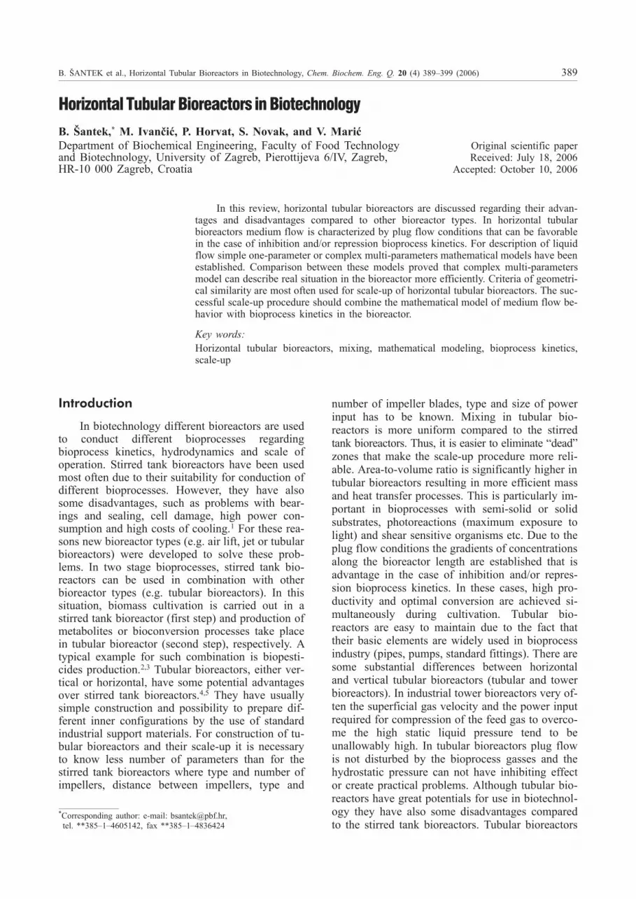
Different constructions of horizontal tubularbioreactors developed for fermentation and waste-water treatment processes are presented in Fig. 1.The simplest construction of horizontal tubularbioreactor (Fig. 1a) is a straight or a spiral tubemade to mimic natural flow in the rivers or in thelong open channels. This bioreactor construction isvery often used in wastewater treatment processes.Another common use of this bioreactor construc-tion is in sterilization technology as a holding sec-tion.4 Biodisc reactor as a horizontal bioreactor hasbeen developed for wastewater treatment11 (Fig.1b). It consists of a series of closely spaced discsfixed to a rotating shaft. The discs are usually madeof plastic material (polyethylene, PVC, expanded
390 B. ŠANTEK et al., Horizontal Tubular Bioreactors in Biotechnology, Chem. Biochem. Eng. Q. 20 (4) 389–399 (2006)
F i g . 1 – Horizontal tubular bioreactors: a) simple tube, b)biodisc reactor, c) multiple blade tubular bioreactor (MBTB),d) horizontal rotary bioreactor (HRB), e) thin–layer tubularbioreactor (ThLTB) and mechanically agitated and aerated tu-bular bioreactor (MATB), f) pneumatically aerated and agi-tated tubular bioreactor (PATB), g) mechanically or pneumati-cally scraped tubular bioreactor (MSTB or PSTB)
polystyrene) and about 40 % of their area is sub-mersed in liquid phase. During wastewater treat-ment microbial biofilm is usually formed on the ro-tating discs that are partially submerged intowastewater to absorb substrate and then raised outof the liquid phase to the air in order to oxidize theabsorbed substrate. A similar design is applied inthe multiple blade horizontal bioreactor (MBHB)that was constructed for bioprocesses with mycelialmicroorganisms without the biofilm formation12
(Fig. 1c). The bioreactor consists of several cylin-drical compartments, where each part is sealed offfrom its neighbouring compartment by a separatingplate having an overflow hole in the upper half. Thecombined splashing of the bioreactor walls and theshearing action between the stirrer blades and baf-fles installed vertically at the bottom of each com-partment in the bioreactor increased mixing andsuppressed the formation of biofilm. Similar hori-zontal cylindrical devices with several rotationdiscs are used for conduction of different bio-processes.13 Horizontal rotary bioreactor (HRB) ischaracterized by an un-baffled rotating tube14 (Fig.1d). This bioreactor type was used for conductionof gluconic acid production by Pseudomonasovalis15 and cellulase production by Trichodermasp.16 The thin-layer tubular bioreactor (ThLTB) wasdesigned for verification of Danckwerts renewaltheory of mass transfer17,18 (Fig. 1e). This bio-reactor was used for conduction of bioprocesseswith relatively low foaming intensity.19 In case ofyeast production this bioreactor construction wasmodified by incorporation of baffles on the bio-reactor wall as well as blades on the central rotatingtube in order to increase the oxygen transfer rate.This bioreactor is named the mechanically agitatedand aerated tubular bioreactor19,20 (MATB; Fig.1e).All previously mentioned tubular bioreactors(HRB, ThLTB and MATB) are characterized by arelatively thin liquid layer inside the bioreactorwhich has positive effect on the mixing intensityand mass transfer phenomena.21 The pneumaticallyaerated tubular bioreactor (PATB; Fig. 1f) was de-veloped for aerobic wastewater treatment.19,22 It ischaracterized by the absence of any mechanical de-vice and the air (or O2) is introduced over the entirebioreactor length so that oxygen limitation can beeasily avoided. A complex biokinetics with sub-strate and product inhibition was studied in this bio-reactor during continuous ethanol production withZymomonas mobilis. Also, a biomass maturationconcept of Bacillus thuringiensis was studied in thisbioreactor. In both cases, higher substrate conver-sion coefficients and bioprocess productivities wereobserved compared to the continuous stirred tankbioreactor.2,3 The scraped tubular bioreactors can beagitated mechanically (MSTB) or pneumatically
with gas jets (PSTB). They were designed for theenzyme production e.g. lipase by yeast andcellulase by fungi23 (Fig. 1g). In these bioreactors,microbial wall growth was minimized by using ro-tating internal coils, a moving belt of internal discsor helical ribbons and orifices directly in the tube.These scrapers partially segregate the liquid intomoving compartments, where cross-flow aeration,effected by orifices at the bottom is realized in thesame way as in PATB. In horizontal tubular bio-reactors maintenance of stable suspended biomassconcentration gradient along the bioreactor can be aproblem due to biomass washout. This problem canbe solved by partial recirculation of bioreactor out-flow. The effect of recirculation on the plug flow inthe mechanically agitated tubular bioreactor wasstudied and it was observed that the increase of therecycle ratio was related to the decrease of plugflow conditions.24
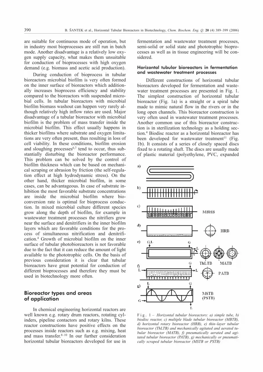
The horizontal rotating tubular bioreactor(HRTB) was designed as a combination of a thinlayer18,20 and a biodisc reactor.11 Its interior is di-vided by O-ring shaped partition walls (distance be-tween the partition walls is 0.02 m) that serve ascarriers for microbial biofilm. The HRTB wasplaced on the bearings that enable rotation of thewhole bioreactor (Fig. 2). The aeration was donethrough the central tube fixed in the axis of HRTB.The aeration tube has five extended tubes that weresubmersed in a liquid phase on five positions alongthe bioreactor to bring the air into culture.25,26
HRTB was tested in anaerobic27,28 and aerobic29
bioprocesses.
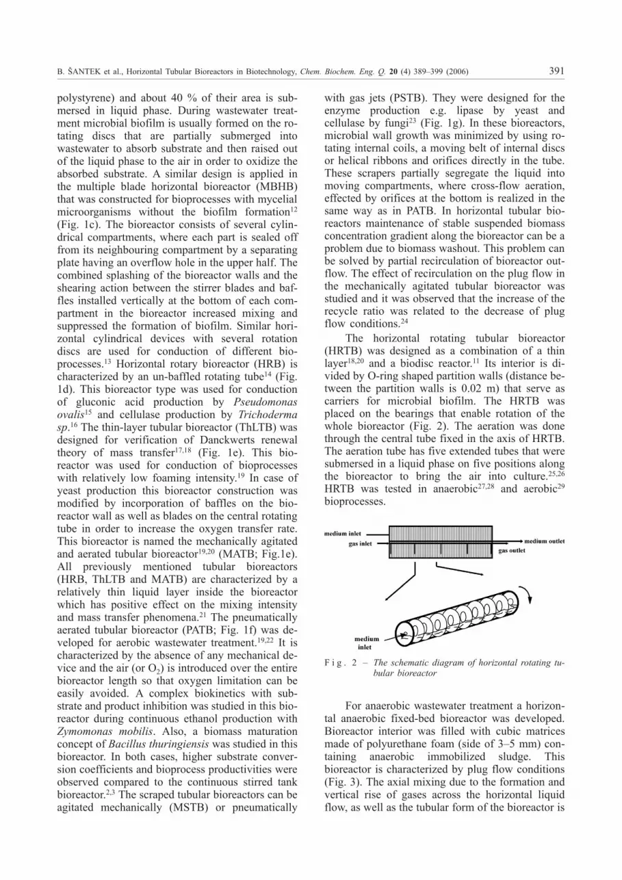
For anaerobic wastewater treatment a horizon-tal anaerobic fixed-bed bioreactor was developed.Bioreactor interior was filled with cubic matricesmade of polyurethane foam (side of 3–5 mm) con-taining anaerobic immobilized sludge. Thisbioreactor is characterized by plug flow conditions(Fig. 3). The axial mixing due to the formation andvertical rise of gases across the horizontal liquidflow, as well as the tubular form of the bioreactor is
B. ŠANTEK et al., Horizontal Tubular Bioreactors in Biotechnology, Chem. Biochem. Eng. Q. 20 (4) 389–399 (2006) 391
F i g . 2 – The schematic diagram of horizontal rotating tu-bular bioreactor
expected to promote a plug flow conditions. Thegas tube collector along the bioreactor permitsminimization of dead volume for gas separation.This bioreactor is also characterized by a relativelyshort start-up period (8 days) for establishment ofstable operating conditions.30,31
Horizontal tubular bioreactors in bioprocesseswith semi-solid or solid substrates
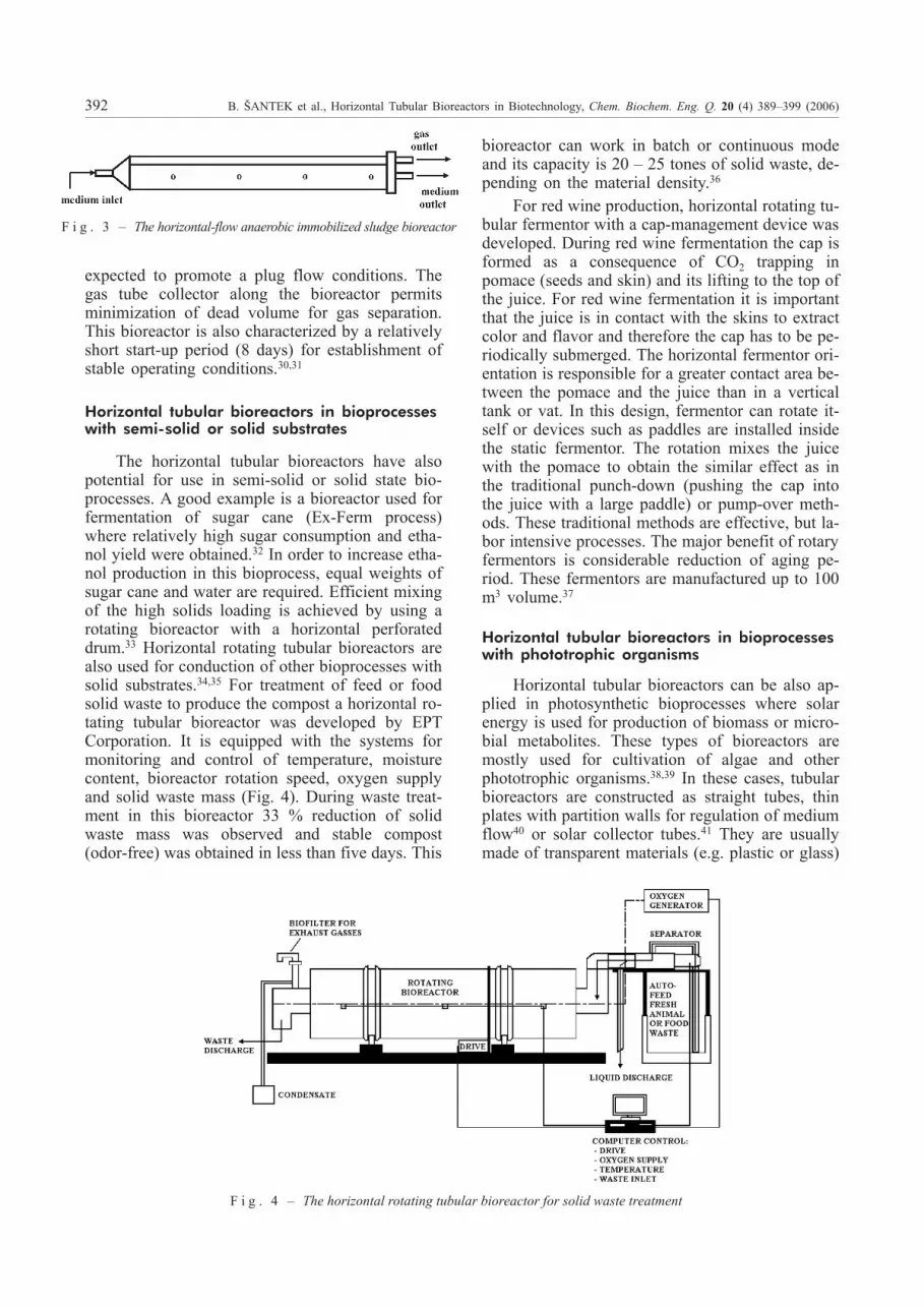
The horizontal tubular bioreactors have alsopotential for use in semi-solid or solid state bio-processes. A good example is a bioreactor used forfermentation of sugar cane (Ex-Ferm process)where relatively high sugar consumption and etha-nol yield were obtained.32 In order to increase etha-nol production in this bioprocess, equal weights ofsugar cane and water are required. Efficient mixingof the high solids loading is achieved by using arotating bioreactor with a horizontal perforateddrum.33 Horizontal rotating tubular bioreactors arealso used for conduction of other bioprocesses withsolid substrates.34,35 For treatment of feed or foodsolid waste to produce the compost a horizontal ro-tating tubular bioreactor was developed by EPTCorporation. It is equipped with the systems formonitoring and control of temperature, moisturecontent, bioreactor rotation speed, oxygen supplyand solid waste mass (Fig. 4). During waste treat-ment in this bioreactor 33 % reduction of solidwaste mass was observed and stable compost(odor-free) was obtained in less than five days. This
bioreactor can work in batch or continuous modeand its capacity is 20 – 25 tones of solid waste, de-pending on the material density.36
For red wine production, horizontal rotating tu-bular fermentor with a cap-management device wasdeveloped. During red wine fermentation the cap isformed as a consequence of CO2 trapping inpomace (seeds and skin) and its lifting to the top ofthe juice. For red wine fermentation it is importantthat the juice is in contact with the skins to extractcolor and flavor and therefore the cap has to be pe-riodically submerged. The horizontal fermentor ori-entation is responsible for a greater contact area be-tween the pomace and the juice than in a verticaltank or vat. In this design, fermentor can rotate it-self or devices such as paddles are installed insidethe static fermentor. The rotation mixes the juicewith the pomace to obtain the similar effect as inthe traditional punch-down (pushing the cap intothe juice with a large paddle) or pump-over meth-ods. These traditional methods are effective, but la-bor intensive processes. The major benefit of rotaryfermentors is considerable reduction of aging pe-riod. These fermentors are manufactured up to 100m3 volume.37
Horizontal tubular bioreactors in bioprocesseswith phototrophic organisms
Horizontal tubular bioreactors can be also ap-plied in photosynthetic bioprocesses where solarenergy is used for production of biomass or micro-bial metabolites. These types of bioreactors aremostly used for cultivation of algae and otherphototrophic organisms.38,39 In these cases, tubularbioreactors are constructed as straight tubes, thinplates with partition walls for regulation of mediumflow40 or solar collector tubes.41 They are usuallymade of transparent materials (e.g. plastic or glass)
392 B. ŠANTEK et al., Horizontal Tubular Bioreactors in Biotechnology, Chem. Biochem. Eng. Q. 20 (4) 389–399 (2006)
F i g . 3 – The horizontal-flow anaerobic immobilized sludge bioreactor
F i g . 4 – The horizontal rotating tubular bioreactor for solid waste treatment
in order to achieve adequate supply of light. Thebasic principle in all of these constructions is to re-duce the light path and thus to increase the amountof light available to cells. These bioreactors arewell mixed to ensure optimum light availability tothe cells and to enhance gas exchange. They arealso characterized by high light utilization effi-ciency, efficient control of cultivation conditionsand ability to operate in continuous mode. Pilotscale units of these bioreactors were used for culti-vation of Spirulina, Chlorella and several marinemicroalgae.42,43 The BIOCOIL is a helical tubularphotobioreactor consisting of a photostage of smalldiameter clear plastic tubing (between 2.4 and 5 cmdiameter) attached helically around a gas exchangetower. Several parallel bands of tubes are connectedto a pumping system.42,43 Pilot scale of this bio-reactor (700 L) was used for cultivation of a widerange of marine microalgae (Tetraselmis spp.,Isochrysis galbana, Phaeodactylum tricornutum,Chaetoceros spp. and Spirulina) for periods greaterthan 4 months in semi-continuous mode. This bio-reactor design ensures uniform mixing and mini-mizes adhesion of the algal cells to the inner bio-reactor surface. The BIOCOIL can also be scaledup easily and the whole bioprocess can be auto-mated thus minimizing labor costs and improvingreliability.43 The largest industrial horizontal tubularbioreactor for cultivation of algae Chlorella wasbuilt up in the year 2000 near Wolfsburg (Ger-many). This bioreactor consists of compact and ver-tically arranged horizontal running glass tubes of atotal length of 500 km and a total volume of700 m3. It is placed in a glasshouse of an area ofonly 10 000 m2 and the annual production of drybiomass is 130–150 tones.44
Horizontal tubular bioreactors in bioprocesseswith biological tissues
In tissue engineering the major problem is howto define the environmental conditions where theoptimal growth of submersed biological tissues canbe achieved. Biological tissues are very sensitive totheir environment and, if exposed to harsh condi-
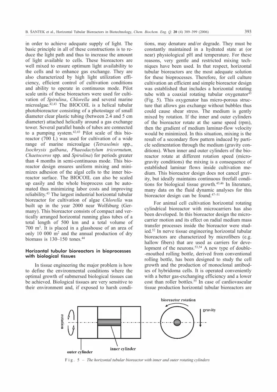
tions, may denature and/or degrade. They must beconstantly maintained in a hydrated state at (ornear) physiological pH and temperature. For thesereasons, very gentle and restricted mixing tech-niques have been used. In that respect, horizontaltubular bioreactors are the most adequate solutionfor these bioprocesses. Therefore, for cell culturecultivation an efficient and simple bioreactor designwas established that includes a horizontal rotatingtube with a coaxial rotating tubular oxygenator45
(Fig. 5). This oxygenator has micro-porous struc-ture that allows gas exchange without bubbles thuscould cause shear stress. The medium is gentlymixed by rotation. If the inner and outer cylindersof the bioreactor rotate at the same speed (rpm),then the gradient of medium laminar-flow velocitywould be minimized. In this situation, mixing is theresult of a secondary flow pattern induced by parti-cle sedimentation through the medium (gravity con-ditions). When inner and outer cylinders of the bio-reactor rotate at different rotation speed (micro-gravity conditions) the mixing is a consequence ofestablished laminar flows inside cultivation me-dium. This bioreactor design does not cancel grav-ity, but ideally maintains continuous freefall condi-tions for biological tissue growth.45,46 In literature,many data on the fluid dynamic analyses for thisbioreactor design can be found.47–51
For animal cell cultivation horizontal rotatingcylindrical bioreactor with microcarriers has alsobeen developed. In this bioreactor design the micro-carrier motion and its effect on radial medium masstransfer processes inside the bioreactor were stud-ied.52 In nerve tissue engineering horizontal tubularbioreactors are characterized by microfibers (e.g.hallow fibers) that are used as carriers for deve-lopment of the neurons.53,54 A new type of double--mouthed rolling bottle, derived from conventionalrolling bottle, has been designed to study the cellgrowth and the production of monoclonal antibod-ies of hybridoma cells. It is operated convenientlywith a better gas-exchanging efficiency and a lowercost than roller bottles.55 In case of cardiovasculartissue production horizontal tubular bioreactors are
B. ŠANTEK et al., Horizontal Tubular Bioreactors in Biotechnology, Chem. Biochem. Eng. Q. 20 (4) 389–399 (2006) 393
F i g . 5 – The horizontal tubular bioreactor with inner and outer rotating cylinders
also used providing reproducible results for specificbiomechanical and biochemical parameters thatplay an important role in tissue engineering. Basedon these results, a new bioreactor designs for car-diovascular tissue engineering were made withbetter mechanical properties and morphologicalcharacteristics compared to the static cultivation.56
Mathematical modeling and scale-up
For successful construction of horizontal tubu-lar bioreactors, their hydrodynamic characterizationand scale-up many variables should be known: mix-ing (flow) and mass transfer characteristics, profilesof substrate concentration, mixing time as well asdistribution of residence and circulation times. Res-idence and circulation time distributions are ob-tained by measuring the system response on thepulse or step change in the bioreactor inflow. Math-ematical models of mixing coupled with bioprocesskinetic model and computational fluid dynamics arenecessary for the successful bioreactor construc-tion.
Mixing and bioprocess kinetics
Characteristics of liquid flow in horizontaltubular bioreactors are possible to describe byone-parameter (dispersion and cascade model) andmulti-parameters mathematical models.57 One-pa-rameter axial dispersion model is the most oftenused model for mixing (or flow) characterization inhorizontal tubular bioreactors and it is based on themass balance of medium component (ci) in the liq-uid phase of the bioreactor. The model is defined bythe following equation:
�
�
�
�
�
�
c
tD
c
zv
ci
zi i� z z
2
2 (1)
The equation 1 is also very often expressed indimensionless form with Bodenstein (Bo) numberas a parameter. This equation could not be solvedanalytically when the change of liquid flow behav-ior (ideal mixing flow into plug flow or reverse) oc-curs in the point of pulse introduction and in themeasuring point. In this situation, equation 1 couldbe only solved numerically. In axial dispersionmodel radial flow of liquid phase in bioreactor isneglected.
The cascade (tank in series) model can be alsoused for mixing (or flow) characterization in hori-zontal tubular bioreactors. The liquid flow inbioreactor can be simulated by the series of ideallymixed cascades (N) and the number of cascades isthe variable parameter of this model. The model isdefined by the following equation:
CN N
Ne
NN
���
�
( )
( )!
1
1(2)
The plug flow conditions are present in hori-zontal tubular bioreactors when N � 5 (or Bo � 7),while ideal mixed flow behavior is realized whenN = 1. When moving parts are incorporated in ho-rizontal tubular bioreactors (rotating inner tubewith or without blades) one-parameter mixing mod-els could not successfully describe flow behavior.Therefore multi-parameters models were estab-lished for mixing characterization in these bio-reactors. In real horizontal tubular bioreactors axialand radial mixing are present and therefore two-pa-rameters dispersion model was established:24
�
�
�
�
�
�
�
�
�
�
c
tv
c
zD
c
zD
R RR
c
Ri i i i�
�
��
�
��
z z R
2
2
1(3)
For thin layer tubular bioreactors mass transfer(e.g., oxygen) can be defined by followingmulti-parameters dispersion model that definesmixing and oxygen transfer.18
�
�
�
�
�
�
�
�
c
tD
c
Rv
c
Rv
c
zr ci i i i
in� O R z A2
2
2
*
(4)
In real horizontal tubular bioreactor with devel-oped microbial biofilm on the inner surface of thebioreactor the bioprocess kinetics in steady stateconditions could be described by the use of Monodmodel and the mass balance of the system:
QA A
Y KzL S
M X S FX F F
X S S Sd d
# $
�
/ ( )0 (5)
When substrate saturation constant (KS) andbiofilm thickness (F) are constant (boundary con-ditions z = 0, �S = �S0 and z = z, �S = �S) solution ofequation 5 is:24
ln/
# $ S
S
S S
S
M F X
X S
FX F
L S0
0�
�
���
�
���K Y
A A z
Q K(6)
If biofilm thickness is not constant the solutionof equation 5 has another form:24
ln/
%
# $
&
S
SS
S S
M F X
X S S
FX
0
1�
�
�
��
�
�
��
�
���
�
���K
Y
A A z
QF
L(7)
Mass transfer limitation was assumed and in-corporated in this model what is in agreement withreal performance of bioprocesses in horizontal tu-bular bioreactors with microbial biofilm. In thesebioreactors, ideal biofilm thickness that enables suf-ficient substrate and oxygen penetration through thewhole biofilm layer can be established and it is
394 B. ŠANTEK et al., Horizontal Tubular Bioreactors in Biotechnology, Chem. Biochem. Eng. Q. 20 (4) 389–399 (2006)
mostly effected by the type of microorganism in thebiofilm and by hydrodynamic conditions. In thecase of biodisc reactor bioprocess model was estab-lished on the basis of substrate balance and the useof Monod kinetics.
# $
S
S M F X FX z
X S S S
0
1
1�
( )
( )/
A t
Y K
(8)
The models presented so far are based onpseudo-homogeneous conditions in the bioreactorand consequently they can not explain the biopro-cess behavior in details. Therefore, they can not beused in the scale-up procedure. In real bioprocesses,heterogeneity of cultivation medium is often pres-ent and therefore this effect has to be incorporatedin mathematical model of the bioprocess. The mainreasons for development of the model that can de-scribe the heterogeneity of bioprocess are: determi-nation of substrate consumption rate in the case ofinteraction between bioprocess kinetics and inneror/and outlet transfer processes (inside microbialbiofilm or microbial cell) and determination of bio-film growth rate. Complex bioprocess models areusually established so that the heterogeneity of thebioprocess is incorporated in hydrodynamic modelwhich is also coupled with bioprocess kineticmodel. As the example of complex bioprocessmodel for tubular bioreactor with microbial biofilmthe following model could be established:57,58
d dL LS
zS
L zS
LVt
vz
V Dz
dV!�
�
�
�
�
��
2
2
( )!L S L FX S Ld d' V A G V(9)
This model can be used for different bioreactorconfigurations due to the fact that it was establishedon the basis of dynamic interaction between kineticand transport processes. The results obtained byequation 9 show that simple pseudo-homogeneousmodels can not be used for description of biofilmbehavior because of the fact that they neglect inter-action between substrate consumption, biofilmgrowth and mass balance of components in the cul-tivation medium. However, equation 9 can be sol-ved only by numerical methods.24
In horizontal rotating tubular bioreactor(HRTB) a comprehensive mixing study was carriedout by different combinations of process parameters[(bioreactor rotation speed (n), dilution rate (D),liquid level in bioreactor (HM) and distance betweenpartition walls (dS)]. For mixing description inHRTB three mathematical models were established.Two of them were modified cascade models (“sim-ple” flow model25 and “spiral” flow model26,59) andthe third was axial dispersion model with Boden-
stein number as a model parameter.60 Comparisonbetween these models showed that the “spiral” flowmodel was the most suitable for mixing characteri-sation in HRTB. In order to incorporate the “spiral”flow model in scale-up procedure it was necessaryto make relations between the adjustable model pa-rameters and bioreactor process parameters. Theobtained mathematical equations were used for theformation of prediction systems for adjustablemodel parameters61,62 and they were in the follow-ing form:
N, Ni = f [a1 – aN f(HM, dS), ReD, ReN](10)
QCR, QP = f [a1 – aN f(HM, dS), ReD, ReN]
Established prediction system can predict pa-rameters N and Ni with accuracy of � 1 and param-eters QCR i QP with accuracy � 30 % respectively.After intensive hydrodynamic studies, HRTB wastested in real microbial bioprocesses (aerobic andanaerobic) that were conducted in continuous modeof operation. In both cases, microbial biofilm wasdeveloped on the inner surfaces of HRTB. For de-scription of fermentative glucose conversion inHRTB unstructured kinetic model was establishedthat defined biomass growth, products formationand substrate consumption rate by using the modi-fied Monod (Levenspiel) model. This kinetic modeldefined changes in suspension and in microbialbiofilm and it showed relatively good agreementwith experimental data. As example, the suspendedbiomass and substrate concentration along HRTBwere defined by following equations27,28.
d
dX
zX
#
L v� � �
1;
# #
� �
�
�
��
�
�
�� max
.
*
1 1
1
0 5
P
P
S
S SK
(11)
d
dS
z
X
X S
P X
P S
P X
P S
#
L v Y
q
Y
q
Y� �
(
�))
1 1
1
11 1
1/ / /
.
*
�++
q
Ym
P X
P SX
2 1 1
2
11.
/
(12)
In case of tissue engineering, mathematicalmodels have to take into account that biological tis-sue grows in three dimensions and therefore theproblem of boundary conditions for mass balanceequations are present very often. These boundaryconditions have to be correctly established so thatmass balance equations can be numerically solved.The established mathematical models have to deter-mine simultaneously the two effects of tissue
B. ŠANTEK et al., Horizontal Tubular Bioreactors in Biotechnology, Chem. Biochem. Eng. Q. 20 (4) 389–399 (2006) 395
growth: the concentration field of nutrients in theliquid phase and the position of the interface be-tween the tissue and the culture medium. Becauseof these requests two groups of numerical proce-dures for solution of mass balance equations weredeveloped: multiple region solutions and single re-gion (continuum) formulations (or phase-field mod-els). Multiple region solutions use independentequations for each phase and couple them with ap-propriate boundary conditions at the tissue/mediuminterface. The concentration equations in the bulkmedium are coupled to the interfacial conditionsand consequently this system of equations andboundary conditions fulfill basic requirements ofmathematical models for tissue growth. This ap-proach is based on the Eulerian methods.63,64 Singleregion (continuum) formulations (or phase-fieldmodels) eliminate the need for separate equations ineach phase, by establishing conservation equationsthat are universally valid. The major advantage ofphase-field models is that they do not require theuse of quasi-steady approximations and the explicitapplication of interfacial conditions at the unknownlocation of a phase boundary. These models arecharacterized by the phase-field variable which var-ies in space and time. The transition from biologicaltissue to cultivation medium is defined by thephase-field variable which varies smoothly but rap-idly through the interfacial region. In both numeri-cal approaches medium flow during the cultivationof biological tissue is most often described byNavier – Stokes equation. At a moment, a widelyapplicable numerical procedure that can be used forthe simulation of the growth of biological tissue inthe frame of the new field of tissue engineering isstill missing.45,65,66 As example, medium flow be-havior and its component concentrations are usuallydefined in phase-field models by followingequations:
�
�
v
t= – �p – �v2 + Sc �2v – Sc 1/�v (13)
� v = 0
�
�
c
ti = [– �(v ci) + �2 ci] (14)
These equations (13, 14) can be solved numeri-cally by control volume method after definition ofinitial and boundary conditions. In this method, tis-sue surface is discretized with a uniform mesh andthe flow-field variables defined over a staggeredgrid. Forward differences in time and upwindschemes in space (second-order accurate) are usedto discretize the partial differential equations, re-sulting in:
vtn + 1 = vtn + �t [– �v2 + Sc�2v]tn –
– �t Sc 1/�vtn+1 – �t �ptn (15)
Citn+1 = Ci
tn + �t [– �(v ci) + �2 ci]tn (16)
The orientation of interface medium/tissue isused to determine the medium component fluxes atthe tissue surface. This orientation depends also onthe direction of the volume fraction gradient of thephase within the cell, and that of the neighbor cell(or cells) sharing the face in question. The estab-lished model can successfully describe the processof tissue cultivation.45
Basic scale-up rules
It is well known that for scale-up of tubularbioreactors it less number of parameters must beknown compared to the stirred tank bioreactors.Simple construction and more uniform flow insidetubular bioreactors are major reasons for simplerand more reliable scale-up. For scale-up of horizon-tal tubular bioreactors geometrical similarity crite-ria are most often used. On the basis of these crite-ria diameter and length of horizontal tubular bio-reactors are determined as well as the pump typeand the flow rate of medium and air. Besides flowcharacteristics for successful scale-up of tubular bio-reactors it is also important to determine bioprocesskinetics inside the bioreactor. As example, for culti-vation of Candida tropicalis biomass and substratebalances are defined by following equations:67
d
dX
z
M S X
S S
O
O O
#
t K
c
K c�
2
2 2
(17)
d
dS
z X S
M S X
S S
O
O O
#
t Y K
c
K c�
1 2
2 2/(18)
In this case, oxygen balances in liquid (eq. 19)and in gas (eq. 20) phases are defined by followingequations:67
d
d
O
z
G
LG
O
R
c
t
k aY
c H
p2 2�
�
���
�
���,
1
2
2
2 2Y K
c
K cO
M S X
S S
O
O O
#
(19)
d
d
O
z
G g
GG
O
R
c
t
k a R TY
c H
p2 2�
�
���
�
���,
(20)
Power required for mixing of aerated broth(PP/VL) in this tubular bioreactor was determined onthe basis of the pressure gradient (dpR/dz) along theaxial direction of the bioreactor:
396 B. ŠANTEK et al., Horizontal Tubular Bioreactors in Biotechnology, Chem. Biochem. Eng. Q. 20 (4) 389–399 (2006)
p
V
v
v
p
zP
L
z Rd
d�
-(21)
On the basis of geometrical similarity criteriacombined with bioprocess kinetics a successfulscale-up of horizontal tubular bioreactors can becompleted.
Conclusions
Horizontal tubular bioreactors are gaining in-creased interest for conduction of differentbioprocesses. They have some potential advantages(e.g., simple construction and maintenance, highsurface to volume ratio and flexible inner configu-ration) over stirred tank bioreactors. However, theyhave also some disadvantages (e.g., relatively lowoxygen supply capacity and unsuitability for batchbioprocesses) compared to the stirred tankbioreactors. In horizontal tubular bioreactors me-dium flow is characterized by plug flow conditionsand this is advantage in case of inhibition and/or re-pression bioprocess kinetics. Liquid flow behaviorin horizontal tubular bioreactors can be describedby simple one-parameter (dispersion and cascademodel) or complex multi-parameters mathematicalmodels. Comparison between these models pointedout that a complex multi-parameters model can de-scribe bioreactor performance more efficiently.These complex models combine mathematical de-scription of flow pattern with bioprocess kinetics.For scale-up of horizontal tubular bioreactors thecriteria of geometrical similarity are most oftenused. But besides that, flow behavior andbioprocess kinetics should also be incorporated insuccessful scale-up procedure.
L i s t o f s y m b o l s
a1 – aN– experimental coefficients
AF – biofilm surface, m2
AFX – specific active biofilm surface, m2 m–3
ci – concentration of medium component, mol m–3
cO2 – oxygen concentration in liquid phase, mol m–3
C� – distribution of medium component
D – dilution rate, h–1
F – biofilm thickness, m
DO2– oxygen diffusion coefficient, m2 s–1
dS – distance between partition walls in bioreactor, m
DR – radial dispersion coefficient, m2 s–1
DZ – axial dispersion coefficient, m2 s–1
� – pump efficiency
L – medium porosity
QCR – circulation flow, m3 s–1
QL – liquid flow rate, m3 s–1
QP – back flow, m3 s–1
H – Henry constant, mol m–3 Pa–1
HM – liquid level in HRTB, m
kGa – oxygen transfer coefficient based on the gas pres-sure, mol Pa–1 m–3 s–1
KO2– saturation constant for oxygen uptake, kg m–3
KS – substrate saturation constant, kg m–3
L – bioreactor length, m
m1 – specific maintenance rate of biofilm, kg kg–1 h–1
n – rotation speed, s–1
n* – reaction order
N – cascade number
Ni – number of ideally mixed compartments in cas-cade
GS – substrate mass flux in biofilm, kg m–2 s–1
�P1 – ethanol mass concentration, kg m–3
�P1* – critical ethanol mass concentration, kg m–3
�P2 – lactate mass concentration, kg m–3
p – pressure, Pa
PP – pump power, kW
pR – system pressure, Pa
qP1 – specific rate of ethanol production in suspension,kg kg–1 h–1
qP1,1 – specific rate of ethanol production in biofilm, kgkg–1 h–1
qP2,1 – specific rate of lactate production in biofilm, kgkg–1 h–1
R – radial coordinate, m
rA – reaction rate, mol m–3 s–1
�S – volumetric substrate uptake rate in suspension,kg m–3h–1
ReD – Reynolds axial flow number
ReN – Reynolds rotation number
Rg – general gas constant, J mol–1K–1
�G – gas fraction in total volume
�L – liquid fraction in total volume
�S – substrate concentration, kg m–3
Sc – Schmidt number (Sc = ./DZ)
�S0 – initial substrate concentration, kg m–3
T – temperature, oC
t – time, s
tn – time step, s
tz – residence time of substrate or biomass inbioreactor, s
tz* – mean residence time, s
VL – liquid volume in bioreactor, m3
v – medium velocity at the interface tissue/medium,m s–1
vR – liquid velocity in radial direction, m s–1
vZ – liquid velocity in axial direction, m s–1
�X – biomass concentration in liquid phase, kg m–3
B. ŠANTEK et al., Horizontal Tubular Bioreactors in Biotechnology, Chem. Biochem. Eng. Q. 20 (4) 389–399 (2006) 397
�X1 – average volumetric density of biofilm, kg m–3
yG – oxygen mole fraction in gas phase, mol mol–1
YO2 – oxygen to biomass yield coefficient, kg kg–1
YP1/S – ethanol yield, kg kg–1
YP2/S – lactate yield, kg kg–1
YX/S – substrate to biomass yield, kg kg–1
z – axial coordinate
� – specific growth rate, h–1
�M – maximal specific growth rate, h–1
� – permeability, m3 Pa–1 m–2 h–1
. – kinematics viscosity, m2 s–1
� – dimensionless time, t/tz*
L i t e r a t u r e
1. Schügerl, K., Chem. Ing. Tech. 52 (1980) 951.
2. Moser, A., Biotechnol. Bioeng. 37 (1991) 1054.
3. Moser, A., Ecological reactor operation: Multiple criteriadesign case tubular bioreactors, in EcologicalBioprocessing – Chances in New Applications, Verlag TUGraz, Graz, 1991 pp. 62–74.
4. Moser, A., Imperfectly mixed biorector systems, in Moo –Young, M. (Ed.), Comprehensive Biotechnology, vol 1,Part 2, Pergamon Press, Oxford, 1985, pp. 77 – 95.
5. Russel, T. W. F., Dunn, I. J., Blanch, H. W., Biotechnol.Bioeng. 16 (1974) 1261.
6. Characklis W. G., Biofilm processes, in Characklis, W. G.,Marshall, K. C. (Ed.), Biofilms, J. Wiley & Sons Press,New York, 1990, pp. 93–130.
7. Brading, M.G., Jass, J., Lappin-Scott, H. M., Dymanics ofbacterial biofilm formation, in Lappin-Scott, H. M. andCosterton, J. W. (Ed.), Microbial biofilms, CambridgeUniversity Press, Cambridge, 1995, pp. 46–63.
8. Shah, Y. T., Stiegel G. J., Sharma, M. M., A. I. Ch. E. Jour-nal 24 (1978) 369.
11. Borchardt, J. A., Biotechnol. Bioeng. Symp. 2 (1971) 131.
12. Means, C. W., Savage, G. M., Reusser, F., Koepsell, H. J.,Biotechnol. Bioeng. 4 (1962) 5.
13. Zlokarnik, M., Verfahrentechnik 9 (1975) 442.
14. Phillips, K. L., Reactor systems for processes with ex-treme gas-liquid transfer requirements, in Perlman, D.(Ed.), Fermentation Advances, Academic Press, NewYork. 1969, pp. 465–490.
15. Ghose, T. K., Mukhopadhyay, S. N., J. Ferment. Technol.54 (1976) 738.
16. Mukhopadhyay, S. N., Malik, R. K., A comparative studyon the production of cellulose of Trichoderma sp. in STRand HTR, in Ghose, T. K. (Ed.) Proc. Symp. Bioconv.Biochem. Eng., 2nd ed., Vol.2., IIT, New Delhi, 1980, pp.295–305.
55. Wang, Y., Jiao, H. L., Zhang, J. Z., He, R. Q., J. Biomed.Biotechnol. 2004 (1) (2004) 35.
56. Lyons, E. J., Prandit, A. Design of bioreactors for cardio-vascular applications, in Ashammakhi, N. and Reis, R. L.(Ed.), E-book:Topics in tissue enginireeng, Vol 2., chap. 7,pp. 1 – 32, 2005.


![Law and Biotechnology [in English] (2010)](https://static.documents.page/doc/80x56/634c26991983efcda60545d0/law-and-biotechnology-in-english-2010.jpg)


