CA NO. CE(AF)G/PUNE/OLD/01 OF 2018-2019 SERIAL PAGE NO. 110 PARTICULAR SPECIFICATIONS 1. General : - 1.1 The following specification shall be read in conjunction with MES Schedule including errata/amendment there to. If these specifications are at variance with that of the aforesaid document the specification given in tender document shall take precedence there over. 1.2 Work under this contract shall be carried out in accordance with Schedule ‘A’, particular specifications, drawings and general specifications and other provisions in MES Standard Schedule of Rates Part I of 2009 and PART II of 2010 here-in-after called MES Schedule read in conjunction with each other. 1.3 Term General Specification referred to here-in-before as well as referred to in IAFW-2249 (1989 Print) (General Conditions of Contracts) shall mean the specifications contained in the MES Schedule. 1.4 Where specification for any item of work are not given in MES Schedule or in these particulars specifications, specifications as given in relevant Indian Standard or Code of practice or IRC shall be followed. 1.5 Any drawing, which is mentioned in the drawings forming part of the tender but not specifically, mentioned in the list of drawings shall be deemed to be forming part of the tender. The tenderer shall see such drawings/details in the office of Accepting Officer. 1.6 Unit rate quoted for a particular item quoted by the tenderer shall be deemed to include for any minor details of work and/or constructions which are obviously and fairly intended and which may not have been included in these documents, but which are essential for the execution and entire completion of the work. Decision of the Accepting Officer as to whether any minor detail, items of work and/or construction is obviously and fairly intended to be included in the contract or not shall be final, conclusive and binding. 1.7 DEMOLITION / DISMANTLING / TAKING DOWN 1.7.1 The term `Dismantling/Demolition' shall be all as specified vide clause 1.71.1 & 21.2 of MES Schedule Part I. 1.7.2 The contractor shall be responsible for the safe custody of all serviceable material until the work is handed over to MES. 1.7.3 Contractor shall ensure that demolition operations do not at any stage endanger the safety of the structure or the workman carrying out the demolition. 1.7.4 Prior order of Engineer-in-charge shall be obtained before demolition/ dismantling/ taking down etc. The contractor’s particular attention is drawn to section 21 of MES Schedule Part I and condition 47 of IAFW – 2249. 1.7.5 In case non-compliance of safety precaution as notified by the Engineer-in - Charge from time to time and in the event of any casualty, the contractor shall be responsible for all the consequences and shall have to settle all damages and compensation at his own expense and risk. 1.7.6 Necessary safety appliances shall be issued to the workers before or prior to starting of the work by the contractor. 1.7.7 Any damage caused to the existing or adjacent structure due to contractors workman or due to contractor's negligence, the same shall be made good at his own expenses. GE’s decision as to whether the damage caused due to contractors negligence shall be final and binding. 1.7.8 All materials other than items mentioned in the schedule of credit having salvage value shall be handed over to department at MES store yard i.e. place of issue of Schedule ‘B’ stores. However the demolished materials which have no salvage value as decided by the Engineer-in- charge and rubbish shall be filled in low lying areas or disposed off at the site as directed by the Engineer- in-charge.
Transcript
CA NO. CE(AF)G/PUNE/OLD/01 OF 2018-2019 SERIAL PAGE NO. 110
PARTICULAR SPECIFICATIONS
1. General: - 1.1 The following specification shall be read in conjunction with MES Schedule
including errata/amendment there to. If these specifications are at variance with that of the aforesaid document the specification given in tender document shall take precedence there over.
1.2 Work under this contract shall be carried out in accordance with Schedule ‘A’, particular specifications, drawings and general specifications and other provisions in MES Standard Schedule of Rates Part I of 2009 and PART II of 2010 here-in-after called MES Schedule read in conjunction with each other.
1.3 Term General Specification referred to here-in-before as well as referred to in IAFW-2249 (1989 Print) (General Conditions of Contracts) shall mean the specifications contained in the MES Schedule.
1.4 Where specification for any item of work are not given in MES Schedule or in these particulars specifications, specifications as given in relevant Indian Standard or Code of practice or IRC shall be followed.
1.5 Any drawing, which is mentioned in the drawings forming part of the tender but not specifically, mentioned in the list of drawings shall be deemed to be forming part of the tender. The tenderer shall see such drawings/details in the office of Accepting Officer.
1.6 Unit rate quoted for a particular item quoted by the tenderer shall be deemed to include for any minor details of work and/or constructions which are obviously and fairly intended and which may not have been included in these documents, but which are essential for the execution and entire completion of the work. Decision of the Accepting Officer as to whether any minor detail, items of work and/or construction is obviously and fairly intended to be included in the contract or not shall be final, conclusive and binding.
1.7 DEMOLITION / DISMANTLING / TAKING DOWN 1.7.1 The term `Dismantling/Demolition' shall be all as specified vide clause 1.71.1
& 21.2 of MES Schedule Part I.
1.7.2 The contractor shall be responsible for the safe custody of all serviceable material until the work is handed over to MES.
1.7.3 Contractor shall ensure that demolition operations do not at any stage endanger the safety of the structure or the workman carrying out the demolition.
1.7.4 Prior order of Engineer-in-charge shall be obtained before demolition/ dismantling/ taking down etc. The contractor’s particular attention is drawn to section 21 of MES Schedule Part I and condition 47 of IAFW – 2249.
1.7.5 In case non-compliance of safety precaution as notified by the Engineer-in -Charge from time to time and in the event of any casualty, the contractor shall be responsible for all the consequences and shall have to settle all damages and compensation at his own expense and risk.
1.7.6 Necessary safety appliances shall be issued to the workers before or prior to starting of the work by the contractor.
1.7.7 Any damage caused to the existing or adjacent structure due to contractors workman or due to contractor's negligence, the same shall be made good at his own expenses. GE’s decision as to whether the damage caused due to contractors negligence shall be final and binding.
1.7.8 All materials other than items mentioned in the schedule of credit having salvage value shall be handed over to department at MES store yard i.e. place of issue of Schedule ‘B’ stores. However the demolished materials which have no salvage value as decided by the Engineer-in- charge and rubbish shall be filled in low lying areas or disposed off at the site as directed by the Engineer-in-charge.
CA NO. CE(AF)G/PUNE/OLD/01 OF 2018-19 SERIAL PAGE NO.111
PARTICULAR SPECIFICATIONS (CONTD..)
1.7.9 All dismantled materials as listed in schedule of credit shall become the property of the contractor. The materials will be removed from the site only after the recovery has been made from the contractor and after obtaining written instructions from Engineer-in-charge.
2. SCOPE OF WORK 2.1 The contract includes for the full and final completion of all works described in
Schedule ‘A’, specified in the particular specifications and shown in the drawings forming part of the tender. The scope of work broadly comprises of the following: -
(a) Excavation and earthwork, Demolition, dismantling as directed. (b) Road / path/ culvert (Provision of new bituminous road/ relaying of
bituminous road, flexural concrete road & Hard standing). (c) Resurfacing of runway, (flexible over lay over flexible central portion of Main runway). (d) Rigid overlay for Main runway (Rigid portion) ORP, PTT, Link and Dispersal. (e) Rigid pavement by new construction including conversion of SGA, Rigid and flexible ORA of main runway to rigid pavement & construction of new tarmac & taxi links.
(f) Air field lighting, RCC box type culverts, runway marking, Regradation of shoulders, forming joints, External electrification work, Sewage disposal, Area drainage, Misc work & re-routing work for External electrification.
2.2 Probable sources of local materials are given in Appendix ‘C’ to the particular specification. The contractor may bring material conforming to the specification from other sources without any price adjustment. If the contractor proposes to use materials from such other sources, sample thereof shall be submitted to the GE and the same shall be got approved in writing from the GE before procurement in bulk and incorporation in the work. The Contractor shall ascertain the availability of sufficient quantity of materials from the sources given in Appendix ‘C’. In case sufficient quantity is not available the contractor shall make his own arrangements for bringing the materials from other sources after obtaining the approval of samples. No charges what so ever is admissible if the lead from these sources is more or less than the source mentioned in these documents.
2.3 In Appendices/Annexure to particular specification, certain approved lists of manufacturers have been given. Contractor shall obtain the items from one of the approved manufacturers only. However, it will not absolve the contractor from ensuring that the products supplied are conforming to the relevant IS in all respects. The sample shall be got approved from GE before procuring bulk quantity for incorporation in the work.
3. EARTH WORK AND EXCAVATION 3.1 Excavation shall consist of excavation, removal & satisfactory disposal of
materials as included in relevant schedule and with all lift. The same shall meet the requirements of specifications here in after and lines, grades and cross sections or as indicated/directed. This works shall include the hauling and stacking of or hauling to sites of embankment and sub grade construction of suitable cut materials in the specified manner and the trimming and finishing of the ground to the specified dimensions & as directed.
3.2 Construction operations shall be as under: - 3.2.1 Setting out: - After the site has been cleared, the limits of excavation shall be
set true to lines, curves, slopes, grades and sections as shown on the drawings or as directed. The contractor shall provide all labour, survey instruments and materials such as strings, pegs, nails etc., required in connection with testing out of works and the establishment of benchmarks. The contractor shall be responsible for the maintenance of benchmarks and other marks of shakes for the period as directed by the GE.
CA NO. CE(AF)G/PUNE/OLD/01 OF 2018-19 SERIAL PAGE NO.112
PARTICULAR SPECIFICATIONS (CONTD..)
3.2.2 Stripping and storing top soil: When so directed the top soil existing over the sites of excavation shall be stripped to specified depths and stored at designated locations for re-use in covering areas where re-vegetation is desired.
3.2.3 Excavation: Existing levels of the area will be taken using total station survey equipment jointly by the contractor and the department. Desired profile after completion of survey work shall be provided by the GE to the contractor accordingly all excavation shall be carried out in the conformity with the directions laid hereunder and in a manner approved by GE. The work shall be so done that suitable materials available from excavation are satisfactorily utilized as decided by GE beforehand. While planning or executing excavations, the contractor shall take all adequate precautions against soil erosion, water pollutions etc as directed by GE. The excavation shall conform to the lines grades, sides slopes and levels, shown on the drawing and as directed by GE. The contractor shall not excavate outside the slopes or below the established grades or loosen any material outside the limits of excavation subject to the permitted tolerance. Any excess depth excavated below the specified levels shall be made good at the cost and arrangement of the contractor with suitable material of similar characteristics and compacted to the requirements as decided and directed by GE. All debris and loose material on the slopes of cuttings shall be removed all as directed. No back filling shall be allowed to obtain required slopes excepting that when boulders or soft materials are encountered in cut slopes these shall be excavated to the approved depth as directed and the resulting cavities filled with suitable material and thoroughly compacted as directed.
3.2.4 Disposal of Excavated Material: Where the excavated materials is directed to be used in the construction of embankment, it shall be directly deposited at the required location complying with the requirements of embankment and sub grade so that the capacity of cutting, haulage and compaction equipment is nearly the same.
3.2.5 Preparation of cut formation: The cut formation, which serves as a foundation base, shall be prepared to proper line and level as directed by GE. Any loose pockets shall be well compacted. Any unsuitable material encountered at the formation level shall be removed to a depth indicated by the GE and replaced with suitable material as approved and directed by GE and compacted in accordance with embankment and sub grade construction.
3.2.6 Finishing Operation: Finishing operation shall include the work of properly shaping and dressing all excavated surfaces. The finished cut formation surface shall not vary from those calculated with reference to the profile as directed by the GE not beyond the tolerance of 20mm to 25mm.
3.3 Methods, Tools and Equipment: Only such methods, tools and equipment as approved by GE shall be adopted/used in the work as directed by the GE. The contractor shall demonstrate the efficiency of the type of equipment to be used before the commencement of work.
3.4 Measurement for payment: Earthwork in excavation shall be measured by taking cross sections at intervals as decided by GE in writing in the original position before the work starts and after its completion and computing the volumes in cubic metre by method of Prismoidal rule. The area of cutting /filling in each cross section shall be computed by simpson’s rule. For computing area of cross sections the interval between two ordinates shall be decided by Engineer-in-charge to suite the site conditions but in no case it should exceed 2m. Where it is not feasible to compute volumes by this method because of erratic location of isolated deposits, the volumes shall be computed by other accepted methods as approved by GE. The contractor shall leave depth indicators during excavations of such shape and size and in such positions as directed so as to indicate the original ground level as accurately as possible. The contractor shall be responsible to keep these
CA NO. CE(AF)G/PUNE/OLD/01 OF 2018-19 SERIAL PAGE NO.113
PARTICULAR SPECIFICATIONS (CONTD..)
3.4 (Contd….) intact till the final measurements are taken. Works involved in the preparation
of sub-grade on cut formation shall be considered, as incidentally to this item and no extra payment shall be made on this account to the contractor.
3.5 REMOVAL OF SPOIL
3 5.1 The surplus spoil obtained from excavation in respect of works under Schedule 'A' which is not being used for refilling, shall be disposed off to a distance as mentioned in Sch `A’ from the periphery of site as directed by Engineer-in- Charge.
3.6. Unit rate in all sections of Schedule 'A', shall be deemed to include for bailing out, pumping out or dewatering and removing all water which may accumulate in the excavated portion as per Clause 3.11 on page 19 of MES Schedule Part-II (2010). No additional payment on this account shall be admissible as referred to in Clause 3.11 on page 19 of MES Schedule Part-II 2010. In the event of deviation, no adjustment shall be made for cost of bailing, pumping and dewatering specified here- in-before.
3A B L A N K
3B FORMING EMBANKMENT.
3B.1 General: Embankment work shall be carried out all as described in the clause 3.22 of MES Schedule Part-I and as specified here-in-after.
3B.2 Scope: The work shall consist of laying and compacting a sub-base in single or more layers with approved moorum available at site and approved good moorum brought from outside MD land in conformity with the specifications and as directed by the GE. Successive layers shall not be placed until the lower layer has been thoroughly compacted to satisfy the density requirements.
3B.3 Samples of good moorum intended to be used for embankment in sub-base shall be tested in the laboratory and on site as a routine for the following properties. These tests shall be carried out in accordance with the procedure laid down in IS: 2720 (relevant part)- “Method of Tests for Soils”:
(i) Sieve analysis (ii) Liquid limit (iii) Plastic limit (iv) Determination of the modified standard proctor density and
corresponding optimum moisture content. (v) Natural moisture content (vi) Deleterious constituents. (vii) Field dry density & moisture. (viii) CBR at site lab & field (ix) ‘K’ value at field.
3B.4 Expansive clay exhibiting marked swell and shrinkage properties (“free swelling index” exceeding 50 per cent when tested as per IS: 2720 – Part 40) shall not be used as a fill material. Where an expansive clay with acceptable “free swelling index” value is used as a fill material, sub-grade and top 500 mm portion of the embankment just below sub-grade shall be non-expansive in nature.
3B.5 Any fill material with a soluble sulphate content exceeding 1.9 grams of sulphate (expressed as SO3 ) per litre when tested in accordance with IS:1377 Test 10, but using a 2:1 water soil ratio shall not be deposited within 500m or other distance described in the contract, of concrete, cement bound materials or other cementations materials forming part of the Permanent Works.
CA NO. CE(AF)G/PUNE/OLD/01 OF 2018-19 SERIAL PAGE NO.114
PARTICULAR SPECIFICATIONS (CONTD..)
3B.6 Materials with a total sulphate content (expressed as SO3 ) exceeding 0.5 percent by mass, when tested in accordance with BS : 1377 Test 9 shall not be deposited within 500mm, or other distances described in the Contract, of metallic items forming part of the Permanent Works.
3B.7 The size of the coarse material in the mixture shall ordinarily not exceed 75mm when being placed in the embankment and 50mm when placed in the sub-grade. However, the Engineer may at his discretion permit the use of material coarser than this also if he is satisfied that the same will not present any difficulty as regard s the placement of fill material and its compaction to the requirements of these specifications. The maximum particle size shall not be more than two-thirds of the compacted layer thickness.
3B.8 Ordinarily, only the materials satisfying the density requirements given in Table 300-1 shall be employed for the construction of the embankment and the sub-grade.
3B.9 In addition to tests prescribed here-in-before samples of moorum to be used in the top 50 cm of the embankment shall be tested in the laboratory for the determination of CBR value at 100% maximum modified proctor density and optimum moisture content, after soaking the samples in water for four days.
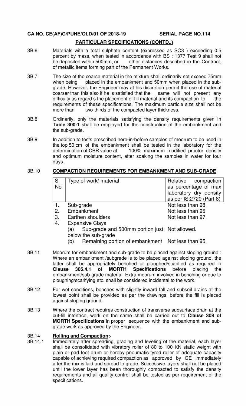
3B.10 COMPACTION REQUIREMENTS FOR EMBANKMENT AND SUB-GRADE
Sl No
Type of work/ material Relative compaction as percentage of max laboratory dry density as per IS:2720 (Part 8)
1. Sub-grade Not less than 98. 2. Embankment Not less than 95 3. Earthen shoulders Not less than 97. 4. Expansive Clays
(a) Sub-grade and 500mm portion just below the sub-grade (b) Remaining portion of embankment
Not allowed.
Not less than 95.
3B.11 Moorum for embankment and sub-grade to be placed against sloping ground :
Where an embankment /subgrade is to be placed against sloping ground, the latter shall be appropriately benched or ploughed/scarified as required in Clause 305.4.1 of MORTH Specifications before placing the embankment/sub-grade material. Extra moorum involved in benching or due to ploughing/scarifying etc. shall be considered incidental to the work.
3B.12 For wet conditions, benches with slightly inward fall and subsoil drains at the lowest point shall be provided as per the drawings, before the fill is placed against sloping ground.
3B.13 Where the contract requires construction of transverse subsurface drain at the cut-fill interface, work on the same shall be carried out to Clause 309 of MORTH Specifications in proper sequence with the embankment and sub-grade work as approved by the Engineer.
3B.14 Rolling and Compaction:-
3B.14.1 Immediately after spreading, grading and leveling of the material, each layer shall be consolidated with vibratory roller of 80 to 100 KN static weight with plain or pad foot drum or hereby pneumatic tyred roller of adequate capacity capable of achieving required compaction as approved by GE immediately after the mix is laid and spread to grade. Successive layers shall not be placed until the lower layer has been thoroughly compacted to satisfy the density requirements and all quality control shall be tested as per requirement of the specifications.
CA NO. CE(AF)G/PUNE/OLD/01 OF 2018-19 SERIAL PAGE NO.115
PARTICULAR SPECIFICATIONS (CONTD..)
3B.14. 2 Rolling shall commence at edges and progress towards the center, except at super elevated portions where it shall commence at the inner edge and progress outer edge. During rolling the surface shall be frequently checked for grade and cross fall (camber) and any irregularities corrected by loosening the material and removing/adding fresh material. Compaction shall continue until the density/achieved is at least 98% of the maximum dry density for the material determined in accordance with IS 2720 (Part VIII).
3B.14. 3 During rolling it shall be ensured that roller does not bear directly on hardened or partially hardened treated material previously laid other than water may be necessary for achieving the specified compaction at the joint.The final surface shall be well closed, free from movement under compaction planes, ridges, cracks or loose material. All loose or segregated or other wise defective areas shall be made good to the full thickness of the layer and re-compacted.
3B.14. 4 The field density of compacted layer shall be measured by “Sand Replacement Method” as specified in IS : 2720 (Part XXVIII).
3B.14. 5 Surface Finish:
(i) The finished surface shall be true to level and conform to the lines, grades, camber and dimension as directed. The finished surface shall be true to level, grade and camber, when a straight edge of 3 metres length is placed longitudinally or transversally. The maximum undulations shall not be more than 15mm longitudinally and 12mm in the transverse direction. The maximum number of undulations exceeding 18mm in any 300 metres length shall not exceed 30. Undulations of size bigger than that specified above shall be made good after loosening the area and adding/removing materials and re-compacting to the required density under OMC conditions.
(ii) Horizontal alignment: Horizontal alignments shall be reckoned with respect to the centerline of the Runway, taxi-track and aprons as shown on the drawings. The edges as constructed shall be correct within a tolerance of +10mm there from.
(iii) Longitudinal profile: The level of the sub grade and different pavement courses as constructed, shall not vary from those calculated with reference to the longitudinal and cross profile drawn or as directed by the GE within the tolerance mentioned below: -
(a) Sub-grade +20mm-25mm (b) Sub-base +10mm (iv) Surface Regularity of Sub-grade and Pavement Course: The
surface regularity of completed sub grade and sub base in the longitudinal and transverse directions shall within the tolerance indicated below in the table. The longitudinal profile shall be checked with a 3 metre long straight edge, at the middle of each 3 metre longitudinal strip along a line parallel to the centerline of that particular type of construction. The transverse profile shall be checked with a set of camber boards at intervals of 10 metres.
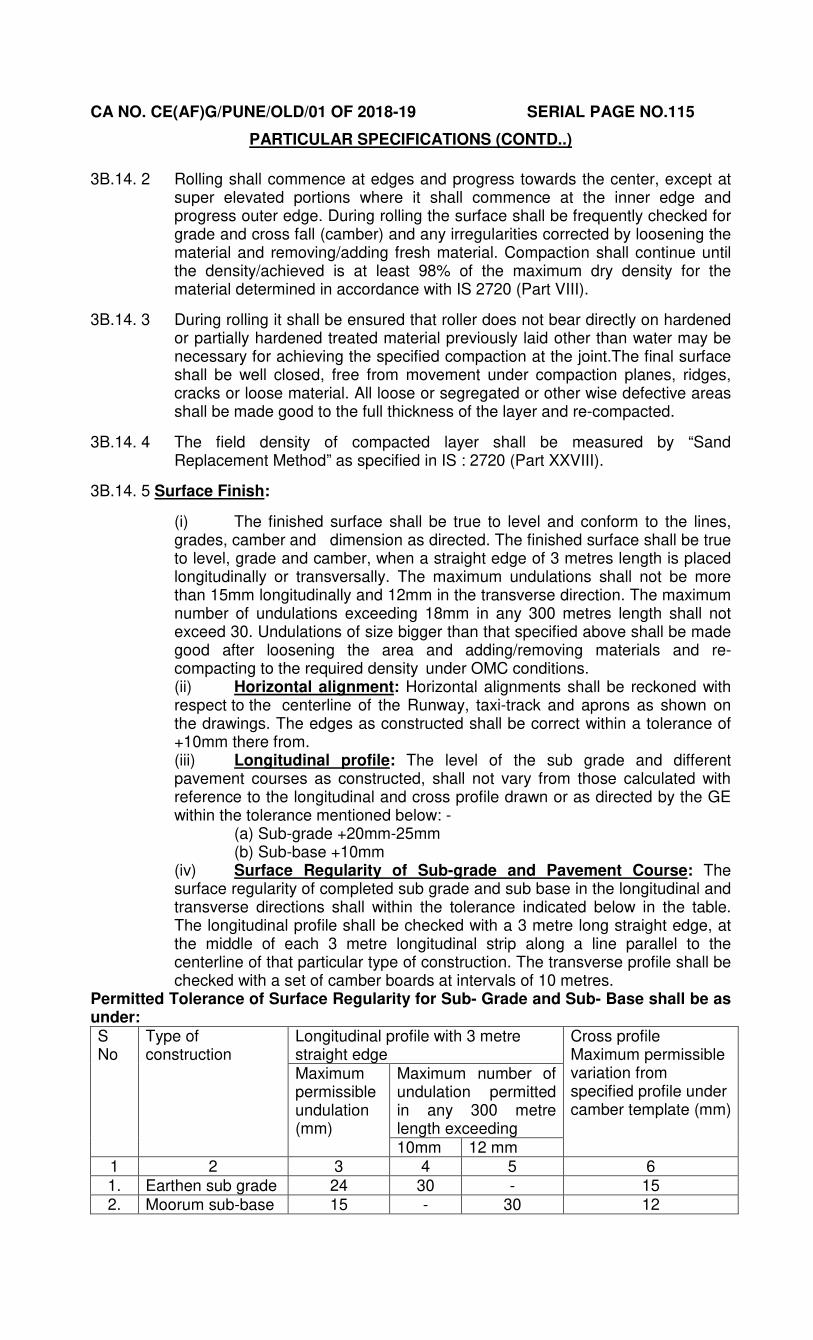
Permitted Tolerance of Surface Regularity for Sub- Grade and Sub- Base shall be as under: S No
Type of construction
Longitudinal profile with 3 metre straight edge
Cross profile Maximum permissible variation from specified profile under camber template (mm)
Maximum permissible undulation (mm)
Maximum number of undulation permitted in any 300 metre length exceeding 10mm 12 mm
CA NO. CE(AF)G/PUNE/OLD/01 OF 2018-19 SERIAL PAGE NO.116
PARTICULAR SPECIFICATIONS (CONTD..)
3B.15 TEST ON EARTH WORK FOR EMBANKMENT
(a) MATERIAL
Sl No Test Test method Frequency (minimum)
1. Sieve analysis (Gradation) IS:2720 (Part IV) 1 test per 250 cum soil. 2. Sand Content IS: 2720 (Part IV) 2 test per 3000 cum of soil 3. Plasticity test IS: 2720 (Part V) 2 test per 3000 cum of soil. 4. Density test IS: 2720 (Part VIII) 2 test per 3000 cum of soil. 5. Deleterious Content Test IS: 2720 (Part XXVII) As and when required by
GE 6. Moisture content test IS: 2720 (Part II) 1 test for every 250 cum of
soil. 7. CBR test on materials to
be incorporated in the subgrade or soaked/ unsoaked samples.
IS: 2720 (Part XVI) 1 test for every 3000 cum of soil and one test of every 100m length of existing runway portion after excavation, watering, rolling of sub grade
8. Plate load test for determination of K value
IS:2720 Minimum 04 No test shall be done on main runway, 02 each on ORP /Dispersal areas
(b) COMPACTION CONTROL: -
(i) Control shall be exercised by taking at least one measurement of density for each 1000 square metre of compacted area, or closer as required to yield the minimum number of test results for evaluating a day’s work on statistical basis. The determination of density of shall be in accordance with [IS: 2720 (Part XXVIII)]. Test locations shall be chosen only through random sampling techniques. Control shall not be based on the result of any one test but on the mean value of a set of 5-10 density determinations. The number of tests in one set of measurements shall be five as long as it is felt that sufficient control over borrow material and the method of compaction is being exercised. If considerable variations are observed between individual density results, the minimum number of tests in one set of measurement shall be increased to The acceptance of work shall be subject to as per table 300-2 of MORTH.
3B.15.1 Rate: The quoted rates of relevant items of schedule shall deemed inclusive of the cost of all materials, plant, machinery and labour required for all the operations described above including all cartages, leads and lifts.
3B.16 Measurement:
3B.16.1 The initial levels shall be taken at fixed interval of 3 metre or less as directed by the GE longitudinally as well as transversally. These levels shall be recorded in field books and plotted on plan before start of work both duly signed by the Engineer-in-Charge and the contractor in token of acceptance. If the work of levelling is carried out using total station in such use computer print out duly bonded will serve as field book/level book. After completion of work i.e. compaction of soil/moorum upto required level gradient and camber, the final levels shall be taken at grid points, where previously the ground levels were taken in the presence of contractor or his authorized representative and his dated signatures obtained on the level book in token of his acceptance. These levels shall make the basis of payment. The quantity shall be computed in cubic metres from cross-sections after compaction. The quantity for payment shall be the theoretical quantity (based on formation levels) or actual quantity (based on actual levels) whichever is less.
CA NO. CE(AF)G/PUNE/OLD/01 OF 2018-19 SERIAL PAGE NO.117
PARTICULAR SPECIFICATIONS (CONTD..)
3B.16.2 The initial levels duly plotted as “longitudinal section” & “cross section” duly signed by Engineer-in-Charge, GE & Contractor shall be forwarded to Accepting Officer within a week of finalization of the levels.
3B.16.3 Computation of quantities can be made using suitable software, random check of quantity calculated by software shall be made by GE to satisfy himself correctness of quantity worked out by soft ware.
3.6 SAND FILLING 3.6.1 Sand filling (Layer) below polyethylene film shall be of single size 1.18mm and
3.7 Hard Core 3.7.1 The material for hardcore (broken stone) shall be as per sample kept in GE’s
office and from the sources as described in Appendix ‘C’ to particular specifications.
3.7.2 Hardcore shall be stones of gauge not exceeding 63mm grade. Hardcore shall be deposited, spread and leveled in layers n exc 15cm thick and watered, well rammed to a true surface and compacted. The thickness of the hardcore after consolidation shall be as per drawings and where not specifically shown on drawings, it shall be 150 mm consolidated thickness.
4. CEMENT 4.1 Cement required for the work under the contract shall be procured, supplied
and incorporated in the work by the contractor under his own arrangement. Cement shall be of tested quality and shall comply with the requirements mentioned in the SSR, IS specifications and particular specifications given hereinafter
4.1.1 TYPE OF CEMENT:- Cement shall be Ordinary Portland Cement (OPC) Grade 43 conforming to IS 8112-1989 (Latest revision) use of OPC 53 grade cement for runway work shall not be permitted.
4.1.2 The checks and procedures for procurement and testing as specified hereinafter shall be followed before the cement supplied by the contractor is accepted and is approved for incorporation in the works.
4.1.3 PROCUREMENT: Cement shall be procured from the manufacturers /main producers as mentioned in Appendix `B’.
4.1.3.1 The contractor shall furnish the particulars of the manufacturers of cement along with the date of manufacture to the GE for every lot of cement separately. The documents in support of the purchases of cement shall be verified by the site staff and GE. The cement so brought shall be fresh and in no case older than 30 days from the date of manufacture. Before placing the order for cement by the contractor, he shall obtain written approval from the GE regarding name of manufacturer, quantity of cement etc. Cement shall be procured for requirement of not more than two months at a time. The cement shall be consumed in the work within three months from date of procurement.
CA NO. CE(AF)G/PUNE/OLD/01 OF 2018-19 SERIAL PAGE NO.118
PARTICULAR SPECIFICATIONS (CONTD..)
4.1.3.1 (Contd)….
If the cement is not consumed within 90 days such cement shall be removed from site without any extra cost to the department. Cement shall conform to the requirements of IS specification and each bag of cement shall bear relevant ISI mark. The weight of each consignment shall be verified by the GE and recorded. The content of cement shall be checked at random to verify the actual weight of cement per bag.
4.1.4 ------- BLANK --------
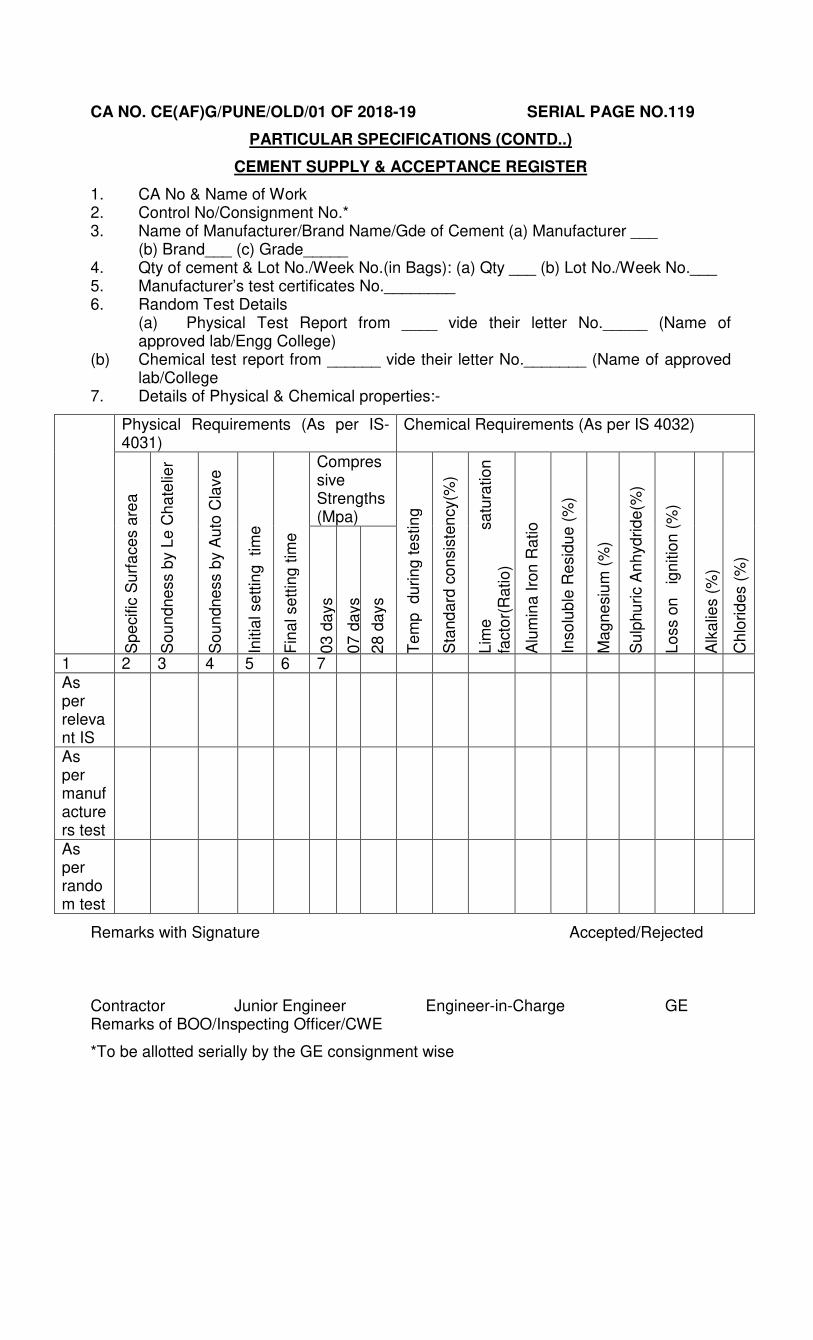
4.1.5 TESTING OF CEMENT: (a) The manufacturer/main producer shall carry out inspections and
testing of cement in accordance with the relevant BIS provisions. The contractor shall submit the manufacturer’s Test Certificate in original along with the Test sheet giving the result of each physical test as applicable in accordance with relevant IS provisions and the chemical composition of the cement or authenticated copy thereof, duly signed by the manufacturer with each consignment.
(b) The Engineer-in-Charge shall record these details in the Cement supply and Acceptance Register given here in below, after due verification: -
CA NO. CE(AF)G/PUNE/OLD/01 OF 2018-19 SERIAL PAGE NO.119
PARTICULAR SPECIFICATIONS (CONTD..)
CEMENT SUPPLY & ACCEPTANCE REGISTER
1. CA No & Name of Work 2. Control No/Consignment No.* 3. Name of Manufacturer/Brand Name/Gde of Cement (a) Manufacturer ___ (b) Brand___ (c) Grade_____ 4. Qty of cement & Lot No./Week No.(in Bags): (a) Qty ___ (b) Lot No./Week No.___ 5. Manufacturer’s test certificates No.________ 6. Random Test Details (a) Physical Test Report from ____ vide their letter No._____ (Name of approved lab/Engg College) (b) Chemical test report from ______ vide their letter No._______ (Name of approved lab/College 7. Details of Physical & Chemical properties:-
Physical Requirements (As per IS-4031)
Chemical Requirements (As per IS 4032)
Sp
ecific
Su
rfa
ce
s a
rea
So
und
ne
ss b
y L
e C
ha
telie
r
So
und
ne
ss b
y A
uto
Cla
ve
Initia
l se
ttin
g tim
e
Fin
al se
ttin
g t
ime
Compressive Strengths (Mpa)
Te
mp
du
rin
g te
stin
g
Sta
nd
ard
co
nsis
ten
cy(%
) L
ime
sa
tura
tio
n
facto
r(R
atio
) A
lum
ina
Iro
n R
atio
Inso
lub
le R
esid
ue
(%
) M
ag
ne
siu
m (
%)
Su
lphu
ric A
nh
yd
rid
e(%
) L
oss o
n
ig
nitio
n (
%)
Alk
alie
s (
%)
Ch
lorid
es (
%)
03
da
ys
07
da
ys
28
da
ys
1 2 3 4 5 6 7 As per relevant IS
As per manufacturers test
As per random test
Remarks with Signature Accepted/Rejected Contractor Junior Engineer Engineer-in-Charge GE Remarks of BOO/Inspecting Officer/CWE
*To be allotted serially by the GE consignment wise
CA NO. CE(AF)G/PUNE/OLD/01 OF 2018-19 SERIAL PAGE NO.120
PARTICULAR SPECIFICATIONS (CONTD..)
4.1.5 (Contd…) (c) The GE shall also organize independent physical testing of random
samples of cement drawn from each lot from the NATIONAL TEST HOUSE, SEMT WING CME, REGIONAL RESEARCH LABORATORIES, GOVERNMENT APPROVED LABORATORIES, ZONAL LABORATORIES as per IS 3535-1986 (Method of sampling hydraulic cement) IS-4031 (Method of physical test for hydraulic cements) and IS-4032 1985 (Method of chemical analysis of hydraulic cement) and record the results in the relevant portion of Cement supply and Acceptance Register. In order to undertake departmental testing, requisite facilities along with materials, conveyance etc shall be organized by the contractor without any extra cost to the Govt. The random samples of cement to be tested shall be drawn as per Quality Assurance Manual. The contractor shall be required to set up adequate testing facilities at site to the entire satisfaction of Garrison Engineer for conducting setting time test and compressive strength test as per IS codes referred to hereinbefore for the samples collected from the lot brought at site. These tests shall be carried out within 7 days of receipt of cement at site. The tests can alternatively be carried out any recognized Government laboratory so designated by GE. The contractor shall be allowed to use the cement only after satisfactory compressive strength of 7 days. 7 days strength will be relied up-on to accept the lot of cement. 28 days compressive strength test will be the final criteria to accept/reject the lot.
(d) The cost of materials for testing, samples, conveyance etc shall be borne by the contractor irrespective of the test result. However the cost of testing charges shall be governed in terms of condition 10(A) of IAFW-2249. In case as per the result of independent test, the cement is found to be not of requisite standard despite manufacturer’s test certificate, the contractor shall remove the total consignment from the site within 24 hours at his own cost after written rejection order of consignment by the GE.
(e) The record of random samples selected by the GE for testing shall be properly maintained in the cement testing register giving cross reference to relevant consignment of cement and quantity received etc.
4.1.6 Storage/Accounting /Preservation of Cement 4.1.6.1 Cement shall be stored in covered godown over dry platform at least 20cm
high in such a manner so as to prevent deterioration due to moisture or intrusion of foreign matter. In case of storeroom, the stack should be at least 20cm away from floors and walls. The stacking of cement shall be done as specified in relevant IS. The storage, accounting and preservation of cement supplied by the contractor shall be done as per standard engineering practice till the same is incorporated in the work and the cost of the same shall be deemed to be included in the unit rate/ amount quoted by the tenderer. The EIC shall inspect once a day to verify that cement lying at site is stored, accounted, preserved and maintained as per the norms. The cement shall be stored so as to differentiate each tested and untested consignment separately with distinct identification. If the GE is not satisfied with the storage/preservation of cement, he may order for any test(s) of cement as applicable for that consignment to ensure its conformity to the quality mentioned in the manufacturer’s test certificate. The contractor shall bear the cost of necessary testing(s) in this regard and no claim whatsoever shall be entertained.
4.1.6.2 Stacking of cement shall be done as per relevant IS and as under: -
(a) Each cement consignment shall be stacked separately and removal shall be made on the basis of ‘First in First out’.
(b) Adequate top cover will be provided.
CA NO. CE(AF)G/PUNE/OLD/01 OF 2018-19 SERIAL PAGE NO.121
PARTICULAR SPECIFICATIONS (CONTD..)
4.1.6.2 (Contd….)
(c) Stacks in no case shall be higher than 10 bags. The maximum width of each stack shall be 3. 00m. If the stack is to be more than 7 or 8 bags high, the bags shall be arranged in header and stretcher fashion, i. e. alternatively lengthwise and crosswise so as to tie the piles together and avoid danger of toppling over.
(d) Adequate space shall be kept between two stacks.
4.1.6.3 Cement godown shall be provided with two locks on each door. The key of one lock of each door shall remain with the EIC or his representative and that of the other lock with the contractor’s authorized agent at site of work so that cement is removed from the godown only according to daily requirement with the knowledge of both the parties. During the period of storage, if any cement bag(s) is found to be in damaged condition due to what so ever reason, the same shall be removed from the cement godown on written orders of the GE and suitable replacement for the cement bags so removed shall be made and no claim what so ever shall be admissible on this account.
4.1.6.4 Cement shall be removed from the store only according to daily requirement with the knowledge of both the parties and daily consumption of cement shall be recorded in cement consumption register which shall be signed by Engineer-in-Charge and the contractor. Cement constants given in Appendix ‘A’ to E-in-C’s Branch letter No. 19280/E8 dated 03 May 1976 shall form the basis of consumption of cement for various items of works unless specifically indicated otherwise.
4.1.6.5 The register shall be kept at site in the safe custody of the contractor during progress of the work and he shall, on demand be produced, the same for verification of Inspecting Officer. On completion of the work, register shall be handed over to the Engineer-in-Charge for record with the MES.
4.1.6.6 In case the consumption of cement as per cement consumption register is found to be more than the estimated quantity of cement due to what so ever reason, the contractor shall not have any claim what so ever for such excess consumption of cement.
4.2 Schedule of supply: - The contractor shall procure the cement timely as required in accordance with
CPM/PERT chart agreed between GE and the contractor. The contractor will forfeit his right to demand extension of time if the supply of cement got delayed due to his failure in placing order in time to the manufacturer.
4.3 Measurement and Payment of Cement: - 4.3.1 The entire quantity of cement shall also be suitably recorded in the
Measurement Book for record purposes as ‘Not to be abstracted’ before incorporation in the work and shall be signed by the engineer-in-charge and the contractor.
4.3.2 The payment shall only be allowed after production of original purchase vouchers, certified copies of test certificates from manufacturer for each consignment and result of testing carried out in laboratory on receipt of cement (7 days compressive test) are found satisfactory after testing as specified here in before. Cement shall be paid as material lying at site as per Condition 64 of IAFW-2249.
4.4 PLAIN CEMENT CONCRETE WORK: 4.4.1 All Plain cement concrete shall comply the requirement of IS-456-2000.
4.4.2 CEMENT: Refer clause 4.1.1 given here-in-before.
CA NO. CE(AF)G/PUNE/OLD/01 OF 2018-19 SERIAL PAGE NO.122
PARTICULAR SPECIFICATIONS (CONTD..)
4.4.3 COARSE AND FINE AGGREGATE: 4.4.3.1 Aggregate shall conform to IS 383 and shall be from the source (s) mentioned
in Appx ‘C’ to the particular specifications. Aggregate shall be non-porous, hard, strong, durable clean and free from various impurities and adherent coating and shall not contain any deleterious materials exceeding the limits specified in the above referred IS. The contractor shall at his own expense carry out all tests detailed in Appendix ‘D’ to verify that the aggregate comply with the requirement of IS. The tests shall be carried out in any laboratory as approved by GE.
4.4.3.2 Coarse aggregate shall consist of crushed stone aggregate. The size and grading of the aggregate shall be as specified in clause 4.4.7 of MES SSR Part I.
4.4.3.3 Fine aggregate shall consist of naturally occurring coarse sand. Fine aggregate shall conform to zone II or zone III of table IV of IS-383 and shall be from the source(s) mentioned in Appendix ‘C’ to particular specifications.
4.4.3.4 Samples of the aggregate proposed to be used shall be approved by the GE, prior to bulk delivery of the same at site of work. Field tests for determining the contents of loam, clay etc, for fine aggregate shall be carried out by the Engineer-in-Charge from time to time to ensure that the materials brought to site are in conformity with the samples approved by the GE.
4.4.3.5 Grading of Aggregate: The grading of coarse and fine aggregate shall be as per MES Schedule. Grading of coarse and fine aggregate shall be checked as frequently as possible. The frequency for a given job shall be determined by Engineer-in-Charge to ensure that the specified grading is maintained.
4.4.4 Vibratory Type Sand Screener: 4.4.4.1 The sand to be used in the work shall be screened by using vibratory sand
screener of appropriate capacity. The screener will have eccentric vibrator having capacity 1500 vibrations per minute. The screener will have two MS wheels for easy mobility.
4.5 Grading of coarse aggregate. Graded Aggregate of nominal sizes shall be as given in Schedule ‘A’. The type and mix of cement concrete shall be as described in Sch ‘A’.
4.6 Water: Water shall conform to the requirement stipulated in clause 5.3 of IS 456-2000 and as per clause 4.9 of MES SSR Part-I.
4.7 Important Requirements of plain cement concrete. 4.7.1 All materials, workmanship, inspection and testing for cement concrete shall
be as per the requirement given in IS-456, IS-10262 and SP-23.
4.7.2 Plain cement concrete shall be mixed in mechanical mixer of approved type in accordance with IS 456:2000 (Clause 10.3).
4.7.3 Plain cement concrete shall be transported, laid, rammed and consolidated by tamping and rolling as specified in MES SSR Part-I.
To be taken as per mix designed as per IS-10262 clause 2.2
(iv) Aggregate/cement ratio by weight
As per mix design based on IS 10262 and IS-456-2000
(v) Workability As per clause 7.1 of IS-456-2000 slump shall be 25mm to 75mm.
CA NO. CE(AF)G/PUNE/OLD/01 OF 2018-19 SERIAL PAGE NO.123
PARTICULAR SPECIFICATIONS (CONTD..)
4.8.1 (Contd….)
(vi) Max free water cement ratio As per mix design based on IS-10262 and IS-456-2000
(vii) Degree of quality control Good (Refer Appendix ‘A’ of IS-10262)
(viii) Durability Exposure – Severe (ix) Cement Content
As per IS-456-2000
(x) Type of aggregate
Crushed stone aggregate
(xi) Max nominal size of Aggregate
20mm or as specified in schedule ‘A’.
(xii) Grade of concrete
M-30 (Design Mix)
NOTE (a) Mix design shall be prepared based on SP-23, handbook on concrete
mixes and IS-10262. Recommended guidelines for concrete mix design. No element of wastage of cement shall be allowed while working out the cement consumption details for design mix concrete work.
(b) No price adjustment for design mix shall be applicable irrespective of the quantity of cement approved/used in the execution of design mix concrete work. The contractor is required to keep this aspect in mind while quoting his rates.
4.9.1 Approval of Design Mix (a) Soon after commencement of work, contractor shall arrange the design mix for M-30 grade concrete. Design mix concrete shall be got carried out from National Test House, SEMT, CME, and Regional Research Laboratories or from any Govt approved labs such as Govt Engineering Colleges and shall be got approved from GE before implementation in the work. In case contractor fails to submit the samples of design mix soon after commencement of work, the delay shall solely be attributable to the contractor and no claim of whatsoever nature shall be admissible on this account.
(b) As soon as possible after receiving the design mix from the above agency same shall be verified at site by casting & testing the final cubes by GE.
(c) For each design mix six numbers of preliminary test cubes of size 15x15x15 cm shall be made as per clause 2.8, 2.9 and 2.10 of IS-516. The concrete cube shall be tested as per IS-516 at site laboratory. Out of six cubes three will be tested after seven days (on 8th day) from the date of casting, three cubes after 28 days from the date of casting.
(d) The test after seven days (ie on 8th days) is intended only to give an early indication of the strength likely to be achieved. The strength thus achieved should be comparable with the above design mix report with specified design parameters as specified in hereinbefore.
(e) Frequency of sampling shall be as per clause 15 of IS-456. On the result of the above test the mix actually to be used shall be agreed to and approved by the GE. The approval of the GE shall not relieve the contractor of his responsibility for obtaining the required minimum strength of quality concrete in the works test cubes.
4.9.2 Acceptance Criteria.
(a) The contractor shall be deemed to comply with the strength
requirement as per clause 16 of IS-456.
CA NO. CE(AF)G/PUNE/OLD/01 OF 2018-19 SERIAL PAGE NO.124
PARTICULAR SPECIFICATIONS (CONTD..)
(b) Whenever there is any change in the type of grading of material, the mix should be rechecked and modified suitably to the desired compressive strength.
(c) Actual standard deviation for each grade of concrete is to be calculated after collecting the test results of actual concrete work (compressive strength actually achieved at site for 1st 30 samples) as laid down in IS-456 (Table-II) to review the Design Mix.
4.10 HOT WEATHER CONCRETING Para 14.1 of IS-459 specifies that during hot and cold weather, the concreting should be done as per the procedure set out in IS 7861 (Part-I) & IS 7861 (Part-II). Provision contained in IS 7861, reaffirmed 1990 shall be taken in to account and nothing extra on this account shall be paid by the Dept. The procedure/combination of procedures to be followed for bringing down the temperature of concrete shall be decided by the GE as per site requirement.
4. 11 TESTING CHARGES: Sampling and testing shall be carried out as per requirement given in Appendix ‘D’.
4. 12 MIXING AND COMPACTION OF CEMENT CONCRETE
4.12.1 All cement concrete shall be mixed in an approved mechanical mixer. The mixer must also have a water container with a water meter for adding measured quantity of water in each batch. Mixing of concrete shall be all as per clause 4.11.5 of MES SSR Part I.
4.12.2 All concrete shall be consolidated with approved mechanical vibrators except where not practicable in the opinion of the Engineer-in-Charge. RCC in slab shall be compacted with plate/surface vibrators & in beam/columns, needle/pin vibrators.
5.0 PRECAST PCC SOLID BLOCK MASONARY 5.1 PCC solid blocks shall conform to IS-2185.
5.2 Type of mix:- The precast PCC solid block shall be of PCC (1:5:8) ie. One part cement, five parts sand and eight part aggregates (05 part 20mm and 03 part 12.5mm stone aggregates). Aggregates shall be mixed thoroughly to achieve desired grading. PCC blocks with above mix shall be checked and verified for 28 days compressive strength as per IS 2185 at the commencement of work and whenever there is change in source of ingredients. The block shall have minimum compressive strength of 50 Kg/cm2.
5.3 The mix ratio as given is minimum and is only for guidance. Trial mixes shall be carried out before casting the blocks to ensure that the required strength and block density is achieved as per IS. In case superior mix ratio is required to achieve the desired strength, nothing extra will be paid to contractor on this account.
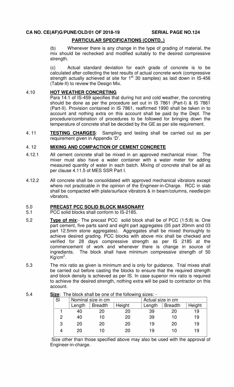
5.4 Size: The block shall be one of the following sizes: - Sl Nominal size in cm Actual size in cm
Length Breadth Height Length Breadth Height
1 40 20 20 39 20 19
2 40 10 20 39 10 19
3 20 20 20 19 20 19
4 20 10 20 19 10 19
Size other than those specified above may also be used with the approval of Engineer-in-charge.
CA NO. CE(AF)G/PUNE/OLD/01 OF 2018-19 SERIAL PAGE NO.125
PARTICULAR SPECIFICATIONS (CONTD..)
5.5 MATERIAL (AGGREGATE) 5.5.1 Coarse aggregate – These shall be crushed or natural aggregates 20 mm
and down size of approved quality and shall conform to IS-383.
5.5.2 Fine aggregates (sand)- This shall be free form dust and well graded.
5.5.3 A block shall be deemed to be solid if the solid material is not less than 75% of the total volume of the block calculated from the overall dimension.
5.6 MANUFACTURE OF BLOCKS 5. 6.1 The block shall be machine made. The mixing of concretes, manufacture of
block, curing and drying shall be in accordance with the Para 6 to 10 of IS-2185.
5.6.2 Faces of the block shall be flat and rectangular.
5. 6.3 Mixing – Concrete shall be mixed in mechanical mixer. Mixing shall be continued until there is uniform distribution of material and the mix is uniform in colour and consistent.
5.7 Placing and compaction (i) In case of mechanical compaction, the mould shall be filled up to over
flow, vibrated or mechanically tamped and struck off level.
(ii) After remoulding the block shall be protected until they are sufficiently hardened to permit handling without damage.
5.8 Curing- The block hardened as mentioned here in before shall then be cured in the curing water tank or in curing yard and shall be kept continuously moist for at least 14 days. Where the blocks are cured in an immersion tank, the water of tank shall be changed at least every 4 days.
Note: - Curing yard is a paved yard sub divided by shallow drains 4 to 5 metre, Square platform which are provided with water fountain in the centre. The blocks are stacked on the platform around the fountain, which works continuously. The fountain is connected to an elevated water storage tank.
5. 9 Drying: - After curing the block shall be dried for a period of 4 week before being used in the work. They shall be stacked with voids horizontal to facilitate thorough passage of air. The dimensioned stability of concrete block is greatly affected by variation in their moisture content. Since the shrinkage of the block is much greater at the time it dries for the first time than due to subsequently wetting and re drying, it is necessary to ensure that the blocks are dried so that initial shrinkage is completed before they are delivered to use. Further their moisture content should not exceed 25% of their maximum water absorption capacity, if the blocks are to be used in situation where the relative humidity of air average more than 60% the blocks can be dried to a moisture content of 40 % of their maximum water absorption capacity.
5.10 PHYSICAL REQUIREMENT 5 10.1 General:- All blocks shall be sound and free form cracks or other defects
which interfere with proper placing of the block or impair the strength or performance of the construction. Minor chipping resulting from the customary methods handling during delivery shall not be deemed the ground for rejection.
5.10.2 Tolerance: - The maximum variation in the length of the units shall not be more than + 5mm for length and maximum variation in heights and width of unit, not more than + 3mm.
5.11 Block Density: - The block density shall be as per para 4 of IS 2185 for solid PCC blocks. It shall not be less than 1800 kg/M3.
5.12 Compressive strength: - The average compressive strength of eight blocks when determined in the manner described in IS-2185 shall not be less than 50 kg/sq cm of gross area. The strength of lowest individual block shall be not less than 80% of the average compressive strength of eight blocks.
CA NO. CE(AF)G/PUNE/OLD/01 OF 2018-19 SERIAL PAGE NO.126
PARTICULAR SPECIFICATIONS (CONTD..)
5.13 Water Absorption: - The water absorption shall be as per IS-2185.
5.14 Drying shrinkage and moisture movement shall be as per IS 2185.
5.15 TESTS 5.15.1 Tests as described in appendices ‘A’ to ‘F’ of IS-2185 shall be conducted on
samples of blocks selected according to the samples procedure given in Para 1(c) of IS-2185 to ensure conformity with the physical requirement laid down in Para 8 of IS-2185. Cost of testing such as transportation, casting of block, testing fee and other expenses shall be borne by the contractor. The tests listed in Appendix ‘A’ to IS-2185 shall be conducted from the laboratory as approved by GE and other tests shall be carried out as listed in Appendix ‘D’ to Particular Specifications.
5.15.2 SAMPLING CRITERIA FOR CONFORMITY The blocks required for carrying out the test laid down in standard shall be
taken by one of the method given in Para 10 of IS-2185 and shall be considered as conforming to the requirements of the specifications, if the conditions mentioned in Para 11.2 to 11.5 of IS 2185 are satisfied.
5.16 Precast PCC solid block walling: - 5.16.1 PCC block walling shall be built as per item of Schedule ‘A’.
5.16.2 Laying- The block shall be slightly wetted before & during laying in the wall. The block shall be laid with mortar joints completely filled without any void left in the masonry. The thickness of the horizontal and vertical joints shall not exceed 1cm. The 1/2, 1/3 and 2/3 blocks shall be used for breaking the joints. The face joints shall be raked to a depth of 1cm by raking tool during the progress of the work, when the mortar is still green so as to provide proper key for plaster or to facilitate pointing to be done later. Where plaster or pointing is not required the joints shall be struck flush and finished side by side.
5.16.3 Curing of walling- Masonry work shall be kept constantly moist on all the faces for a minimum period of 7 days.
5.16.4 Scaffolding for walling- Only double scaffolding shall be used. The scaffolding shall be strong and sound. No holes in the masonry for supporting scaffolding will be allowed.
6. -----------BLANK--------------
7. STEEL AND IRON WORK 7.1 All type of steel to be used in the work shall be procured by the contractor from
main manufacturers/secondary producers/BIS marked manufacturers as specified in clause 7.2 hereinafter and shall be of quality and grade as specified in drawing and hereinafter (Also refer clause 7.2).
7.1.1 REINFORCEMENT STEEL (a) Reinforcement steel shall be high strength deformed steel bars produced by Corrosion Resistance Steel (CRS) process. CRS Steel bar shall be of grade Fe-500/Fe-500D or Fe-550/Fe-550D as shown on drawing, meeting all other requirement of IS: 1786 and elongation shall be more than 18 percent. Unless otherwise mentioned elsewhere or if not mentioned grade of reinforcement steel shall be Fe-500/Fe-500D or Fe-550/Fe-550D
(b) Fabric reinforcement for concrete shall be ISI marked (IS-1566).
(c) In the event of deviation, for pricing of reinforcement steel using High strength deformed steel bars produced by Corrosion Resistance Steel process (CRS steel bars of grades Fe-500/Fe-500D or Fe-550/Fe-550D), the rate shall be applicable as for TMT bars given in SSR Part II adjusted by applicable percentage for respective parts of schedule ‘A’.
CA NO. CE(AF)G/PUNE/OLD/01 OF 2018-19 SERIAL PAGE NO.127
PARTICULAR SPECIFICATIONS (CONTD..)
7.1.2 Structural Steel
(a) (i) Definition of structural steel as given in clause 10.4 of SSR Part I shall be applicable. Steel for general structural purpose shall be Gde Fe-410WA (grade E-250) quality A ISI marked (IS-2062) for all types of steel structures including those subjected to dynamic loading.
(ii) In the event of deviation, for pricing of steel for general structural purpose Gde Fe-410WA, (grade E-250) quality A the rate shall be applicable as given in SSR Part II adjusted by applicable percentage for respective parts of Schedule ‘A’.
(b) (i) Low tensile structural steel Fe-290 (grade E-165)ISI marked (IS-2062-2006) shall be used for frame of panelled/gauged doors, windows guard bars, hold fasts, steel gate, lugs, grills, hand railing, fencing posts etc.
(ii) In the event of deviation, for pricing of steel for low tensile structural purpose Gde Fe-290, (grade E-165)the rate shall be applicable given in SSR Part II adjusted by applicable percentage for respective part of Schedule ’A’.
7.1.3. GI Sheets. GI sheets (plain and corrugated) shall be ISI marked (IS: 277) and grade of coating shall be as specified in para 7.3 of IS: 277.
7.2 PROCUREMENT
7.2.1 REINFORCEMENT STEEL 7.2.1.1 Reinforcement steel bars of all sizes shall be procured directly from
SAIL/RINL/ TISCO/Other Primary Producers as approved by E-in-C’s Branch.
7.2.1.2 Reinforcement steel of grade Fe-500/Fe-500D or Fe-550/Fe-550D shall not be permitted to be procured from any of the secondary producers.
7.2.2 STRUCTURAL STEEL 7.2.2.1 Structural steel sections shall be procured directly from SAIL/RINL/TISCO/
Other primary producers as approved by E-in-C’s Branch. In case of non-availability of structural steel sections with primary producers, the same can be procured from approved Secondary Producers as given in Appendix ‘B’ with a reduction of 5% (Five percent) of the accepted rates of structural steel. In case the desired section of structural steel is not rolled/ manufactured by primary producer, there shall be no price adjustment in use of structural steel procured from approved secondary producers
7.2.2.2 Before allowing the structural steel from secondary producers GE shall verify that the same is fabricated from billet of ISI marked. Also the valid BIS certification and valid ISO license will be verified by the GE before acceptance and CTC copies thereof will be kept on record.
7.2.3 GALVANISED STEEL SHEETS & FABRIC REINFORCEMENT FOR CONCRETE
7.2.3.1 These shall be procured directly from main producers i.e. SAIL, Rashtriya Ispat Nigam Limited, TISCO/BIS marked manufacturers at the option of contractor without any price adjustment.
7.2.3.2 Galvanised steel sheets & fabric reinforcement for concrete may be procured from authorised dealers of main producers i.e. SAIL, Rashtriya Ispat Nigam Limited, TISCO in case the total requirement is less than 5 tonnes.
7.2.4 LOW TENSILE STRUCTURAL STEEL:- Low Tensile Structural Steel of Gde Fe-290 as in railings, gates, fencing, guard bars, grills, steel chowkats, holdfasts, lugs, nosing bars, fan hooks, dowel bars etc., which do not constitute structural members, can be procured from main producers/ secondary producers/ BIS marked manufacturers or their authorised dealers at the option of contractor without any price adjustment.
7.3 SCHEDULE OF SUPPLY
CA NO. CE(AF)G/PUNE/OLD/01 OF 2018-19 SERIAL PAGE NO.128
PARTICULAR SPECIFICATIONS (CONTD..)
7.3.1 The contractor shall place his demand/requisition of steel by giving adequate lead time as agreed in the CPM chart. The schedule of supply of steel shall be vetted by CWE from time to time.
7.3.2 All finished steel shall be well and clearly rolled to the dimensions, sections and weights specified. The finished material shall be reasonably free from cracks, surface flaws, laminations, rough, jagged and imperfect edges and any other harmful defects and shall be finished in a proper manner. Tolerance on size and weight of reinforcement bars shall not be more than that specified in clause 10.17.4 and 10.17.5 of MES SSR Part I and as specified in relevant IS codes.
7.3.3 For each consignment of steel brought by the contractor before acceptance of the steel, the following actions shall be taken by GE and Engineer-in-Charge
7.3.3.1 Physical verification of steel received to confirm the actual quantity of steel as well as to verify aspects brought out hereinbefore.
7.3.3.2 GE shall obtain original machine numbered paid vouchers of manufacturer from contractor.
7.3.3.3 The GE shall obtain the manufacturer’s test certificate (IN ORIGINAL) along with the test sheet giving results of each mechanical test and the chemical composition of steel (as per IS-1786) or authenticated copy thereof duly signed by manufacturer with each consignment. The test sheet should interlia include results of the tests as enumerated in steel supply/Acceptance form stated hereinafter in clause 7.4.1 (c). The GE/CWE shall also organize independent testing of random samples of steel drawn from various lots from National Test House, SEMT CME, Regional Research Labs, Government and BIS approved labs, with following frequency as enumerated in steel supply/Acceptance form stated here in after in clause 7.4.1 (c): -
STEEL FOR REINFORCEMENT (a) Bars size less than
10 mm 1samples (3 specimen) for each test for every 25 tonne or
part thereof. (b) Bar size 10mm to 16
mm 1 sample (3 specimen) for each test for every 35 tonne or part thereof
(c) Bar size more than 16 mm
1 sample (3 specimen) for each test for every 45 tonne or part thereof
STRUCTURAL STEEL (a) Tensile test
1 test for every 25 tonne of steel or part thereof.
(b) Bend test 1 test for every 10 tonne of steel or part thereof. NOTE (i) For various test, acceptance criteria, tolerances etc refer to relevant
BIS codes and steel supply/acceptance form. (ii) Samples from each lot should be tested for quality and elongation. The
elongation shall not be less than 18%.
7.3.3.4. High strength deformed CRS bars which are brought at site in coils shall be got checked by a board of officers appointed by GE in the presence of contractor to determine the actual weight per unit length by getting a suitable length (not less than three metre) from each coil of respective section which shall be recorded in the MB.
7.3.3.5. Verify the documents listed in 7.3.3.2 & 7.3.3.3 hereinbefore given by the contractor from the manufacturer.
7.3.3.6 No consignment or part thereof shall be allowed to be incorporated in the work until and unless the tests results are obtained and the consignment is passed by GE. Schedule of procurement shall be prepared keeping in view the time lost for testing etc.
7.3.3.7 Three samples of pieces (3.0 metre long) of each section of each consignment shall be retained at the project site till completion of the work. These samples shall be suitably marked and properly preserved.
CA NO. CE(AF)G/PUNE/OLD/01 OF 2018-19 SERIAL PAGE NO.129
PARTICULAR SPECIFICATIONS (CONTD..)
7.3.3.8 Besides above CRS steel received from secondary produces will be tested by GE and CWE in person, before incorporation in the work by simple field test and record shall be maintained. Simple field test involving sand papering the cross section of the CRS bar and dipping the same in chemical solution (Nitral) (consisting of Nitric acid 2% & Alchol 98%) to give a clearly defined annular ring of tempered steel.
7.4 DOCUMENTATION
7.4.1 The following documents shall be maintained in addition to the routine documents maintained as per contract provisions: -
(a) All original vouchers shall be kept in a file serially numbered and to be kept in GEs office.
(b) Test certificate shall be kept in a file serially numbered and to be kept in GEs office.
(c) Steel Acceptance Register, as under shall be maintained by the GE: -
CA NO. CE(AF)G/PUNE/OLD/01 OF 2018-19 SERIAL PAGE NO.130
PARTICULAR SPECIFICATIONS (CONTD..)
STEEL SUPPLY AND ACCEPTANCE REGISTER
1. Contract No & Name of Work : 2. Contract No. : 3. Name of Manufacturer’s TC NO. : 4. Manufacturer : 5. Random Test Details : (a) Physical Test Report from ………………………………….. vide letter No. …………………………… (Name of NABL approved Lab/Govt.Engg College) (b) Chemical Test Report from ………………………………….. vide letter No. …………………………… (Name of NABL approved Lab/Govt.Engg College) 6. Type of steel, dia & quantity
(a) Type : TMT/CRS (b) Dia : mm (c) Actual Weight : MT (d) Conversion : MT CHEMICAL TEST MECHANICAL TEST
(d) In/Out Register for details of receipt, acceptance/rejection and consumption of steel shall be maintained as under: -
Sl. No.
Date Steel In Steel Out Qty Balance
Qty (Tons)
Section Control No.
Qty (Tons)
Section Reasons *
1 2 3 4 5 6 7 8 9 * NOTE: - The following reasons may be mentioned for taking out steel from storage: -
(i) For testing purpose. (ii) For use in work. (iii) Rejected Steel taken out of site.
(e) Register containing results of independent and additional testing by GE. (f) Register containing records of surprise Checks. (g) Inspection registers.
CA NO. CE(AF)G/PUNE/OLD/01 OF 2018-19 SERIAL PAGE NO.131
PARTICULAR SPECIFICATIONS (CONTD..)
7.4.2 In addition to the above documents, the following points shall be kept in view while maintaining the documents: -
7.4.2.1 The original vouchers and the test certificate shall be defaced by the Engineer-in-Charge indicating the contract agreement number and other particulars of work for which used and certified true copies of all such documents shall be maintained by the Engineer-in-Charge with cross reference to the control No. recorded in the steel Acceptance register as referred hereinbefore.
7.4.2.2 All entries in steel Acceptance Register shall be signed by JE (Civil), Engineer-in-Charge and the contractor.
7.4.2.3 The entire quantity of steel shall also be suitably recorded in the measurement Book (MB) for record purpose as not to be abstracted before incorporation in the work and shall be signed by the Engineer-in-Charge and the contractor duly checked by the GE.
7.5 ACCEPTANCE/REJECTION OF STEEL -
7.5.1 The contractor will keep a separate stack of steel brought at site for inspection, away from the accepted stack of steel. In case, the consignment does not meet any of the requirements of the relevant IS codes, the GE shall reject the steel, and it shall be removed from the site within 24 hours at the cost of the contractor.
7.6 PROCEDURE FOR MAKING PAYMENTS FOR STEEL INCLUDING MEASUREMENTS CONVERSION WEIGHT ETC.
7.6.1 The requirement of steel shall be worked out section wise and shall be recorded in separate Register jointly maintained by contractor and Engineer-in-Charge. Day to day record shall also be signed by the contractor as well as Engineer-in-Charge. The register should contain different sheets for each steel sections indicating reference to drawing number, location, number of bars, sketch of each length of bar with dimensions, length of bars with the conversion factors given in MES Schedule Part II. For section not listed in MES Schedule, the IS conversion table shall be followed. The contractor shall not have any claim in case the actual weight of steel items works out to be more than the weight obtained by the standard conversion factor.
7.6.2 On completion of work, the Register will be in the custody of the Engineer-in-Charge and contractor may keep a copy for his record if he so desires.
7.7 PAYMENT OF STEEL BROUGHT BY CONTRACTOR -
7.7.1 Payment of the steel brought by the contractor shall only be released by the GE after taking action on points enumerated above and completing the documents as specified hereinbefore.
7.7.2 Before procurement of steel, contract specification and structural drawings shall be read thoroughly and various grades/types of steel to be incorporated in the work shall be identified and got approved by the contractor from the Garrison Engineer. No over payment shall be made on this account in the RAR. Steel shall be procured sufficiently in advance.
7.7.3 (i) For payment of steel material laying at site brought by the contractor shall be regularized as under: -
Sl No.
Type of steel Rate as applicable in relevant MES Schedule
(a) High strength deformed steel bars produced by Corrosion Resistance Steel (CRS) process (CRS steel bars of grades Fe-500/Fe-500D or Fe-550/Fe-550D meeting all requirements of IS: 1786,
TMT bars
CA NO. CE(AF)G/PUNE/OLD/01 OF 2018-19 SERIAL PAGE NO.132
PARTICULAR SPECIFICATIONS (CONTD..)
7.7.3 (i) (Contd….)
(b) Steel for general structural purpose Gde Fe 410-WA,GradeE-250 (quality-A) ,ISI marked (IS-2062)
Structural steel Gde Fe-410 W Grade E-250 (quality- A).
(ii) The above rates shall be adjusted by applicable percentage for respective parts of schedule ‘A’.
7.8 COST OF ADDITIONAL AND INDEPENDENT TESTS: 7.8.1 REINFORCEMENT STEEL 7.8.1.1 The GE will also organize independent testing of random samples of steel
drawn from various lots from National Test House, SEMT Wing CME, Regional Research Labs, Government approved Labs. Independent tests for steel procured from producers with BIS certification shall be carried out.
7.8.1.2 The contractor at his own cost shall provide all facilities required for the testing and cost of materials consumed in tests shall also be borne by the contractor.
7.8.1.3 For checking nominal mass, tensile strength, bend test, rebend test, test specimen at random shall be selected by the GE at frequency mentioned in Clause No. 10.3.3.3 hereinbefore. For CRS bars bend dia shall be 2D and rebend dia 4D.
7.8.2 STRUCTURAL STEEL, GI SHEET & FABRIC REINFORCEMENT 7.8.2.1 The GE will also organize independent testing of random samples of steel
drawn from various lots from National Test House, SEMT Wing CME, Regional Research Labs, Government approved Labs. Independent tests for steel procured from producers with BIS certification shall be carried out.
7.8.2.2 In both the cases as referred in Clause 10.8.2.2 and 10.8.2.3 above, the contractor at his own cost shall provide all facilities required for the testing and cost of materials consumed in tests shall also be borne by the contractor.
7.8.2.3 For checking nominal mass, tensile strength, bend test, rebend test, test specimen at random shall be selected by the GE at frequency mentioned in Clause No. 10.3.3.3 hereinbefore.
7.9 STORAGE - 7.9.1 Steel of different grades and sizes shall be stacked separately. For each
classification of steel separate areas shall be earmarked. Steel shall be marked with distinct painting marks for easy identification.
7.9.2 Steel will be stored in a manner that, it is always at least 15cm above the GL so as to prevent distortion and corrosion. Any section that has deteriorated and corroded or if considered defective for any other reason the same shall be removed from the site by contractor under his arrangement and cost.
7.9.3 Steel sections which are not likely to be used before onset of monsoon shall be given cement slurry wash so as to ensure steel free from scale and rust. Also steel sections, which are procured during monsoon and are not likely to be used within a week from the date of procurement, shall be given cement slurry wash immediately.
7.10 SAFETY OF STEEL - 7.10.1 It will be responsibility of contractor to make sure that all possible
arrangements are made for safe custody of the steel. In case of any loss of steel, contractor will only be responsible and the loss will be made good without any delay or claim what so ever.
CA NO. CE(AF)G/PUNE/OLD/01 OF 2018-19 SERIAL PAGE NO.133
PARTICULAR SPECIFICATIONS (CONTD..)
7.11 UTILISATION OF SEMT WING, CME PUNE 7.11.1 SEMT Wing, CME Pune is well equipped BIS accredited lab. All test facilities
are available there. Testing facilities of SEMT wing shall be fully utilised wherever possible.
7.12 GENERAL 7.12.1 The details as above incorporated in tender documents is for implementation
by the Department as well as by the Contractor.
7.13 Wherever 6mm and 8 mm MS bars are shown in drawings. It shall be amended to read as 8 mm dia high strength deformed CRS steel bars. Number and spacing of bars shall remain unchanged. Cost of buildings to be quoted against Sch ‘A’ Part-I shall be deemed to include the cost of 8 mm dia high strength deformed CRS steel bars in lieu of 6mm and 8mm dia round bars.
7.14 STEEL FOR REINFORCEMENT 7.14.1 Steel for reinforcement for RCC shall be all as indicated in the drawings. The
provision of MES SSR Part-I clause 10.18 that ends of deformed bars are not bent to form hooks is not applicable to this contract. ‘L’ shaped bends shall be provided to deformed bars all as per RCC notes on drawing No CEAA/TD/109 Sheet No. 1/4 to 4/4.
7.14.2 The overlaps for reinforcement given in drawings No CEAA/TD/109 Sheet No. 1/4 of 4/4 (as applicable) shall take precedence over provisions given in Para 10.19 of MES SSR Part-I.
7.14.3 For making adjustment arising out of deviation involving reinforcement bars, the length of each bar for the purpose of calculation of laps shall be taken as 10 metres.
7.14.4 Adequate numbers of chairs as given in drawing No CEAA/TD/141 Sheet No. 1/1 sheet shall be provided in all reinforced sections to prevent top layer of reinforcement from sagging and the cost of the same shall be deemed to be included in lump sum quoted for schedule ‘A’ Part-I.
7.15 STRUCTURAL STEEL WORKS - 7.15.1 The structural steel works such as roof, rafters purlins, cleat, gusset plates,
base plates shall be provided all as shown on drawing. For all works standard quality Fe 410 WA steel shall be used.
7.15.2 BOLTS, NUTS AND WASHERS - Bolts and nuts shall be of grade ‘BLACK’ (B) conforming to IS-6639 specification for hexagonal bolts for steel structural and all as specified in clause 10.7.2 of MES SSR Part I.
7.15.3 WASHERS - Plain washer shall be of steel conforming to IS-2016 specification for plain washer and all as specified in clause No. 10.7.3 of MES SSR Part I.
7.15.4 ELECTRODES - Electrodes for metal arc welding of mild steel shall be as per IS-814, specification for covered electrodes for metal arc welding of structural steel.
7.15.5 WORKMANSHIP GENERALLY :-Structural steel work welded, riveted or bolted shall be carried out as described in IS-800, code of practice for use of structural steel in general building construction and all as specified in clause 10.9 to 10.16.13.2 of MES SSR Part I and as directed by GE/Engineer-in-Charge.
7.16 WELDING :- Welding wherever shown on drawings shall be by metal arc process in accordance with IS 816 and IS 823 and as per clauses of MES SSR Part I unless specifically indicated otherwise on drawings.
CA NO. CE(AF)G/PUNE/OLD/01 OF 2018-19 SERIAL PAGE NO.134
PARTICULAR SPECIFICATIONS (CONTD..)
8 DRY LEAN CEMENT CONCRETE
8.1 Cement: Refer clause 4 given here-in-before.
8.2 Coarse and Fine Aggregate: 8.2.1 Aggregate shall conform to IS 383 and shall be form the source (s) mentioned
in Appendix ‘C’ to particular specifications. Aggregate shall be non-porous, hard, strong, durable, clean and free from various impurities and adherent coating and shall not contain any deleterious materials exceeding the limits specified in the above referred IS. The contractor shall at his own expense carry out all tests detailed in Appendix ‘D’ to verify that the aggregate comply with the requirement of IS. The tests shall be carried out as per remarks of Appx ‘D’ with approval of GE.
8.2.2 Coarse aggregate shall consist of crushed stone aggregate. No aggregate which has water absorption more than 2 percent shall be used in the concrete mix. The aggregate shall be tested for soundness in accordance with IS : 2386 Part-V. After 5 cycles of testing loss shall not be more than 12%, if sodium sulphite solution is used or 18% if magnesium sulphite solution is used.
8.2.3 Fine aggregate shall consist of naturally occurring coarse sand or crushed stone sand or a combination of the two and shall conform to IS-383. The fine aggregate shall be free from soft particles, clay, shale loam, cemented particles, mica, organic and other foreign matter. Fine aggregates shall not contain deleterious substance more than following: -
Clay Lumps – 1% Coal and Lignite – 1% Material passing IS sieve No 75 Micron – 4%
8.2.4 Samples of the aggregate proposed to be used shall be approved by the GE, prior to bulk delivery of the same at site of work. Field tests for determining the contents of loam, clay etc, for fine aggregate shall be carried out by the Engineer-in-Charge from time to time to ensure that the materials brought to site are in conformity with the samples approved by the GE.
8.2.5 Grading of Aggregate: The grading of coarse and fine aggregate shall be as under: -
Sieve designation % passing the sieve by weight
26.50mm 100
19mm 80-100
9.50mm 55-75
4.75mm 35-60
600 micron 10-35
75 micron 0-5
8.3 Water: Water shall conform to the requirement stipulated in clause 5.3 of IS 456-2000 and as per clause 4.9 of MES SSR Part-I.
8.4 Proportioning of Materials for the Mix
8.4.1 The mix shall be proportioned with a maximum aggregate cement ratio 15:1. The water content shall be adjusted to the optimum 15:1 for facilitating compaction by rolling. The strength and density requirements of concrete shall be determined in accordance with Clause 8.7 hereinafter by making trial mixes.
CA NO. CE(AF)G/PUNE/OLD/01 OF 2018-19 SERIAL PAGE NO.135
PARTICULAR SPECIFICATIONS (CONTD..)
8.4.2 Moisture content: The right amount of water for the lean concrete in main work shall be decided so as to ensure full compaction under rolling and shall be assessed at the time of rolling the trial length. Too much water will cause the lean concrete to be heaving up before the wheels and picked up on the wheels of the roller and too little will lead to inadequate compaction, a low in-situ strength and an open-textured surface. The optimum water content shall be determined and demonstrated by rolling during trial length construction and the optimum moisture content and degree of compaction shall be got approved from the Garrison Engineer. While laying in the main work, the lean concrete shall have a moisture content between the optimum and optimum + 2 percent, keeping in view the effectiveness of compaction achieved and to compensate for evaporation losses.
8.4.3 Cement content. The minimum cement content in the lean concrete shall be between 180 to 200 Kg/Cum of concrete. If this minimum cement content is not sufficient to produce concrete of the specified strength, it shall be increased as necessary without additional cost compensation to the Contractor.
8.4.4 Concrete Strength. The average compressive strength of each consecutive group of 05 cubes made in accordance with IS: 516 shall not be less than 10 Mpa at 7 days. In addition, the minimum compressive strength of any individual cube shall not be less than 7.5 Mpa at 7 days. The design mix complying with the above Clauses shall be got done from any of the IITs/SEMT and shall be got approved from the Garrison Engineer and demonstrated in the trial length construction.
8.5 Sub Grade. The sub grade shall conform to the grades and cross sections shown on the drawings and shall be uniformly compacted to the design strength in accordance with these specifications. The lean concrete sub base shall not be laid on a sub grade softened by rain after its final preparation; surface trenches and soft spots, if any, must be properly back-filled and compacted to avoid any weak or soft spot. As far as possible, the construction traffic shall be avoided on the prepared sub grade. A day before placing of the sub base, the sub grade surface shall be given a fine spray of water and rolled with one or two passes of a smooth wheeled roller after a lapse of 2-3 hours in order to stabilize loose surface. If Engineer feels it necessary, another fine spray of water may be applied just before placing sub base.
8.6 Construction
8.6.1 General: The pace and programme of the lean concrete sub base construction shall be matching suitably with the programme of construction of the cement concrete pavement over it. The sub base shall be overlaid with cement concrete pavement only after 7 days after sub base construction.
8.6.2 Batching and mixing: The automatic computerized concrete plant shall be capable of proportioning the materials by weight, each type of material being weighed separately. Batching plant shall be equipped to proportion aggregates and bulk cement by means of automatic weighing devices using load cells. The cement from the bulk stock shall be weighed separately from the aggregates. The capacity of batching and mixing plant shall be at least 25 per cent higher than the proposed capacity for the laying arrangements. The batching and mixing shall be carried out preferably in a forced action central batching and mixing plant having necessary automatic controls to ensure accurate proportioning and mixing.
8.6.2.1 Weather Conditions at Execution. The concrete should be laid with temperature of concrete between 50 to 300 C. If temperature during the day is not suitable then concrete work should start after 1800 hrs and through the night. Wind speed should not be more than 20 knots during laying as this causes enhanced evaporation of surface water which will lead to shrinkage cracks. Hence, if wind speed increases, then laying should be suspended till it reduces to acceptable limits.
CA NO. CE(AF)G/PUNE/OLD/01 OF 2018-19 SERIAL PAGE NO.136
PARTICULAR SPECIFICATIONS (CONTD..)
8.6.3 Transporting: Plant mix lean concrete shall be discharged immediately from the mixer, transported directly to the point where it is to be laid and protected from the weather by covering the tippers/dumpers with tarpaulin during transit. The concrete shall be transported by tipping trucks, sufficient in number to ensure a continuous supply of material to feed the laying equipment to work at a uniform speed and in an uninterrupted manner.
8.6.4 Placing: (i) Lean concrete shall be laid by paver with electronic sensor. The
equipment shall be capable of laying the material in one layer in an even manner without segregation, so that after compaction the total thickness is as specified. The paving machine shall have high amplitude tamping bars to give good initial compaction to the sub base.
(ii) The laying of the two-lane road sub base may be done either in full width or lane by lane. Preferably the lean concrete shall be placed and compacted across the full width of runway / taxi track by constructing it in one go or into lanes running forward simultaneously. Transverse and longitudinal construction joints shall be staggered by 500-1000mm and 200-400mm respectively from the corresponding joints in the overlaying concrete slabs.
8.6.5 Compaction 8.6.5.1 The compaction shall be carried out immediately after the material is laid and
leveled. In order to ensure thorough compaction, which is essential, rolling shall be continued on the full width till there is no further visible movement under the roller and the surface is closed. The minimum dry density obtained shall be 97 per cent of that achieved during the trial length construction vide Clause 8.8. The densities achieved at the edges i.e. within 0.5m from the edge shall not be less than 95 per cent of that achieved during the trial constructions vide Clause 8.8.
8.6.5.2 The spreading, compacting and finishing of the lean concrete shall be carried out a rapidly as possible and the operation shall be so arranged as to ensure that the time between the mixing of the first batch of concrete in any transverse section of the layer and the final finishing of the same shall not exceed 90 minutes when the concrete temperature is above 25 and below 30 degree Celsius and 120 minutes if less than 25 degree Celsius. This period may be reviewed by the Garrison Engineer in the light of the results of the trial run but in no case shall it exceed 2 hours. Work shall not proceed when the temperature of the concrete exceeds 30 degree Celsius. If necessary, chilled water or addition of ice may be resorted to for bringing down the temperature. It is desirable to stop concreting when the ambient temperature is above 35oC. After compaction has been completed, roller shall not stand on the compacted surface for the duration of the curing period except during commencement of next day’s work near the location where work was terminated the previous day.
8.6.5.3 Double drum smooth-wheeled vibratory rollers of minimum 80 to 100 KN static weight is considered to be suitable for rolling dry lean concrete. In case any other roller is proposed, the same shall be got approved from the Garrison Engineer, after demonstrating its performance. The number of passes required to obtain maximum compaction depends on the thickness of the lean concrete, the compatibility of the mix, and the weight and type of the roller etc. and the same as well as the total requirements of rollers for the job shall be determined during trial run by measuring the in-situ density and the scale of the work to be undertaken.
8.6.5.4 (i) In addition to the number of passes required for compaction there shall be a preliminary pass without vibration to bed the lean concrete down and again a final pass without vibration to remove roller marks and to smoothen the surface.
CA NO. CE(AF)G/PUNE/OLD/01 OF 2018-19 SERIAL PAGE NO.137
PARTICULAR SPECIFICATIONS (CONTD..)
8.6.5.4 (Contd….) (ii) Special care and attention shall be exercised during compaction near joints,
kerbs, channels, side forms and around gullies and manholes. In case adequate compaction is not achieved by the roller at these points, use of plate vibrator shall be made, if so directed by the Garrison Engineer.
8.6.5.5 The final lean concrete surface on completion of compaction and immediately before over laying, shall be well closed, free from movement under roller and free from ridges, low spots, cracks, loose material, pot holes, ruts or other defects. The final surface shall be inspected immediately on completion and all loose, segregated or defective areas shall be corrected by using fresh lean concrete material laid and compacted as per Specification. For repairing honeycombed surface, concrete with aggregates of size 10mm and below shall be spread and compacted. It is necessary to check level of the rolled surface for compliance. Any level/thickness deficiency should be corrected after applying concrete with aggregate, of size 10mm and below after roughening the surface. Similarly the surface regularity also should be checked with 3m straight edge. The deficiency should be made up with concrete with aggregates of size 10mm and below.
8.6.5.6 Segregation of concrete in the dumpers shall be controlled by premixing each fraction of the aggregates before loading in the bin of the batching plant, by moving the dumper back and forth while discharging the mix on it and other means. Even paving operation shall be such that the mix does not aggregate.
8.6.6 Joints: At longitudinal or transverse construction joints, unless vertical forms are used, the edge of compacted material shall be cut back to a vertical face where the correct thickness of the properly compacted material has been obtained.
8.6.7 Curing: As soon as the lean concrete surface is compacted, curing shall commence. One of the following two methods shall be adopted:
(a) The initial curing shall be done by spraying with liquid curing compound. The curing compound shall be white pigmented or transparent type with water retention index of 90 per cent when tested in accordance with BS 7542. Curing compound shall be sprayed immediately after rolling is complete. As soon as the curing compound has lost its tackiness, the surface shall be covered with wet hessian for three days.
(b) Curing shall be done by covering the surface by gunny bags/ hessian, which shall be kept continuously moist for 7 days by sprinkling water.
8.7 Trial Mixes 8.7.1 The contractor shall make trial mixes of dry lean concrete with moisture
contents like 5.0, 5.5, 6.0, 6.5 and 7.0 per cent using cement content specified and the specified aggregate grading but without violating the requirement of aggregate cement ratio specified in Clause 8.4.1. Optimum moisture and density shall be established by preparing cubes with varying moisture contents. Compaction of the mix shall be done in three layers with vibratory hammer fitted with a square or rectangular foot having an area of between 7500 to 14000 Sqmm. The vibrating hammer shall be electric or pneumatic type. The compaction shall be uniformly applied for 60 + 5 seconds with a down ward force of between 300 N and 400 N on each of three layers. After establishing the optimum moisture, a set of six cubes shall be cast at that moisture for the determination of compressive strength on the 3rd and the seventh day. Trial mixes shall be repeated if the strength is not satisfactory by increasing cement content. After the mix design is approved, the Contractor shall construct a trial section in accordance with Clause 8.8.
CA NO. CE(AF)G/PUNE/OLD/01 OF 2018-19 SERIAL PAGE NO.138
PARTICULAR SPECIFICATIONS (CONTD..)
8.7.2 If during the construction of the trial length, the optimum moisture content determined as above is found to be unsatisfactory, the Contractor may make suitable changes in the moisture content to achieve a satisfactory mix. The cube specimens prepared with the changed moisture content should satisfy the strength requirement. Before production of the mix, natural moisture content of the aggregate should be determined on a day-to-day basis so that the moisture content could be adjusted. The mix finally designed should neither stick to the rollers nor become too dry resulting in raveling of surface.
8.8 Trial Bay 8.8.1 The trial bay shall be constructed at least 14 days in advance of the proposed
date of commencement of work. At least 30 days prior to the construction of the trial bay, the Contractor shall submit for the Engineer’s approval a “Method Statement” giving detailed description of the purposed materials, plant, equipment, mix proportion, and procedure for batching, mixing, laying, compaction and other construction procedures. The Garrison Engineer shall also approve the location and length of trial construction, which shall be a minimum of 60m length and for full width of the main runway with thickness as per Sch ‘A’. The trial bay shall contain the construction of at least one transverse construction joint involving hardened concrete and freshly laid sub-base. The construction of trial bay will be repeated till the Contractor proves his ability to satisfactorily construct the sub base.
8.8.2 In order to determine and demonstrate the optimum moisture content which results in the maximum dry density of the mix compacted by the rolling equipment and the minimum cement content that is necessary to achieve the strength stipulated in the drawing, Schedule ‘A’ trial mixes shall be prepared as per Clause 8.7.
8.8.3 After the construction of the trial bay, the in-situ density of the freshly laid material shall be determined by sand replacement method with 20 cm dia density cone. Three density holes shall be made at locations equally spaced along a diagonal that bisects the trial bay; average of these densities shall be determined. These main density holes shall not be made in the strip 50cm from the edges. The average density obtained from the three samples collected shall be the reference density and is considered as 100 per cent. The field density of regular work will be compared with this reference density in accordance with Clause 8.6.5.1. A few cores may be cut as per the instructions of the Engineer to check segregation or any deficiency.
8.8.4 The hardened concrete shall be cut over 3m width and reversed to inspect the bottom surface for any segregation taking place. The trial bay shall be constructed after making necessary changes in the gradation of the mix to eliminate segregation of the mix. The lower surfaces shall not have honeycombing and the aggregates shall not be held loosely at the edges.
8.8.5 The trial bay shall be outside the main works. The main work shall not start until the trial bay has been approved by the Garrison Engineer. After approval has been given, the materials mix proportions, moisture content, mixing laying, compaction plant and construction procedures shall not be changed without the approval of the Garrison Engineer.
8.9 Tolerances for Surface Regularity, Level, Thickness, Density and Strength:- The tolerances for surface regularity, level, thickness, density and strength shall conform to the requirements given in relevant ISI/MOSRT & H clause. Control of quality of materials and works shall be exercised by the Garrison Engineer in accordance with Appendix ‘G’ hereinafter.
8.10 Traffic No heavy commercial vehicles like trucks and buses shall be permitted on the
lean concrete sub base after its construction. Light vehicles if unavoidable may, however, be allowed after 7 days of its construction with prior approval of the Engineer-in-Charge.
CA NO. CE(AF)G/PUNE/OLD/01 OF 2018-19 SERIAL PAGE NO.139
PARTICULAR SPECIFICATIONS (CONTD..)
8.11 Measurements for Payment The unit of measurement for dry lean concrete pavement shall be the cubic
metre of concrete placed, based on the net plan areas for the specified thickness shown on the drawings or as directed by the Engineer.
8.12 Rate The Contract unit rate payable for dry lean concrete sub base shall be
payment in full for carrying out the required operations including all labour, material s and equipment, mixing, transport, placing, compacting, finishing, curing, testing and incidentals to complete the work as per specifications and all leads and lifts.
8.13 Paver Finisher:- Paver shall have following essential features: - (a) Loading hoppers and suitable distributing mechanism. (b) Hydrostatic drive/control for all drives
(c) Hydraulically extendible screed for appropriate width requirement (d) The screed shall have tamping and vibrating arrangement for initial
compaction to the layer as it is spread without rutting or spoiling the surface. It shall have adjustable amplitude and infinitely variable frequency.
(e) Necessary control mechanism so as to ensure that the finished surface is free from surface blemishes.
(f) Electronic sensing device for automatic levelling and profile control within the specified tolerances.
(g) Internal heating arrangement for screed.
9 PAVEMENT QUALITY CONCRETE
9.1 HANDLING OF AGGREGATES. 9.1.1 Stockpiles shall be made immediately on receipt of aggregates. Aggregates
shall be stacked separately according to the nominal sizes of the single sized coarse aggregates. For fine aggregates (sand) separate stacks should be made for different grading zones, if required. Fine aggregates shall consist of naturally occurring coarse sand. Fine aggregate shall confirm to zone II or zone III of table IV of IS-383 and shall be from the source (s) mentioned in Appendix ‘C’ to particular specifications.
9.1.2 Aggregates shall be stacked on a hard surface so as to exclude the possibility of soil or grass being mixed up. When stacks are in close proximity, the stockpiles shall be separated by the baulk heads to prevent the aggregates from mixing together. Special care will be taken to clean and wash the last layer of aggregate in contact with ground surface before use.
9.1.3 Before batching, the aggregates shall have been stockpiled for at least 24 hours to allow for draining of water, if any. Contractor shall make adequate provisions for stock piling aggregates to an extent sufficient to meet the needs of the work taking into account the availability of supplies and rate of delivery, etc, and he shall include in his tender for necessary double handling and transportation of materials from stock piles to mixing plant etc.
9.2 Grading of Aggregates for final mix:- Coarse aggregate and fine aggregate shall be mixed in suitable proportion to get the final mix. Sieve analysis test of the mixed aggregate shall be carried out at least once a day at random and the result recorded.
9.2.1 AGGREGATES
9.2.1.1 Aggregates for pavement concrete shall be natural material complying with IS:383 but with a Los Angeles Abrasion Test result not more than 30 percent. The limits of deleterious materials shall not exceed the requirement set out in IS: 383. The aggregates shall be free from chert, flint, chalcedony or other silica in a form that can react with the alkalies in the cement. In addition, the total chlorides content expressed as chloride ion content shall not exceed 0.06 percent by weight and the total sulphate content expressed as sulphuric anhydride (SO3) shall not exceed 0.25 percent by weight.
CA NO. CE(AF)G/PUNE/OLD/01 OF 2018-19 SERIAL PAGE NO.140
PARTICULAR SPECIFICATIONS (CONTD..)
9.2.1.2 COARSE AGGREGATE: Coarse aggregate shall consist of clean, hard, strong, dense, non-porous and durable pieces of crushed stone or crushed gravel and shall be devoid of pieces of disintegrated stone, soft, flaky, elongated, very angular or splintery pieces. The maximum size of coarse aggregate shall not exceed 31.5mm for pavement concrete. Continuously graded or gap graded aggregates may be used, depending on the grading of the fine aggregate. No aggregate which has water absorption more than 2 percent shall be used in the concrete mix. The aggregates shall be tested for soundness in accordance with IS:2386 (Part-5). After 5 cycles of testing the loss shall not be more than 12 percent if sodium sulphate solution is used or 18 percent if magnesium sulphate solution is used. Dumping and stacking of aggregates shall be done in an approved manner. In case the GE considers that the aggregates are not free from dirt, the same may be washed and drained for at least 72 hours before batching as directed by the Garrison Engineer.
9.2.1.3 FINE AGGREGATE: The fine aggregate shall consist of clean natural sand or crushed stone sand or a combination of the two and shall conform to IS: 383. Fine aggregate shall be free from soft particles, clay, shale. Loam, cemented particles, mica and organic and other foreign matter. The fine aggregate shall not contain deleterious substances more than the following: -
Clay lumps 1.0 percent Coal and lignite 1.0 percent Material passing IS Sieve No.75 micron
4.0 percent
9.2.1.4 GRADING OF AGGREGATES FOR FINAL MIX:- The Grading of Coarse and Fine Aggregate for Pavement Quality Concrete (PQC) shall be as per approved mix design with limits as specified below:-
Sieve designation % by weight passing the sieve
31.50mm 100
26.50mm 85-95
19.0mm 68-88
9.50mm 45-65
4.75mm 30-55
600 micron 8-30
150micron 5-15
75 micron 0-5
9.2.1.5 Incorporation of Admixtures in concrete: The mix design requirement, admixtures may be permitted to be used in concrete. The admixtures shall comply with the requirement of IS : 9103. The total amount of chloride content in the admixture mixed in concrete shall satisfy the requirements of IS : 456-2000. Prior approval of the GE shall be obtained before incorporating any admixture in concrete. No price adjustment/claim shall be entertained on account of using the admixture. The quoted rate shall deemed to be included for the same.
9.3 Mix Proportion and Strength (Design parameters/criteria)
(a) Preliminary flexural strength Not less than 45 kg per Sq cm for concrete of flexural strength at 28 days based on “preliminary test” conducted in laboratories on the trial mix of concrete produced in the laboratory.
(b) Works test beams flexural strength (designed flexural strength)
Not less than 45 kg per Sq cm for concrete of flexural strength at 28 days based on “Works test” conducted in the field or in laboratories on the specimen made on the works site out of the concrete being used there.
(c) Aggregate/cement ratio by weight
As per mix design
(d) Water/cement ratio by weight As per mix design (e) Degree of quality control ‘VERY GOOD’
CA NO. CE(AF)G/PUNE/OLD/01 OF 2018-19 SERIAL PAGE NO.141
PARTICULAR SPECIFICATIONS (CONTD..)
9.3 (Contd….)
(f) Type of aggregate Crushed stone aggregate (g) Maximum size of
Aggregate 31.5 mm
(h) Type of cement As per clause 4 hereinbefore. (j) Compaction factor 0.78 + 0.02
Note :- The mix design shall be carried out as per IRC 44 -2008 from any of the IITs/SEMT and will be approved by GE.
9.4. The term “water/cement” means the ratio by weight of water to cement in the mix expressed in decimal; terms. The water to be taken into account for this purpose is that combines with the cement in the mix including free water in the aggregate and is over and above the water, which may be absorbed by the aggregate. The actual quantity of water to be added in the mix at any particular time will depend on the water/cement ratio of the aggregate used.
9.4.1 Acceptance Criteria. (a) The contractor shall comply with the strength requirement as per clause 9.22.1 of the IRC 15-2008. Value of the Za (tolerance level) in table 10 shall be taken as 1.5. (b) Whenever there is any change in the type of grading of material, the mix should be rechecked and modified suitably to the desired compressive strength. (c) Actual standard deviation for each grade of concrete is to be calculated after collecting the test results of actual concrete work (compressive strength actually achieved at site for 1st 30 samples) as laid down in IS-456 (Table-II) to review the Design Mix.
9.4.2 HOT WEATHER CONCRETING :- Para 14.1 of IS-456 specifies that during hot and cold weather, the concreting should be done as per the procedure set out in IS 7861 (Part-I) & IS 7861 (Part-II). Provision contained in IS 7861, reaffirmed 1990 shall be taken in to account and nothing extra on this account shall be paid by the Dept. The procedure/combination of procedures to be followed for bringing down the temperature of concrete shall be decided by the GE as per site requirement.
9.4.3 Weather Conditions at Execution:- The concrete should be laid with temperature of concrete between 50 to 300 C. If temperature during the day are not suitable then concrete work should start after 1800 hrs and through the night. Work should not commence early morning as this will subject the green concrete to raised temperatures during the day causing enhanced rate of water evaporation leading to shrinkage cracks. Wind speed should not be more than 20 knots during laying as this causes enhanced evaporation of surface water which will lead to shrinkage cracks. Hence, If wind speed increases, then laying should be suspended till it reduces to acceptable limits.
9.5 Trial Mix 9.5.1 At the time of tendering, the contractor, after taking into account the type of
aggregates, plant and method of laying he intends to use, shall allow in his tender for aggregate/cement and water/cement ratios which he considers will achieve the strength requirement specified. These ratios shall however not exceed the ratios given in clause to be properly compacted to its full depth and finished to the surface tolerance specified hereinafter.
9.5.2 As soon as possible after receiving the order to commence the work, the contractor shall make trial mixes to satisfy the Engineer-in-Charge that the strength specified in Clause 9.3 is obtained.
CA NO. CE(AF)G/PUNE/OLD/01 OF 2018-19 SERIAL PAGE NO.142
PARTICULAR SPECIFICATIONS (CONTD..)
9.5.3 From, each trial mix, nine numbers of preliminary test beams should be made and tested in accordance with IS-516-1959, for flexural strength, for compaction in the moulds for beams, the following procedure shall be adopted. The test specimens shall be made as soon as practicable after mixing and in such a way as to produce full compaction of the concrete with neither segregation nor excessive laitance. The concrete shall be filled in the mould in layers of 5cm. While filling the scope shall be moved around the top edge of the mould to distribute the concrete uniformly. Each layer of concrete shall be compacted fully by the use of the tamping bar/vibrator all as per IS-516. The number of strokes per layer required to produce the specified condition will vary according to the type of concrete, but in no case shall be concrete be subjected to less than 175 strokes per layer for 15 cm specimens or 100 strokes per layer for 10 cm specimens. The strokes shall penetrate into the under laying layer and the bottom layer shall be rodded throughout its depth.
Three of these beams shall be tested at seven days (i.e. on the 8th day) from the date of casting and another then at 28 days i.e. on 29th day). The remaining three beams of the finally approved mix shall be preserved by the GE for one year after completion of the work for test in case of any subsequent check.
9.5.4 The test after 7 days in intended only to give an early indication of the required strength for subsequent testing as elucidated in clause 9.25.1 hereinafter.
9.5.5 At the time, the preliminary test beams are cast, using the same trial mix nine preliminary test cubes 15 cm x15cmx15cm shall also be made and tested in accordance with IS 516 of 1959. Three of these cubes shall be tested at 7 days (i.e. 8th days) from the date of casting and another 3 at 28 days (i.e. on 29th day) from the date of casting. The remaining 3 cubes of the finally approved mix shall be preserved carefully by the GE for one year after completion of work, for test in case of any subsequent check.
9.6 Trial bay length & location shall be approved by GE which shall be minimum 60m in length and full width of main runway and thickness as per item of Schedule ‘A’ shall be made by the contractor. At least three cores shall be cut when the concrete is seven days old, in order to determine the degree of compaction achieved. Should any of these cores of the cut portions show honey combing in the concrete, a further trial bays shall be laid after improving the techniques of spreading and compaction and shall be tested as before. Further trial bays if necessary and shall be laid and degree of compaction tested as before until the spreading and compacting has been so improved that the cores or cut portions do not show honey combing. In this trial bay joints shall also be cut as per Schedule ‘A’ and joint filling shall be done as per provisions of Schedule ‘A’. Joint filling of runway shall be carried out only after approval of joint filling in the trial bay.
9.7 The contractor shall produce the specified surface finish (broom finish) in trial bays for approval by the GE. This approved surface finish is thereafter to be reproduced uniformly throughout the concrete overlay.
9.8. Actual concreting for the work shall conform to the method of mixing, spreading compacting, finishing it as adopted in the finally approved trial bay.
9.10 Steel Forms 9.10.1 All side forms shall be of mild steel, except for curves having a radius of less
than 45 metres, which may be of timber. The steel forms shall be of standard “Acro” or similar type or any other steel forms approved by GE. The depth of side forms shall be equal to the thickness of the overlay adopted at any location including sand layer if any.
9.10.2 A side form shall have a length of at least 3 metres in case of longitudinal joints, except on curves of less than 45 metres radius where shorter lengths may be used. In case of transverse joints, a full length of the bulkhead shall act as formwork. When set to grade and stacked in place, no deviation of the top surface from the specified level shall be allowed.
CA NO. CE(AF)G/PUNE/OLD/01 OF 2018-19 SERIAL PAGE NO.143
PARTICULAR SPECIFICATIONS (CONTD..)
9.10.3 The method of connection between the two lengths of forms shall be such that the joint formed is rigid and free from play in any direction. Use of bent twisted or worn out forms shall not be permitted. Drilling of holes in the existing pavements for formwork is not desirable and shall be taken from slabs already cast and edge blocks with wooden beams shall be made use of to prevent lateral displacement. The bracing and support must be adequate to prevent springing of the forms under pressure of the concrete or weight or thrust of light machinery (like vibratory screed) operating on the forms. Separate rails are to be provided with adequate fixing arrangements if paver is used for laying the overlay pavement slabs. While removing the steel forms, care should be taken to withdraw them gradually. Any damage to the bull nosed edges shall be made good while the concrete is still green.
9.11. Timber Forms.
9.11.1 Timber forms may be used only for curves having a radius of less than 45 metres. Timber forms shall be wrought on inner side and shall have a minimum base width10cm for slabs 10 cm to 20 cm thick and a minimum base width of 15cm for slabs over 20cm thick and their depth shall be equal to thickness of the pavement at the edge.
9.11.2 The form shall be firmly secured as necessary to ensure that no movement results from the pressures of the concrete or the impact of the vibrator or tamper during finishing of the surface. The forms shall be screwed with counter sunk screws along the inside upper edge with 5cm angle iron. The edge shall be suitably recessed so that the outer faces of the angle iron are flush with the upper and inner face of the wooden forms.
9.11.3 Forms shall be held by stakes set at intervals not exceeding 2 metre and by placing two stakes at each joint. The form shall be firmly nailed or secured to the side stakes and shall be securely braced as necessary to ensure that no movement results from the pressure of the concrete or the impact of the vibrator or tamper during finishing of the surface. The form shall be nailed along the inside upper edge with 5 cm angle iron. The edge shall be suitably recessed so that the outer faces of the angle iron are flush with the upper and inner face of the wooden forms.
9.12 Setting of forms.
9.12.1 Setting of forms shall be according to the slab plan subject to the approval of the Engineer-in-Charge and concrete shall not commence until the setting of forms is approved.
9.12.2 Forms shall be set in advance to a length sufficient for at least one day’s concreting and shall not be removed until at least 12 hours after the laying of the concrete. Care must be taken in setting out the side forms to ensure that the bay width shown in drawings or as directed by Engineer-in-Charge are strictly adhered to, proper shuttering oil shall be applied the forms to get good finish.
9.13 Batching and Mixing: -
9.13.1 Pavement concrete materials shall be batch by weight. Weigh batching shall be done with fully computerized batch weighing plants of adequate capacity. The contractor should install fully computerized batch mix plants at site to ensure that concrete is placed at desired location within 20 minutes of its pouring out from batching plant. It shall be ensured that during this transportation time of 20 minutes, the concrete is transported in tilting type rotary mixer installed on tippers/trucks so that concrete does not get set during its transportation.
9.13.2 Vibratory type sand screeners shall be used for screening of sand all as specified hereinbefore.
CA NO. CE(AF)G/PUNE/OLD/01 OF 2018-19 SERIAL PAGE NO.144
PARTICULAR SPECIFICATIONS (CONTD..)
9.13.3 Polyester triangular fibres as secondary reinforcement mixed in concrete shall be 12mm long with circum circle diameter of 30-35 microns designed for melting point of 240-260 degree Celsius and having specific gravity of 1.34-1.40 polyester triangular fibres where specified in Sch-`A’ item shall be uniformly mixed at the rate of 0.25% by weight of cement per cum (or at the rate as per manufacturer’s instructions).
9.13.4 A representative of original manufacturer should visit the site & train the site worker on methodology of use of this compound. The representative should demonstrate production of at least 200m3 of PQC using his compound at the commencement of work. A certificate to this effect should form part of quality control documents. Necessary charges if any shall be borne by the contractor.
9.13.5 Automatic dosing attachment for usage of Fibre in Concrete Plant : Concrete
batching plant shall have attachment of automatic dosing (FIB-A model) of Recron Fibre. The attachment is manufactured by M/s Autosys Engg (P) Ltd, Chennai. It is portable and shall have PLC panel control with feeding capacity of 0.6 Kg-2.0 kg/cum.
9.14 Placing and compaction of concrete: - 9.14.1 Concrete shall be transported without delay and incorporated in works at the position
of laying within 20 minutes from the time of discharge from the mixer. Concrete shall be deposited and spread to such a depth that when compacted and finished it shall conform to the grade and cross section specified in the plan and shall ensure the minimum slab thickness as stated hereinbefore is obtained at all points. In case the transportation time is more than 20 minute, suitable retarder shall be used at the stage of mixing of concrete after prior approval of Garrison Engineer. The cost of retarder shall deemed to be included in the quoted rate.
9.14.2 In order to obtain adequate compaction, the concrete shall be spread so as to stand proud of the finished level and produce a surcharge. Concrete shall be laid in two equal layers. The second layer shall be laid over the unfinished but compacted first layer within half an hours of the laying of the first layer.
9.14.3 When concrete is laid on a gradient, it will be commenced from the lower end to the higher reaches and the mix will be so what stiffer, i.e. water cement ratio will not be higher than 0.45. Where of necessity the concerting has to commence from the higher end; the mix will have to be necessarily still more stiffer, the exact change in water cement ratio shall be as directed by Garrison Engineer.
9.14.4 Concrete shall be deposited in such a manner as to require as little handling as possible. Spreading, compacting and finishing (except final broom finishing) operations shall be completed within a period not exceeding one hour from the time the mixing starts. In case of dry and hot weather, this time will not exceed 45 minutes. Concrete shall be placed around manholes or other structures, if any, after these have been brought to the correct alignment. In all cases the temperature of the concrete shall be measured at the point of discharge from delivery vehicle.
9.14.5 The concrete shall be placed with an approved fixed/slip form concrete sensor paver with independent units designed to (i) Spread, (ii) Consolidate; screed and float finish (iii) Texture and cure the freshly placed concrete in one complete pass of machine. The paver shall be equipped with electronic control to control/sensor line and grade from either or both sides of the machine. Vibrator shall operate at a frequency of 8300 to 9600 impulses per minute under load at a maximum spacing of 600mm. The variable vibration setting shall be provided to the machine. The paver shall be of adequate capacity and suitable width of Work Bridge for completing of concrete pavement within stipulated date of completion. Sensor paver guide wire should have sufficient support at adequate interval to prevent sagging and ensure correct profile.
9.14.6 For compaction, a standby unit shall always be maintained ready for use, should the other one go out of order. At the discretion of the Engineer-in-Charge for compaction at edges and joints vibrations may be supplemented by hand temping and rodding for securing satisfactory results. Under no circumstance, honey combing of concrete at joints or elsewhere shall be permitted.
CA NO. CE(AF)G/PUNE/OLD/01 OF 2018-19 SERIAL PAGE NO.145
PARTICULAR SPECIFICATIONS (CONTD..)
9.14.7 When using vibrating screed for compaction it should not be dragged over the concrete. During the initial passes it shall be lifted to the adjacent forward position in short steps. Subsequently, it shall be slowly slided over the surface with its axis slightly away from the direction of sliding and the operation repeated until a close, dense surface is obtained
9.14.8 Concreting shall be carried out in one operation between the expansion joints and construction joints without any break at the dummy joints.
9.14.9 The concrete shall be deposited on the base as near the expansion joint and construction joints as possible without touching them. It shall then be shoveled against the sides, maintaining equal pressure and deposited approximately 50 mm higher than the depth of the joints care being taken that it is worked well around the joints. The concrete shall not be dumped from the bucket directly upon or against the joints.
9.14.10 Workmen shall not be allowed to walk on freshly laid concrete with footer coated with earth or any other foreign substance.
9.15 Joints in pavement concrete.
9.15.1 General
9.15.2 Joint shall be of the types and dimensions specified and be located in all as directed by Garrison Engineer.
9.15.3 Dummy Joints.
9.15.3.1 The size of joints shall be as specified in Schedule-`A’ and as directed by GE.
9.15.3.2 Cutting of Joints. Dummy joints should be cut using semi-automatic concrete joint cutting machine (using diamond cutter) as soon as concrete is strong enough to withstand edge spalling but not later than 24 hours of pavement concreting work. First cut should be made by using circular diamond blade up to 1/3 depth of slab across the width (for dummy joint). Second cut should be given using circular diamond blade, to specified depth within 03 days of completion of curing as shown on drawings. Jute rope of adequate dia can be inserted into freshly cut joints to prevent ingress of debris/sand into them without any extra cost to the department.
9.15.3.3 In case of sudden rain or storm, the work can be concluded the dummy joint but the latter will then be formed into a construction joint.
9.15.4 Construction Joints
9.15.4.1 Construction joints shall also be provided at places where concreting is stopped due to unforeseen circumstances. The size of joints shall be as specified in Schedule-`A’ and as directed by GE.
9.15.4.2 Construction joints shall be straight and vertical through the full thickness of the slab. The vertical edge of the concrete of the side of the joint shall be treated with a coat of lime wash or bituminous paint before the adjacent bay is concreted. A groove of dimension as specified in Sch-`A’ shall be formed. The groove shall be formed in the same manner as that for a dummy joint.
9.15.5 Expansion Joints
9.15.5.1 The expansion joints shall consist of a joint filler board as detailed in the drawing. The depth of filler board shall be as shown on drawing.
9.15.5.2 Joints shall be straight and shall extend through the full thickness of the slab and shall be of the shape and dimensions shown on the drawings. The slab edge adjacent to the joint shall be formed truly vertical. The joints shall be filled with approved joint filler placed in position and properly supported. Joint filler shall be IS-1838-2011 (Part-3) marked from any of the make as specified in Appendix ‘B’ to Particular Specifications.
CA NO. CE(AF)G/PUNE/OLD/01 OF 2018-19 SERIAL PAGE NO.146
PARTICULAR SPECIFICATIONS (CONTD..)
9.15.5.3 The expansion pad (filler board) shall be properly cut to shape and then placed in position abutting the already laid concrete slab. The adjacent slab shall then be concreted. The faces of the pad against which the new concrete slab is to be laid shall also be painted with the approved primer before laying the concrete. While concreting a neat groove as per drawing shall be formed on top of the pad taking care that the edges are absolutely straight and that the groove so made does not get filled with any material like concrete, mortar and other rubbish. An easily removable material shall be placed on top of the filler pad while concreting the next slab.
9.15.5.4 The groove to receive the sealant may be formed by placing a metal bar coated with soft soap or other suitable lubricant over the joint filler and keeping this in position when concerting the adjoining slab. The top of the metal bar is to be flush with the finished concrete surface. The edge of the grooves shall be formed truly vertical and metal bar withdrawn after approximately half an hour. Care shall be taken that the edges of the grooves are not damaged and that no bridging or plugging of the joint with concrete occurs, also that the joints is of uniform width form top of slab to top of the joint filler.
9.15.5.5 Expansion joints shall be provided both longitudinally and transverse direction at spacing 25 to 27m as directed by Engineer-in-Charge.
9.15.5.6 Edging – Immediately after belting/brooming has been completed, the end edges of the slab and edges of expansion joint should be carefully finished with an edging tool of 6mm radius and the pavement edges shall be left smooth and true to line
9.16 PROCEDURE OF JOINT FILLING WITH POLYURETHANE SEALANT 9.16.1 Procedure of joint filling with Polyurethane grey sealant complies with BS:
5212 (type FB) pitch free and primer as per manufacturers specified in Appendix-`B’ shall be incorporated in the work. Contractor shall not procure the materials required for joint filling unless the samples are approved by GE. The primer and sealant shall be got tested by GE from CRRI/IIT/NIT/SEMT Wing, CME Pune/Indian Rubber manufacturers Research Associations, Thane before approval of same in accordance with BS:5212.
9.16.2 JOINT PREPARATION Before commencing joint sealing operations, the following shall be ensured:
(a) The groove extends fully across the bay between consecutive longitudinal joints in the case of transverse joints and is continuous in the case of longitudinal joints.
(b) No concrete and foreign matter shall be left in the groove.
(c) In case of expansion joint, the filled materials is exposed to the full length of the joint and expansion joint filler is tightly packed.
(d) Joint surface must be dry, free from dust, coaling, bituminous mastics, concrete curing agencies, mould release agents, oil, grease and loose particles.
(e) All joints shall be thoroughly cleaned out by hot compressed air and sanding with emery paper or other approved means and shall be approved by Engineer-in-Charge before they are sealed.
(f) The cleaned and prepared joints shall be primed on the sides of the joints up to the depth where sealing component is to be provided and filled with approved sealant.
(g) Wipe out oil and grease by solvent soaked cloth (such as Xylene, Toluene or Acetone or Gardoclean).
(h) For dummy and expansion joint:- Before sealing insert a debonding strip/bond breaker tape caulked tightly into the base of back up rod in the groove to prevent the sealant from adhering to the base of slot.
CA NO. CE(AF)G/PUNE/OLD/01 OF 2018-19 SERIAL PAGE NO.147
PARTICULAR SPECIFICATIONS (CONTD..)
9.16.2 (Contd….) (j) Back up rod (enclose cell-polythylene rod) which has diameter more than 20-25% more than the joints to be provided before sealing inside so that there is no seepage of sealent through joint edges.
9.16.3 FIXING/MASKING TAPE Fix masking tape to prevent edges of joints becoming dirty due to spillage of
sealant at the time of pouring.
9.16.4 APPLICATION OF PRIMER (i) Suitable primer as recommended by the manufacturer’s shall be first applied to the vertical faces of the concrete joint before pouring polyurethane sealant in order to improve the adhesive qualities of the product. Primer as specified by manufactures shall be applied to the joint vertical surfaces and allowed to dry for 30 minutes to 2 hours depending on the climatic condition. The surfaces shall be primed @ 0.075 litre (minimum) primer per square metre.
(ii) If the primer film has become completely tack free, the surface must be re-primed before applying the sealant.
(iii) If the primed areas are left unsealed overnight the primer film must be removed by grit blasting or grinding and the joints interfaces shall be re-primed.
9.16.5 MIXING AND APPLICATION OR POURING OF SEALANT The sealant shall be applied by mechanical means (machine application)
which contains a mixer cum dispenser. The part `A’ and Part`B’ of the sealant should be transported through pipe in desired ratio and mixed in static mixer. The mixed product should be dispensed through a No. 384 as recommended by the manufacturer and shall be executed by the approved and trend applicator of manufacturer. Application temperature of sealant should be in between 5 to 45 degree Celsius. It should be filled to a level 2 to3mm below the top of the pavement leaving a recess to protect the sealant from damage. To prevent accidental spillage of sealant on the top surface and to give a neat finish masking tape should be applied on front edges of joint in such a manner that the material will not be spilled on the exposed surface of the concrete. Any excess filler on the surface of the pavement shall be removed immediately and the pavement surface cleaned. All necessary precautions as per the manufacturer’s recommendations shall be taken. The sealant should be immediately tooled either with stainless steel or wooden spatula of the size of the joint give a smooth finish before it begins to set. Masking tape shall be removed immediately after the sealant has been tooled. The sealant should be allowed to cure as per manufacturer’s instructions during which period no traffic should be allowed on the pavement.
9.16.6 SOME MISCELLANEOUS ASPECTS
(i) The sealant are sensitive to temperature while in storage as well as during mixing. Temperatures for all phase of handling of the sealing compounds viz mixing, placing and curing conditions must be in accordance with manufacturer’s recommendations.
(ii) All safety precautions during handing and application of these sealants as prescribed by the manufacturers shall also be strictly adhered to.
9.16.7 PRECAUTIONS (a) Some people are sensitive to resins, hardeners, vapour etc. Therefore it is advisable to use hand gloves/goggles and suitable protective clothing. (b) Avoid application below 10oC temperature. (c) Avoid application on damp or Moist surfaces. (d) Do not expose primer to naked flames or other sources of ignition. (e) Materials to be kept in no smoking area. (f) Containers should be tightly sealed when not in use.
CA NO. CE(AF)G/PUNE/OLD/01 OF 2018-19 SERIAL PAGE NO.148
PARTICULAR SPECIFICATIONS (CONTD..)
9.16.7 (Contd….) (a) In the event of fire, extinguish with carbon dioxide or foam.
(j) If skin contact occurs, remove immediately with a resin removing cream, followed by soap and water. Do not use solvent
(k) In case of contact with eyes, rinse immediately with plenty of clean water and seek medical advice.
(l) Use only in well ventilated areas. (m) All consumables (masking tape, empty cartridges etc) should be removed and
disposed off safely.
9.17 Finishing of concrete
9.17.1 Surface finish
9.17.1.1 Immediately after the compaction of concrete and the construction of joints but before the concrete has hardened and while the concrete is still in a plastic state, the pavement surface shall be inspected for irregularities with a profile checking template and any needed correction made by adding or removing concrete by means of long handle floats and scraping straight edge followed by further compaction and finishing. The long handle floats may be used to smoothen and fill in open textured area in the pavement surface but the final finishing is to be made with scarping straight edges.
9.17.1.2 The scrapings straight edges are to be 3 metre long with flexible handle long enough to reach the other side of the slab when operated from one side of the pavement. They are to be placed parallel to the forms at the side of the pavements and worked backwards and forwards uniformly across the width of the slab. After this operation has been completed and the surface has been brought up to the required finish, the straight edges are to be moved forward by not more than half of their length and the process repeated.
9.17.2 The straight edge testing and re-floating is to continue until the entire surface: - (i) Is free from observable departure from the straight edge. (ii) Conform to the required levels and cross section and (iii) When the concrete has hardened it shall conform to the specified surface.
9.17.3 The following work is to be carried out while the concrete is still plastic and workable and in such time sequence as to ensure the removal of water or laitance from the surface.
9.17.4 After the concrete has sufficiently hardened for about 12 hours and not later than 24 hours, the surface shall be tested again for high spots. All high spots shall be marked and those exceeding 3 mm shall be grind down immediately. Care shall be taken to ensure that the grinding does not in any way damaged the concrete surface.
9.17.5 The final surface finish is to be such that when tested with 3 metre long straight edge placed anywhere within the same or adjoining slab in any direction on the surface there is no gap greater than 3mm between the bottom of the straight edge and the surface of the pavement.
9.17.6 It shall be the responsibility of the contractor to satisfy the Engineer-in-Charge of the above surface accuracy.
9.18 Brooming
9.18.1 The pavement shall be given a broom finish with a approved mechanical broom not less than 45 cm wide. The broom shall be pulled gently over the surface of pavement from edge to edge. Adjacent strokes shall be slightly over lapped. Brooming shall be perpendicular to the centerline of the pavement and so executed that the corrugations thus produced will be uniform in character and width, and not more than 3.0 mm deep. Any necessary texture i.e Tining or brush texturing as per MORTH clause No 602.9.11.1 or 602.9.11.2 respectively as decided by GE to be arranged by the contractor without any extra cost to the dept.
CA NO. CE(AF)G/PUNE/OLD/01 OF 2018-19 SERIAL PAGE NO.149
PARTICULAR SPECIFICATIONS (CONTD..)
9.18.2 Brooming shall be completed before the concrete reaches such a stage that the surface is likely to be torn or unduly roughened by the operation. The broomed surface shall be free from porous or rough spots, irregularities, depressions and small pockets, such as may be caused by accidental disturbing of particles of coarse aggregate embodied near the surface. The brooming shall be of uniform pattern.
9.18.3 After brooming has been completed but before the initial setting of the concrete, the edges of slab shall be carefully finished with an edging tool of 6mm radius and the pavement edges shall be left smooth and true to lines.
9.18.4 Numbering of Rigid Pavement :- Every slab shall bear an impression not exceeding 3mm in depth with text size of min 40mm in height comprising the number allotted to the slab and the date on which it was laid. This impression shall be formed when concrete is green so as to leave permanent mark of setting. In case paver is used one or all these action are done by a separate attachments. However checks as specified must be carried out and reasons for defects be found before the work is progressed further.
9.19. Honey Combing 9.19.1 As soon as the side forms are removed, any minor honey combed areas shall
be filled with mortar composed of one part of cement to two parts of fine aggregate. Major honey combed areas or segregated concrete or other defective work or areas damaged by the removal of the forms or concrete damaged by rain or any other reasons whatsoever will be considered as defective work and shall be removed and replaced by the contractor at his own expense. The total area of honeycombed surface more than 2.5 Sq cm each shall not exceed 4 percent of the area of the slab side. The decision as to what constitutes major honeycombing shall rest entirely with the GE. But in any case honeycombing exceeding 300 Sq cm in area at any one location shall be considered as major honey-combing. GE’s decision whether the concrete is defective or not is final and binding.
9.19.2 Every slab shall bear an impression not exceeding 3 mm in depth comprising the number allotted to the slab and the date on which it was laid. This impression shall be formed by the contractor when the concrete is green so as to leave permanent mark on setting.
9.20 Curing and protection of concrete. 9.20.1 Curing. Water to be used for curing shall be potable water. After laying and
finishing, the surface of the pavement shall be entirely covered with wetted burlap, jute mats, Hessian/old cement bags as soon as it is possible to do so without damaging the green concrete surface and the covering shall be maintained fully wetted and in position for 24 hours after the concrete has been placed or until the concrete is sufficiently hard to be walked on without getting damaged. Water shall be gently sprayed so as to avoid damaged to the fresh concrete. After 24 hours Hessian bags shall be removed and layer of earth or sand will be spread over the entire surface for ponding. The earth or sand will be kept completely saturated for a period not less than 21 days. After this period, the contractor will clean and sweep the surface so that it is dust free.
9.20.2 Use of curing compound: Curing compound shall be used for initial curing with the approval of GE. The compound shall be spread over top surface of concrete while concrete is still green using spraying machine fitted to paver to avoid plastic shrinking. The quoted rates shall be deemed to include cost of curing compound to the extent required.
9.20.2.1 Curing compounds shall contain sufficient flake aluminium in finely divided dispersion to produce the complete coverage of the sprayed surface with a metallic finish. The compound should become stable and impervious to evaporation of water from surface of the concrete within 60 min of application and shall be of approved type. The curing compound should have a water
CA NO. CE(AF)G/PUNE/OLD/01 OF 2018-19 SERIAL PAGE NO.150
PARTICULAR SPECIFICATIONS (CONTD..)
9.20.2.1 (Contd….) retention efficiency index of 90% in accordance with BS specification No 7542
and conformation with ASTM c 309-74. The curing compound shall not react with the concrete and the film or membrane shall not crack, peel or disintegrate within three weeks after application. Immediately prior to application, the curing compound shall be stirred thoroughly in its containers. The rate of spread should be as per manufacturer’s instructions (approx. 3-5 m2 / litre depending on the concrete surface)and shall be checked during the construction of trial length and subsequently whenever required by the engineer. Mechanical sprayer should be used for continuous agitation and mixing of compound during spraying.
9.20.3 Protection. Contractor will appoint chowkidars at his expense to prevent workmen, cattle
etc, straying on the concrete for a minimum of three days after laying concrete. Concrete shall not be subjected to any load or weight of any plant until at least 14 days after laying. Concentrate loads or sharps objects like iron wheels of concrete mixer and any vehicular traffic including construction traffic will not be allowed on the concrete surface for 28 days.
9.21 Concreting during rain. 9.21.1 To prevent damage to properly laid concrete during monsoons or sudden rains
the contractor shall provide an adequate supply of tarpaulins or other water-proof cloth or mobile truss mounted tents. Any concrete damage by rain shall be removed and replaced by the contractor at his own cost as directed by the Engineer-in-Charge.
9.22 Testing of pavement concrete. 9.22.1 Testing of pavement concrete shall be in accordance with relevant I.S.S. as
amended hereinafter.
9.22.2 Quality control test for levels, alignments and texture shall be carried out as under: -
(i) Level tolerance + 5mm (ii) Width of pavement and position of
paving edges + 10mm
(iii) Pavement thickness - 5mm to +25mm (iv) Alignment of joints, widths, depth of
grooves To be checked @ one joint per 400m length or a day’s work whichever is more.
(v) Surface regularly both transversely and longitudinally
Once a day or one day’s work, without disturbing the curing operation.
(vi) Texture depth: -
Srl No.
Time of Test Number of measurements
Required Texture depth Special Value
Tolerance
1 2 3 4 5 (a) Between 24 hours
and 7 days after the constn of the slab of until the slab is first used by vehicles.
An average of 5 measurements
1.00mm + 0.25mm
(b) Not later than 6 weeks before the pavement is opened to traffic.
An average of 5 measurements
1.00mm + 0.25mm - 0.35mm
CA NO. CE(AF)G/PUNE/OLD/01 OF 2018-19 SERIAL PAGE NO.151
PARTICULAR SPECIFICATIONS (CONTD..)
9.23 QUALITY CONTROL 9.23.1 The quality control tests shall be carried out at frequencies specified against
each during progress of work as per particular specification Appendix ‘G’ to particular specifications.
9.24 Acceptance of concrete. 9.24.1 The concrete shall be accepted on the basis of the following conditions: -
9.24.1.1 (i) Flexural strength at 28 days attained by the total number of samples (based on 3 samples from 150 cubic metres required for 28 days test) per day or 15 beam samples which ever becomes available earlier will be tabulated.
(ii) The mean strength, coefficient of variations and standard deviation of the test results will be worked out as per IRC. The co-efficient of variation will not be greater than 10%.
9.24.1.2 The lower control limit is given by the mean value of the tests minus tolerance level factor will be taken as under: -
Value of and for different levels of confidence.
Confidence level is taken to the extent of test values that can be tolerated below the specified minimum value.
Tolerance level factor
1 in 3.20 (31%) 0.5
1 in 6.25 (10%) 1.0
1 in 10 (10%) 1.28
1 in 15.40 (3.5%) 1.5
1 in 40.0 (2.5%) 2.0
1 in 100 (1.0%) 2.33
1 in 666 (0.15%) 3.00
9.24.1.3 The lower control limit calculated for a tolerance level for sets of test results for number of samples as per clause 9.24.1.1 above, shall not be lower than the specified minimum strength. The work shall be taken to meet the specifications requirement when the lower control limit is above the specified strength.
9.24.1.4 Where the requirements are not met with or where the quality of concrete or its compaction is suspected the actual strength of the hardened concrete in the pavement shall be checked as set forth in subsequent paras below.
9.24.1.5 If the strength of concrete falls below the specified lower control limit as evaluated on the 29th day immediately a set of cores, 2 for every 30 cubic metres of concrete shall be cut for test. The results of crushing strength of those cores shall not be less than 0.8 times the corresponding crushing strength of cubes where the height (L) to diameter (D) ratio of core is 2. Where L/D ratio is varied, the necessary correction be made as follows for variation in calculating corresponding crushing strength of cubes: -
f = 0.11 n + 0.78 Where, f = correction factor n = L/D ratio (applicable for L/D from 1 to 2)
Where core tests are satisfactory, they shall have precedence for concrete quality over the results of moulded specimens. Diameter of core shall not be less than 10 cms (4”).
9.24.2 If, however, the tests on cores also confirm that concrete is not satisfying the strength requirements then concrete corresponding to the area from which the cores were cut should be replaced over an area extending between two transverse joints at least where defects could be isolated or over larger areas if necessary by taking additional cores and testing them.
CA NO. CE(AF)G/PUNE/OLD/01 OF 2018-19 SERIAL PAGE NO.152
PARTICULAR SPECIFICATIONS (CONTD..)
9.24.3 Any concrete not acceptable under clause 9.24.1.1 and 9.24.1.2 hereinbefore shall be rejected. The contractor shall replace such concrete at his own expense. When defective or rejected work cannot be replaced because of operational or other reasons (decision of accepting officer in this respect shall be final and binding) cost of removal and replacement of slabs including joints shall be recovered at the contract rate from the contractor whether such slabs are subsequently replaced by the Government or not.
9.24.4 All samples for tests shall be taken in the presence of Engineer-in-Charge and the contractor or his authorised representative.
9.25 Further Tests. 9.25.1 The Government reserves the right at any time before expiry of the
maintenance period, to test any concrete which has been laid, regarding compactness, thickness and compressive strength of the concrete not withstanding that works test were taken at the time of laying the slabs. The contractor will, however, have no right to ask for such tests.
9.25.2 These tests shall be carried out on cores cut out from the hardened slabs selected for such tests. The test specimens shall be obtained according to the procedure laid down in IS: 1199-59. If any of the cores show honeycombing or thickness of concrete less than that specified, the corresponding slab shall be rejected and re-laid by the contractor at his cost.
9.25.3 The holes left out after core cutting shall be filled up with Elastomaric concrete by the contractor and cost there of shall be deemed included in the rate of PQC quoted by the contractor.
9.25.4 Securing and preparing specimens of hardened concrete for compression test and its testing shall be all in accordance with IS: 516-1959. For each slab to be retested three test specimens shall be cut. For this purpose a slab consists of the smallest area bounded by the full depth joints. 50% of the total specimen cut from the slabs earmarked for test shall be from locations selected by the Government and remaining 50% from locations selected by the contractor. Any odd number of specimens required shall be from locations jointly selected by the Government and the contractor. For subsequent identification, the test specimens and the slab to which they pertain shall be cross-referenced and a record kept as mentioned hereinbefore.
9.25.5 All samples for tests shall be taken in the presence of the GE or the Engineer-in-Charge and the contractor or his authorised representative. If the contractor fails to attend, he shall have no right later on to question the validity of the test.
9.25.6 The tests shall be carried out in one of the laboratories i.e. CRRI/IIT/SEMT Wing CME Pune /NIT/Government Engineering College. The test results as received from the laboratory shall be corrected for age factor as required vide IS: 456. After correcting for age factor corresponding equivalent cube strength shall be calculated as per IS: 516. The work cube strength thus obtained corresponding preliminary cube strength will be calculated based on table given in IS 456.
9.25.7 The concrete in a slab will be accepted if the crushing strength as calculated vide clause 9.24.1.5 of each of the three cores taken from the slab, is not less than the “Preliminary crushing strength” obtained from the trial mix.
9.25.8 The concrete may be accepted subject to devaluation prorata to the strength if the strength of each of the three cores taken from that slab is not less than equivalent cube strength of 95 percent of the preliminary crushing strength. The total quantity of concrete accepted subject to devaluation shall, not however, exceed 5 percent of the entire concrete laid under the contract. Any concrete in excess of 5percent will be rejected.
9.25.9 Any concrete not accepted under clause 9.25.7 and 9.25.8 hereinbefore shall be rejected.
CA NO. CE(AF)G/PUNE/OLD/01 OF 2018-19 SERIAL PAGE NO.153
PARTICULAR SPECIFICATIONS (CONTD..)
9.26 Matching the Existing Taxi Track
9.26.1 The existing edge of taxi track, runway and links shall be matched properly by cutting and aligning in straight line using proper mechanical cutter. Any damage to the existing surface will be made good by using asphaltic concrete/PQC to match with the existing specification as directed by Engineer-in-Charge. The unit rate quoted for concrete of pavement will be deemed to be included the same. No extra cost on this account will be measured and paid separately.
9.27 Record of finished level of pavements:- A record of the levels of the finished rigid & flexible pavement surface shall be kept in a level book and shall form part of the documents maintained for the contract.
9.28 GUARANTEE
9.28.1 The guarantee for joint sealant in pavement shall be furnished by the contractor in favour of GE.
9.28.2 Should the GE at any time during the period of the expiry of the said guarantee period of ten years, find that the joint is not filled to the specification or the material used in the work is substandard and has not performed as contracted for, the contractor on demand in writing from the GE specifying the pavement complained of, notwithstanding that same may have been inadvertently passed, certified and paid for, shall forthwith undertake to carry out such rectification which may be necessary to render defective joints/cracks in pavement making it fully functional to the entire satisfaction of GE at his own expense till expiry of the guarantee period. In the event of contractor’s failure to comply with GE’s direction within the stipulated period, the work shall be carried out at the risk and cost of the contractor. The liability of the contractor under this condition shall not, however, extend beyond the period of 10 years from the certified date of completion, unless the GE had previously given notice to the contractor to rectify such defects.
9.28.3 The amount calculated as per table given below shall be retained from the contractor’s final bill amount as security deposit for the pavement and the same shall be released after satisfactory completion of guarantee period as stated above. The contractor may alternatively submit fixed deposit receipt for the said sum from a scheduled Bank in lieu of the sum to be retained out of the final bill: -
Amount of joint in pavement at contract rate
Amount to be retained from contractors dues rounded to nearest thousand rupees
1 2 3 (i) Up to ` 50 lakh 2% of amount subject to maximum of
` 5000/- and enhanced by 25%
(ii) Over ` 50 lakh and up to ` 100 lakh
`. 1,00,000/- + 1.5% of amount exceeding ` 50 Lakh and enhanced by 25%
(iii) Over ` 100 lakh and up to ` 500 lakh
` 1,75,000/- + 1% of amount exceeding ` 100 Lakh and enhanced by 25%
(iv Over ` 500 lakh and up To ` 1500 lakh
` 5,75,000/- + 0.5% of amount exceeding ` 500 Lakh and enhanced by 25%
9.28.4 The security deposit referred to in clause herein before may be refunded to the contractor after expiry of the period of 10 years from the certified date of completion by the GE, provided always that the contractor shall first have been paid the final bill and have rendered ‘No demand certificate’ IAFW-451. Condition 10.48 & 68 of General Conditions of Contracts (IAFW-2249) shall be deemed to be amended to the extent mentioned above.
CA NO. CE(AF)G/PUNE/OLD/01 OF 2018-19 SERIAL PAGE NO.154
PARTICULAR SPECIFICATIONS (CONTD..)
9.29 Transition slabs :- At the interface of rigid and flexible pavement, at least 3m long reinforced buried slab should be provided to give a long lasting joint at the interface. The typical details of transition slab between rigid and flexible pavement are shown in figure 3 of IRC 15 – 2002. The work shall be carried out all as approved by GE.
10. DENSE BITUMINOUS MACADAM 10.1 This shall consist of coarse aggregate, fine aggregate and filler in suitable
proportions with required binder content. Truly representative sample of the aggregates proposed to be used on the specific job shall be tested in the design laboratory and proper blend of the aggregates shall be worked out so that the gradation of the final composition will satisfy the following: -
Grading 1 2 Nominal aggregate size*
37.5mm 26.5mm
Layer thickness 75 – 100 mm 50 – 75 mm IS Sieve (mm) Cumulative % by weight of total aggregate passing
* The nominal maximum particle size is the largest specified sieve size upto which any of the aggregate is retained.
** Corresponds to specific gravity of aggregates being 2.7. In case aggregate have specific gravity more than 2.7, the minimum bitumen content can be reduced proportionately. Further the region where highest daily mean air temperature is 30oC or lower and lowest daily air temperature is - 10oC or lower, the bitumen content may be increased by 0.5 percent.
10.1.1 Bitumen content indicated in Table at Clause 10.1 is the minimum quantity. The quantity shall be determined in accordance with Mix design.
10.2 MATERIAL. The materials shall further satisfy the following physical requirements.
10.2.1. Bitumen: - It shall be straight run paving bitumen of viscosity VG-30 conforming to IS:73-2006 all as specified in clause 11.4 hereinafter. Bitumen shall be procured directly from refinery as specified in Appendix ‘B’. Testing of bitumen shall be carried out as specified in clause 11.5.2 hereinafter.
10.2.2. Coarse Aggregate. The course aggregate shall be crushed material retained on 4.75 mm sieve and shall be crushed stone, and shall consist of angular fragments, clean, tough and durable rock free from disintegrated pieces and organic or deleterious matter and adherent coatings. Preferably, the aggregate shall be hydrophobic and of low porosity. In case of porous aggregates having more than 2 percent water, absorption extra bitumen for absorption by aggregates shall be provided to satisfy the design criteria. The aggregates shall also satisfy the physical requirements as given below:-
CA NO. CE(AF)G/PUNE/OLD/01 OF 2018-19 SERIAL PAGE NO.155
PARTICULAR SPECIFICATIONS (CONTD..)
10.2.2 (Contd ….) Property Test Specification Method of
Test
Cleanliness (dust)
Grain size analysis Max 5% passing 0.075 mm sieve
IS:2386 Part-I
Particle shape Combined Flakiness and Elongation Indices*
Max 35% IS:2386 Part-I
Strength Los Angeles Abrasion value or Aggregate Impact value
Max 35% Max 27%
IS:2386 Part-IV
Durability Soundness
either: Sodium Sulphate or Magnesium Sulphate
Max 12% Max 18%
IS:2386 Part-V
Water Absorption
Water absorption Max 2%
IS:2386 Part-III
Stripping Coating and Stripping of Bitumen Aggregate Mix
Minimum retained coating 95%
IS:6241
Water Sensitivity
Retained Tensile Strength** Min 80%
AASHTO 283
* To determine this combined proportion, the flaky stone from a representative sample should
first be separated out. Flakiness index is weight of flaky stone metal divided by weight of stone sample. Only the elongated particles be separated out from the remaining (non-flaky) stone metal. Elongation index is weight of elongated particles divided by total non-flaky particles. The values of flakiness index and elongation index so found are added up.
** If the minimum retained tensile test strength falls below 80 percent, use of anti stripping
agent is recommended to meet the requirement. 10.2.3 Fine Aggregate: - Fine aggregate shall be the fraction passing 2.36 mm sieve and retained
on 150 micron sieve consisting of crushed screenings, natural sand or a mixture of both. It shall be clean hard, durable, uncoated and dry, free from soft and flaky pieces and organic or other deleterious substances.
10.2.4 Filler: The requirement of filler in dense bituminous macadam shall normally be met by the
material passing 75micron sieve in fine aggregate, if any. In case the fine aggregate is deficient in material passing 75micron sieve , extra filler shall be added. The filler shall be an inert material, the whole of which passes 600 micron sieve, at least 90 percent passing 150 micron sieve and not less than 70 percent passing 75micron sieve. The filler shall be cement/Hydrated lime.
10.3 JOB MIX FORMULA 10.3.1 The Dense Bituminous Macadam base course mix shall be properly got designed in
laboratories in any IITs or SEMT Wing CME Pune by Marshall method so as to satisfy the following requirements: -
Sl No.
Description Criteria
1 2 3
(a) Minimum stability (KN at 60 degree centigrade) 9.0 (b) Minimum flow (MM) 2 (c) Maximum flow (MM) 4 (d) Compaction level (Number of blows) 75 blows on each of the two
faces of the specimen (e) Percent air voids 3-6 (f) Percent voids in mineral agg (VMA) See table given below (g) Percent voids filled with bitumen (VFB) 60-75
TABLE FOR MINIMUM PERCENT VOIDS IN MINERAL AGGREGATE
Nominal maximum particle size (mm)
Minimum VMA, Percent related to Design Air voids, Percent 3.0 4.0 5.0
10.3.2 The proposed job mix formula shall be finalized and got approved by the GE before starting the work. The job-mix formula shall indicate the complete physical and mechanical properties for the mixes to be supplied for various courses, a single percentage of aggregate passing each sieve, mixing temperature and the temperature at which the mix shall be laid. The GE shall then approve the job-mix proposed by the Contractor for the course.
CA NO. CE(AF)G/PUNE/OLD/01 OF 2018-19 SERIAL PAGE NO.156
PARTICULAR SPECIFICATIONS (CONTD..)
10.3.3 Job mix formula shall be based on truly representative sample of materials that will be actually used in the work. Along with the Job mix formula proposed to be used in the work, the following details shall be recorded: -
(a) Source and location of all materials.
(b) Proportion of all materials expressed as follows where each in applicable:-
(i) Binder: As percentage of weight of total mix.
(ii) Coarse Aggregates: As percentage by weight of fine aggregate and total aggregates. (iii) Test results of physical characteristics of the aggregates in the form of parameters specified in command not covered in clause 10.2.2
(iv) A single definite percentage passing each sieve for the mixed aggregate.
(v) The results of tests for Job mix formula in the form of parameters specified in clause 10.10.1.
10.3.4. The approved Job Mix Formula shall remain effective unless and until the same is modified and re-approved by the GE. More than one Job Mix proportion is permissible based upon the properties of actual material available during construction of the Project.
10.3.5. The rates quoted by the construction agencies are deemed to be based on the percentage content of bitumen/binder specified in Sch `A’.
10.3.6 For variation in binder content from that given above minus adjustment in contract prices shall be made as per the rates inserted in relevant items of Schedule-`A’.
10.3.7 Laboratory charges for the job-mix formula design, costs of materials, its cartage and other incidental expenses shall be borne by the Contractor.
10.3.8 Trial Bay: - A trial bay of minimum length of 60m and full width of main runway and thickness as per Sch ‘A’ should be laid and be approved by the GE before undertaking any layer. For each layer separate test patch and separate approval will be accorded and record maintained. Test patch should also be used to assess the roller passes and sequencing of static/ vibratory roller to obtain optimum density of layers.
10.4. CONSTRUCTION 10.4.1 Preparation of the Base The base of which dense bituminous macadam is to be laid shall be prepared,
shaped and conditioned to the specified line, grade and cross-section. The surface shall be thoroughly swept and scraped clean and free from dust, caked mud and other deleterious materials etc. Where the existing base is pot holed or rutted, the same shall be rectified by filling with premixed bituminous material well rammed and compacted. If the existing base is irregular and wavy, it may be considered necessary to provide a suitable profile corrective course of adequate thickness to rectify profile both longitudinally and transversely before laying the dense bituminous macadam course.
10.5 MIXING 10.5.1 WEATHER AND SEASONAL LIMITATIONS. Dense bituminous macadam
shall not be laid during rainy weather or when the surface is damp or wet or when the temperature at the surface on which is to be laid is below 100 C or when the wind speed at any temperature exceeds 40 Km/hour at metre height.
10.5.2 PLANT. A hot mix plant of adequate capacity as specified in Appendix ‘F’ to particular specifications and capable of producing a proper and uniform quality mix shall be used for preparing the mix.
CA NO. CE(AF)G/PUNE/OLD/01 OF 2018-19 SERIAL PAGE NO.157
PARTICULAR SPECIFICATIONS (CONTD..)
10.5.3 TEMPERATURE 10.5.3.1 The temperature of the binder at the time of mixing shall be in the range of
150o C-165o C and shall be so maintained without overheating of the binder. The temperatures of the aggregates shall be in the range of 150o C-170o C. At no time, however, shall the difference in temperature between the aggregates and the binder exceed 14o C. It shall be ensured bitumen or aggregates are not over heated.
10.5.3.2 The hot, combined aggregates and bitumen shall be measured separately and as accurately as practicable, to the proportions in which they are to be mixed. Mixing shall be done thoroughly at least for 30 seconds or layer after the addition of the binder, as requires so that a homogenous mixture is obtained in which all the particles are uniformly coated.
10.6 TRANSPORTING MIXED MATERIALS 10.6.1 The mixed materials shall be transported from mixing plant to the site in clean
insulated and unless otherwise agreed by the Engineer-in-Charge, shall be covered while in transit or awaiting tipping vehicles. Every precaution shall be taken to avoid segregation and to ensure that they do not become contaminated with dust or foreign matter. In order to maintain satisfactory temperature of materials in transit, particularly in cold weather, and to prevent undue loss of heat, adequate precautions shall be taken to ensure that the materials are properly protected/covered during transportation. Hauling over freshly laid material will not be permitted.
10.6.2 The temperature of the mix in every transporting vehicle shall be checked immediately prior to discharge into the spreader. If the temperature of any batch is below the laying temperature specified the mix shall be rejected and shall be removed from site immediately
10.7 LAYING 10.7.1 The mix transported from the hot mix plant to the site shall be laid by means of
a self-propelled mechanical paver finisher as specified in Appendix ‘F’ to particular specification with electronic sensor and hydraulic controls with suitable screed capable of laying, spreading, tamping and finishing the mix true to the specified width and profile without causing segregation, dragging, bringing, irregularities or other surface defects. The paver shall be capable of being operated at a speed consistent with the character of the mix and the thickness of the course being laid, so as to produce a surface having a uniform density and surface texture. Where not operated on side forms the paver-finisher shall employ equalizing runners, evener arms or other devices to adjust the profiles and confine the edges of the courses to true lines. The temperature of the mix at the time of laying shall be in the range of 125oC to 160oC. The sequence of laying shall be decided by the Engineer-in-Charge preferably starting along the centre line of the pavement. The thickness of each layer shall not be more than 75mm.
10.7.2. Only in confined spaces and areas when the paver finisher cannot operate, hand spreading may be permitted by the Engineer-in-Charge. Sub-base areas will meet the specified compaction standards and layer thickness. Generally hand spreading is prohibited unless specifically authorized by the Engineer-in-Charge.
10.8 JOINTS 10.8.1 GENERAL. All joints shall present the same texture, density and smoothness
as other sections of the layer. Special care shall be given to joints of sections laid at different time, to ensure a proper bond and a smooth surface between the old and new sections.
10.8.2 LONGITUDINAL JOINTS. Longitudinal joints and edges shall be constructed true to the delineating line parallel to the centre line of pavement. The longitudinal joints shall be truly vertical in straight lines which are continuous for the full length of the pavement, or in smooth curves around bends. Joints
CA NO. CE(AF)G/PUNE/OLD/01 OF 2018-19 SERIAL PAGE NO.158
PARTICULAR SPECIFICATIONS (CONTD..)
10.8.2 (Contd ….)
in successive asphaltic concrete layers above shall be staggered by 500mm from those the underlying layers. The exposed vertical edges of the longitudinal lane joints shall be carefully cut back and trimmed to a dense vertical face in the compacted lane, or for a minimum of 100mm, whichever is greater. All debris/loose material arising from this operation shall be removed from the pavement and the underlying surface cleaned. The exposed joints face shall then be cleaned and painted with hot bitumen immediately before the laying of the adjacent lane. Nothing extra shall be paid on this account.
10.8.3 TRANSVERSE JOINTS . (i) They shall be formed at right angles to the longitudinal joints, and be truly
vertical. Transverse joints shall be staggered from each other and in the layers above at least 500mm. The end of day’s operations the roller shall pass over the unprotected end of the freshly laid mix.
(ii) The exposed vertical edges of the transverse joints shall be cut back and trimmed to firm material or for a distance 100mm the thickness of layer or upto meeting a dense material of full thickness, whichever is greater. All debris/loose material arising from this operation shall be removed from the pavement and the underlying surface cleaned. The exposed joints shall then be cleaned and painted with hot bitumen immediately before resumption of the laying operation. Nothing extra shall be paid on this account.
10.9 ROLLING 10.9.1 After spreading of the mix, consolidation shall be done by an approved power
driven roller or rollers weighing not less than 8 to 10 tonnes dead weight each, Rolling of longitudinally at the sides shall be done immediately behind the paving operation. After this, rolling shall commence at the edges and progress toward the centre. Rolling shall continue until all roller make have been removed from the surface. All deficiencies in the surface after laying shall be made good by the attendants behind the paver, before initial rolling is commenced. The initial or break down rolling shall be done with 8-10 tonnes dead weight smooth wheeled rollers. The intermediate rolling shall be done with vibratory roller or with a pneumatic tyred rolled of 12 to 15 tonnes weight having nine wheel. The final rolling shall be done with 6 to 8 tonnes smooth wheeled tandem roller.
10.9.2 The speed of the roller shall not exceed 5 km per hour and shall at all points be slow enough to avoid displacement of the mixture and, displacement occurring as a result of reversing the direction of the roller, or from any other cause, shall at once be corrected by the use of rakes and addition of fresh mixture where required.
10.9.3 When the roller has passed over the whole area once, any high spots or depressions which become apparent shall be corrected by removing or adding fresh material. Rolling shall then proceed continuously with at least 10 passes of the roller till no further compaction is possible. To prevent adhesion of the mixture to the wheels of the roller, the wheel shall be kept damp with water, but excess of water shall not be permitted. In no case shall fuel lubricating oil be used for this purpose. Rolling operations shall be completed in every respect before the temperature of the mix falls below 90oC.
10.9.4 PAVEMENT EDGES 10.9.4.1 Pavement shall be laid to correct width and alignment. To achieve straight and
vertical edges, the contractor shall cut back the edges to correct width and alignment by removing extra mix spread. Nothing extra shall be paid on this account.
10.10 QUALITY CONTROL 10.10.1 The frequency of quality control tests shall be as specified in Appendix ‘G’ to
particular specifications: -
CA NO. CE(AF)G/PUNE/OLD/01 OF 2018-19 SERIAL PAGE NO.159
PARTICULAR SPECIFICATIONS (CONTD..)
10.10.2 BITUMEN CONTENT The bitumen content of the mix shall be tested periodically and as directed by
the GE using centrifugal extraction method or such method approved by the GE. The test shall generally be carried out in accordance with established practices and as directed by the GE. Whenever, there is a deviation in the resultant bitumen content from approved job-mix-formula values, it shall be reported to the GE immediately and necessary correction shall be made at the Job-mix plant as directed.
10.10.3 FIELD DENSITY DETERMINATION BY SAND REPLACEMENT METHOD The metallic tray of the field density unit is kept on a level spot of the surface
and a hole, 10cm in dia is cut to the entire thickness of the layer. All materials removed from the hole are carefully collected and weighed. A known weight of dry standard sand, passing 710 micron IS sieve and retained on 335 micron I.S. sieve is taken in sand pouring cylinder. The cylinder is kept directly over the hole and the shutter of the cylinder is released without any jerk and closed when the hole is filled with the sand. The quantity of the residual sand in the cylinder is weighed and the quantity filling the cone of the cylinder is determined.
The in-situ density of the layer is calculated as follows: - Density = A ---------------------------------- gm. per c.c. W-(W1+W2) ---------------------- D Where, A = Weight of the materials removed from the hole. W = Initial weight of sand taken in the cylinder. W1 = Weight of the sand filling the cone of the cylinder. W2 = Weight of the sand remaining in the cylinder. D = Bulk density, gm per cc of sand.
10.10.4 ACCEPTANCE CRITERIA OF FIELD DENSITY (i) The optimum density for the dense bituminous macadam on consolidation shall be taken as the density achieved in Marshall mould after compaction in laboratory with 75 blows on each end of the spectrum. The field density determined as per Clause 10.10.3 in no case shall be less than 93% of this optimum density.
(ii) The work shall be accepted as of quality, measured and paid in full if the field density does not work out to be less than 95% of the optimum density achieved in the laboratory. The work where the field density achieved is between 93% and 95% of the optimum density achieved in the laboratory, shall be accepted as not upto the standard and paid at reduced rate on prorata basis of optimum density, with full rate for 95% density as base. When the field density works out to be less than 93% of optimum density achieved in Marshall mould in the laboratory, the surface shall be further consolidated till the required field density is achieved. If this is not found possible, the work represented by the sample shall be dismantled and redone by the contractor at his own cost.
10.11 RECTIFICATION 10.11.1 The surface accuracy shall be checked immediately after rolling. Surface
irregularities which fall outside specified tolerance limits as laid in Clause 20.B.3.7 of MES SSR Part-I shall be rectified by removing to full depth. The affected areas which shall not be less than 10 Sqm and relaying with fresh materials. In no case shall depressions be filled up with screenings of binding material.
10.12 PLANTS/MACHINERY TO BE USED : - Plants/Machinery to be used shall be as specified in Appendix ‘G’ to particular specifications.
CA NO. CE(AF)G/PUNE/OLD/01 OF 2018-19 SERIAL PAGE NO.160
PARTICULAR SPECIFICATIONS (CONTD..)
10.13. QUALITY ASSURANCE 10.13.1 Adequate quality control at every stage of work is essential and the contractor
shall establish field laboratory which shall be suitable staffed headed by Material Engineer with sufficient experience in conducting day to quality control test as enumerated in Clause 10.10.1 hereinbefore. The laboratory in charge shall work under the direction of GE and Engineer-in-Charge and tests are to be conducted as per their approval. Sufficient number of machines and equipment shall be installed by the contractor so that all control tests could be performed at site. This shall be in addition to any other tests which will be required by the GE and Engineer-in-Charge in laboratories i.e. CRRI/IIT/SEMT Wing CME Pune/NIT/Test House/Govt Engineering College. Expense on all tests/procurement of machines or equipments etc. shall be borne by the contractor:
10.13.2 The longitudinal profile of the finished surface shall be tested with a straight edge 4.5m long parallel to the centre line and the transverse profile with a camber plate. Any irregularity greater than 4mm shall be corrected.
10.13.3 Surface evenness requirements in respect of both the longitudinal and cross profiles should be simultaneously satisfied.
10.14 MEASUREMENTS 10.14.1 Before commencement of laying of dense bitumen macadam, levels shall be
taken jointly by the Engineer-in-Charge or his representative and the contractor at 3 metre intervals both ways or closer as directed by the Engineer-in-Charge. These levels shall be recorded in the level book and plotted on the plan on tracing of polyester film by the Contractor at his own cost and the same shall be signed by the Contractor. Proposed formation levels of the finished bitumen macadam surface shall be marked at corresponding points. Tack coat shall then be applied and bitumen macadam shall then be laid and consolidated bituminous surface shall be taken at grid points at which levels were recorded earlier in the level book and also plotted on the plan. Level books as well as the plan shall be signed by the Contractor as token of acceptance of the levels.
10.14.2 The volume of consolidated mix shall be worked out in cum. Correct to two places of a decimal as the product of the measured surface area and thickness laid. Thickness shall be worked out on the basis of actual levels. The length and breadth shall be measured correct to cm.
10.14.3 GLASS FIBRE REINFORCEMENT GRID
10.14.3.1 WORKMANSHIP Prior to placing the glass fibre reinforcement grid pavement shall be cleaned
by a mechanical device under the supervision of manufacturer by sweeping or vacuuming and be free of oil, vegetation, sand, dirt, water, gravel and other debris. The surface temperature before laying the glass fiber reinforcement grid shall be as per manufacturer’s instruction. The glass fibre reinforcement grid shall be laid out by mechanical means under sufficient tension to eliminate ripples, should ripples occur, these must be removed by pulling the grid tight or in extreme cases (on tight radial), by cutting and laying flat. Transverse joint must be lapped in the direction of the pavers 100mm (min) longitudinal joints must be 50mm overlapped (min) or as per manufacturer’s instruction. The surface of the grid shall be rolled with a rubber-coated roller, or pneumatic tyre roller, to activate the adhesive tires must be lean to avoid pickup of the grid. Construction and emergency traffic may run on grid after being rolled. However, it must be ensured that damage is not caused to the grid by vehicles turning or braking etc, and that mesh must be kept clean of mud, dust any other debris. Damaged sections shall be removed and patched without any extra cost taking care to completely cover the damaged area.
Note: - The overlap given above is the minimum requirement however more than this can be provided as per manufacturer instructions.
CA NO. CE(AF)G/PUNE/OLD/01 OF 2018-19 SERIAL PAGE NO.161
PARTICULAR SPECIFICATIONS (CONTD..)
10.14.3.2 The characteristic of glass fibre reinforcement grid shall be as under: - (i) The grid material should be glass fibre strands with minimum tensile strength of 100 KN/M or 50 KN/M (Composite Strand/Strips strength) in both transverse and longitudinal directions. Test shall be carried out as given in method ‘B’ as per ASTMD-6637-01 or ASTMD-276 as applicable. (ii) Elongation at break should be less than 5%. (iii) The young’s Modulus of the fibre Glass reinforcement should be minimum 69000MPA. (iv) The grid should be self-adhesive (pressure sensitive) which eliminates the need of Tack coat.
(v) The mesh size of glass fibre reinforcement grid should be 12.5mm x 12.5 mm (for 100KN/m strength of glass fibre reinforcement grid) and 25mmx25mm (for 50KN/m strength for glass fibre reinforcement grid) from centre to centre (when measured and averaged over of 20 meshes in both directions). (vi) The grid should have minimum melting point of 215 degree centigrade. (vii) The weight of the grid should be minimum 370 gram/Sqm for 100KN/m strength of glass fibre reinforcement grid and minimum 185 gram per/Sqm for 50KN/m strength of glass fibre reinforcement grid. (viii) Glass fibre reinforcement grid shall be self-adhesive type. The grid should have polymer modified bitumen (PMB-40) coating which should provide high asphalt compatibility, protection against chemical attack and shall have excellent resistance to UV light and corrosion. The glass fibre reinforcement grid shall be laid with mechanical appliance (grid laying machine) as per manufacturer instructions. (ix) The contractor can purchase the materials from any reputed manufacturer listed in Appendix ‘B’ to particular specifications meeting the above specified parameters. Purchase voucher and test certificate in original shall be produced by the contractor before carrying out the work. The work shall be carried out by the manufacturers or his authorized agent only.
10.14.3.3 TESTING (i) One sample per materials required for 10000Sqm shall be tested. Atleast one sample from each test shall also be tested. The sample shall be got tested at any IIT/IISC Bangalore / Govt Engineering college as per the parameters mentioned in clause No. 10.14.3.2 hereinbefore as per ASTMD-6637-01. (ii) The young’s modulus of the parent material from which the fibre glass reinforcement is manufactured shall be tested any IIT/IISC Bangalore/ Govt Engineering college as per standard procedures. Only one test shall be carried out on three specimens and the original manufacturer shall have to give a certificate that the Glass fibre reinforcement grid supplied has been manufactured from the same parent material.
(iii) Cost of material and testing charges shall be borne by the contractor.
10.14.3.4 TEST OF PROPER ADHESION (i) Cut approx 1 Sqm of grid. (ii) Place on area to be paved.
(iii) Activate self-adhesive glue by rolling with a rubber tired roller or by walking on the sample. (iv) Insert hook of spring balance under the center of grid piece. (v) Pull upwards until grid starts to pull from the surface. (vi) If approx. 5 Kg (11 LBS) or more, OK to pave Stop immediately if grid movers or ripples. If less than 5 Kg (11 LBS) do not pave due to poor adhesion.
10.14.3.5 STORAGE OF GLASS FIBRE REINFORCEMENT GRID:- Reinforcement grid must be stored as per manufacturer recommendations in a dry covered condition free from dust, dirt and moisture.
CA NO. CE(AF)G/PUNE/OLD/01 OF 2018-19 SERIAL PAGE NO.162
PARTICULAR SPECIFICATIONS (CONTD..)
10.14.4 STRESS ABSORBING MEMBRANE INTER LAYER (SAMI) SAMI is a layer which is laid over glass fibre reinforcement grid. A coat of
PMB-40 elastromic (SBS) based conforming to IS-15462:2008, IRS;SP-53:2004 and as specified in particular specifications at the rate of dry 1.5 Kg/Sqm is applied over the glass fibre reinforcement grid. Provision shown in drawing is deemed to be amended to this effect. Immediately after application of PMB, clear dry stone chip 12mm size at the rate of 8-10 Kg per square metre shall be uniformally spread over PMB applied surface. Chips shall be spread using chips spreading machine. Only seating of aggregate is required and no attempt is made to compact it. If glass fibre reinforcement grid is damaged the same shall be replaced by contractor without any extra cost to the department. Applied surface of SAMI shall be swept to ensure uniform spread of aggregate and that there is no loose chips on the surface. Any further guidance depending upon type and width of cracks can be obtained by referring table No 500.43 of MORTH.
10.14.4.1 AGGREGATE 10.14.4.2 The stone chips shall crushed stone single sized, clean, hard, durable of
cubical shape, free from dust and soft or friable matter, organic or other deleterious matter and conforming to the grading given below: -
10.14.4.3 The aggregates, chips shall satisfy the physical requirements as follows: -
Property Test Specification Method of Test
Cleanliness (dust)
Grain size analysis Max 5% passing 0.075 mm sieve
IS:2386 Part-I
Particle shape Combined Flakiness and Elongation Indices*
Max 35% IS:2386 Part-I
Strength Los Angeles Abrasion value or Aggregate Impact value
Max 35% Max 27%
IS:2386 Part-IV
Durability Soundness
either: Sodium Sulphate or Magnesium Sulphate
Max 12% Max 18%
IS:2386 Part-V
Water Absorption
Water absorption Max 2%
IS:2386 Part-III
Stripping Coating and Stripping of Bitumen Aggregate Mix
Minimum retained coating 95%
IS:6241
Water Sensitivity
Retained Tensile Strength** Min 80%
AASHTO 283
* To determine this combined proportion, the flaky stone from a representative sample should first be separated out. Flakiness index is weight of flaky stone metal divided by weight of stone sample. Only the elongated particles be separated out from the remaining (non-flaky) stone metal. Elongation index is weight of elongated particles divided by total non-flaky particles. The values of flakiness index and elongation index so found are added up.
** If the minimum retained tensile test strength falls below 80 percent, use of anti stripping agent is recommended to meet the requirement.
10.14.4.4 Make of PMB shall be as per Appendix ‘B’ to particular specifications. 10.14.4.5 DAC/SDAC or any other layer laid over SAMI shall be measured for its netn
compacted thickness without allowing for filling in voids of SAMI. No payment shall be made against percolation of materials of this layer into SAMI.
11. DENSE ASPHALTIC CONCRETE. 11.1 Collection and Stacking of materials. Materials for pavement work shall be
collected, staked and measured all as specified in clause No. 20A.1.2 & 20A.1.3 of MES SSR PART-II. Measurements of material shall be taken in bottomless boxes or in closely packed stacks on level ground.
11.2 PREPARATION OF SURFACE 11. 2.1 The entire surface of under laying course shall be prepared as specified in
clause 20.B.4.1 of MES SSR part I and as described in Sch ‘A’.
CA NO. CE(AF)G/PUNE/OLD/01 OF 2018-19 SERIAL PAGE NO.163
PARTICULAR SPECIFICATIONS (CONTD..)
11. 3. MATERIALS 11.3.1 Binders in various locations shall be of following specifications: -
(a) Tack coat in all locations: The binder used for tack coat shall be either Cationic bitumen emulsion (RS-1) complying with IS:8887 or suitable low viscosity paving bitumen of VG 10 grade conforming to IS:73. The use of cutback bitumen RC:70 as per IS:217 shall be restricted only for sites at sub-zero temperatures or for emergency applications as directed by the GE. The type and grade of binder for tack coat shall be as specified in Sch ‘A’ BOQ in the contract or as directed by the GE.
(b) Dense Asphaltic concrete on flexible runway taxi track and apron pavements.: - Polymer modified bitumen (PMB-40) (SBS)
11.4. Paving bitumen. 11.4.1 Paving bitumen shall be VG-30-penetration straight run bitumen conforming to IS-73:
2006.
11.4.2 Requirement of Paving bitumen (IS:73-2006) shall be as specified hereinbefore.
11.5 POLYMER MODIFIED BITUMEN. 11.5.1 Polymer modified bitumen shall be PMB-40 (Elastomeric thermoplastic (SBS) based
confirming to IS/56462:2004 IRC; SP-53-2002 and as specified in Particular specifications manufactured from base binder modified by addition of SBS (Sterene Butadine Styrene)
11.5.2 PMB-40 shall conform the following requirements.
Ser No.
Designation
Require-ment
Method of Test
1 2 3 4
1. Penetration at 250C, 0.1mm, 100g, 5 sec. 30-50 IS: 1203
2. Softening Point, (R&B), degree C Minimum
60min IS: 1205
3. Ductility at 270C, cm 50min IS: 1208
4. Fraass Breaking Point Degree C, Maximum (Relevant to snow bond (climate area)
-12max IS: 9381
5. Elastic recovery of Half thread in Ductilometer at 150C, % minimum.
75min IRC: SP: 53-Appendix -1
6. Flash point, by COC 0C Minimum 220min IS-1209: 1978
7. Separation, Difference in softening point, R&B0C, Maximum
3max IRC: SP: 53-Appendix -2
8. Viscosity at 1500C, Poise 3-9 IS-1206
9. Thin Film Oven Test (IS 9382-1992) on Residue
(i) Loss in Weight, %, Maximum 1.0 IS: 9382
(ii) Increase in Softening Point 0C. Maximum
5 IS: 1205
(iii) Reduction in Penetration of Residue, at 250C, %, Maximum
35 IS: 1203
(iv) Elastic Recovery of Half Thread n Ductilometer at 250C, %, Minimum
50 IRC: SP: 53 Appendix-I
11.5.3. Polymer modified bitumen shall be ensured separation test given in Appendix 2 of IRC-SP: 53-2002 before its use.
11.6. PROCUREMENT OF BINDER 11.6.1 Paving bitumen shall be procured directly from any of manufacturer’s listed in
Appendix-`B’.
11.6.2 Polymer modified bitumen shall be procured from any of manufacturers listed in Appendix ‘B’ in insulated tankers with suitable agitating devices. No site mixing will be allowed.
CA NO. CE(AF)G/PUNE/OLD/01 OF 2018-19 SERIAL PAGE NO.164
PARTICULAR SPECIFICATIONS (CONTD..)
11.6.3 Production of Vouchers. 11.6.3.1 The contractor shall produce machine numbered original vouchers obtained from
manufacturers for the full quantity required for the work.
11.6.4 TESTING OF PAVING BITUMEN AND POLYMER MODIFIED BITUMEN 11.6.4.1 The contractor shall submit the test certificates for each consignment brought to
site. The material shall also be tested at site in field laboratory at stipulated frequency as given below. Any test which is required to be carried out as per MES schedule/IS code, but cannot be performed at field laboratory established by contractor, shall be carried out at approved laboratory (i.e. CRRI, SEMT wing, CME Pune, any IIT, NIT/Govt Engineering Collage) expenditure of such test shall be borne by the contractor. In addition the GE may also get it tested independently from approved laboratories mentioned hereinabove. The contractor shall provide all facilities like material, transportation of material to laboratory etc. for testing by the department. The test charges shall be borne by the department.
Srl No.
Material Test Frequency (Minimum)
1 2 3 4 1. Paving
bitumen (i) Penetration test (ii) Softening point test
Number of samples percent and test as per IS:73
2. Modified bitumen
(i) Softening Point Initially on submission thereafter, weekly
(ii) Penetration at 25oC and 4oC -do- (iii) Elastic Recovery -do- (iv) Ductility -do- (v) Flash Point -do- (vi) Fraass Breaking Initially on submission (vii) Viscosity at 150oC -do- (viii) Thin film oven test,
penetration, softening point, elastic recovery of residue, loss on heating
-do-
11.7 TACK COAT
11.7.1 Materials
11.7.1.1 Binder: The binder used for tack coat shall be either Cationic bitumen emulsion (RS-1) complying with IS:8887 or suitable low viscosity paving bitumen of VG 10 grade conforming to IS:73. The use of cutback bitumen RC:70 as per IS:217 shall be restricted only for sites at sub-zero temperatures or for emergency applications as directed by the GE. The type and grade of binder for tack coat shall be as specified in Sch ‘A’ BOQ in the contract or as directed by the GE.
11.7.1.2 Weather and Seasoned Limitations:- Tack coat shall not be applied to a wet surface or during a dust storm or when the weather is foggy, rainy or windy or when the temperature in the shade is less than 10oC. Where the tack coat is of bitumen, the surface shall be dry.
11.7.2 Construction
11.7.2.1 Equipment:- The tack coat distributor shall be a self-propelled or towed bitumen pressure sprayer, equipped for spraying the material uniformly at a specified rate mentioned in Schedule-`A’. Hand spraying of small areas, inaccessible to the distributor, or in narrow strips, shall be sprayed with a pressure hand sprayer, or as directed by the Engineer.
11.7.2.2 Preparation of base:- The surface on which the tack coat is to be applied shall be clean and free from dust, dirt, and any extraneous material, and as directed. Immediately before the application of the tack coat, the surface shall be swept clean with a mechanical broom, and high pressure air jet, or by other means as directed by the Engineer.
CA NO. CE(AF)G/PUNE/OLD/01 OF 2018-19 SERIAL PAGE NO.165
PARTICULAR SPECIFICATIONS (CONTD..)
11.7.2.3 Application of tack coat:- The application of tack coat shall be at the rate
specified in Schedule-`A’ and shall be applied uniformly just ahead of the oncoming bituminous construction. Temperature of application of binder shall be 165oC to 180oC. The contractor shall demonstrate at a spraying trial, that the equipment and method to be used is capable of producing a uniform spray, within the tolerances specified.
11.7.3 Curing of tack coat: - The tack coat shall be left to cure until all the volatiles have evaporated before any subsequent construction is started. No plant or vehicles shall be allowed on the tack coat other than those essential for the construction.
11.7.4 Quality Control of Wok: - For control of the quality of material supplied and the works carried out, the relevant provisions of Section 900 of MORTH shall apply.
11.7.5 Arrangements for Traffic. During the period of construction, arrangements for traffic shall be made in accordance with the provision of Clause 112 of MORTH.
11.8. COARSE/FINE AGGREGATE/FILLER 11.8.1 The asphalted concrete shall consist of coarse aggregate, fine aggregate and
filler in suitable proportions and mixed with sufficient binder, the combined grading of aggregates shall conform to the following: -
GRADATION OF MINERAL AGGREGATE
Grading 1 2 Nominal aggregate size*
19mm 13.2mm
Layer thickness 50 mm 30 – 40 mm IS Sieve (mm) Cumulative % by weight of total aggregate passing
* The nominal maximum particle size is the largest specified sieve size up on which any of the aggregate is retained.
** Corresponds to specific gravity of aggregates being 2.7. In case aggregate have specific gravity more than 2.7, the minimum bitumen content can be reduced proportionately. Further the region where highest daily mean air temperature is 30oC or lower and lowest daily air temperature is - 10oC or lower, the bitumen content may be increased by 0.5 percent.
11.8.2 COARSE AGGREGATE. Coarse aggregate shall be crushed material retained on IS 2.36 mm sieve and shall be crushed stone, crushed gravel (shingle), and shall consist of angular fragments, clean, tough and durable rock, free from disintegrated pieces and organic or other deleterious matter and adherent coatings. The aggregates shall not contain more than 6 percent by weight of flat/elongated pieces (flat piece is one having ratio of “width/
CA NO. CE(AF)G/PUNE/OLD/01 OF 2018-19 SERIAL PAGE NO.166
PARTICULAR SPECIFICATIONS (CONTD..)
11.8.2 (Contd…) thickness of more than 4, elongated piece is where the ratio “length/width” is more than 4). The aggregates shall preferably be hydrophobic and of low porosity.
11.8.3 The coarse aggregates shall satisfy the following physical requirements: -
Property Test Specification Method of Test
Cleanliness (dust)
Grain size analysis Max 5% passing 0.075 mm sieve
IS:2386 Part-I
Particle shape
Combined Flakiness and Elongation Indices
Max 35% IS:2386 Part-I
Strength Los Angeles Abrasion value or Aggregate Impact value
Max 30% Max 24%
IS:2386 Part-IV
Durability Soundness either: Sodium Sulphate or Magnesium Sulphate
Max 12% Max 18%
IS:2386 Part-V
Polishing Polished Stone Value Min 55 BS:812-114 Water Absorption
Water absorption Max 2%
IS:2386 Part-III
Stripping Coating and Stripping of Bitumen Aggregate Mix
Minimum retained coating 95%
IS:6241
Water Sensitivity
Retained Tensile Strength* Min 80%
AASHTO 283
* If the minimum retained tensile test strength falls below 80 percent, use of anti stripping agent is recommended to meet the requirement.
11.8.4 Fine Aggregates. Fine aggregates shall be the fraction passing 2.36mm sieve and retained on 75 micron sieve and shall consist of crusher run screenings, natural sand or a mixture of both. It shall be clean, hard, durable, dry and free from adherent coatings, soft and flaky pieces and organic or other deleterious matter.
11.9. Filler. The requirement of filler in dense bituminous concrete shall normally be met by the material passing 75 micron sieve in fine aggregates. In case the fine aggregate is deficient in material passing 75-micron sieve, extra filler shall be added. The filler shall be cement, the whole of which passes 600 micron sieve, at least 90 percent passing 150 micron sieve and not less than 70 percent passes 75 micron sieve.
11.10 Design Criteria 11.10.1 Dense asphaltic concrete mix should be properly designed so as to satisfy
certain criteria needed to assure adequate stability and durability. The mix as designed and laid should satisfy the requirements as given under based on Marshall method of design: -
Srl No.
Properties Requirement Method of Test
1 2 3 4 (a) Marshall Stability (75 blows) at
60oC, Kg, Minimum 1400 ASTM D:1559-1979
(b) Marshall Flow at 60oC, mm 2.5-4.0 ASTM D:1559-1979 (c) Marshall Quotation, Kg/mm 250-500 Stability+Flow
(d) Voids in compacted mix, % 3.0-5.0 (e) Requirement of retained
stability after 24 hours in water at 60oC, %, Minimum
90 ASTM D:1075-1979
(f) Coating with aggregate, %
95 AASHTO T 182
CA NO. CE(AF)G/PUNE/OLD/01 OF 2018-19 SERIAL PAGE NO.167
PARTICULAR SPECIFICATIONS (CONTD..)
11.10.2 Immersion Compression Test. Compression test to measure the loss of Marshall stability due to effect of water on the mix shall be conducted in the index retained stability is less than 75, the mix shall be rejected or the aggregates shall be processed by approved method to increase the index to minimum of 75. The immersion test shall be carried out on Marshall test specimens of design job mix after storing in 1% sodium chloride solution v/v distilled water for 24 hours at 60O C and then tested for Marshall stability values. The percentage loss or retention of stability values after immersion in water with reference to the values obtained before immersion is expressed in terms of percentage of the original values.
11.11 JOB MIX FORMULA 11.11.1 Job mix formula shall be prepared in the laboratory (any of the IITs or SEMT
Wing CME Pune) based on the Marshall method as specified here in after. The proportions of coarse aggregates, fine aggregates and mineral filler shall be indicated as percentage by weight of total aggregate including mineral filler.
11.11.2 Job mix formula shall be based on truly representative sample of materials that
will be actually used in the work. Along with the Job mix formula proposed to be used in the work, the following details shall be recorded: -
(a) Source and location of all materials. (b) Proportion of all materials expressed as follows where each in applicable: - (i) Binder: As percentage of weight of total mix. (ii) Coarse Aggregates/Fine aggregate/Mineral filler: As percentage by weight of fine aggregate and total aggregate including mineral filler. (iii) Test results of physical characteristics of the aggregates in the form of parameters specified in clause 11.8.3
(iv) A single definite percentage passing each sieve for the mixed
aggregate. (v) The results of tests for Job mix formula in the form of parameters
specified in clause 11.10
11.11.3 The construction agency will submit their job mix formula obtained from CRRI/IIT, SEMT wing CME Pune or NIT to the GE within 45 days of the acceptance of contract giving the details as mentioned in preceding clauses. Based on this mix, design samples will be prepared at site lab and checked for their practical feasibility at site and most appropriate and practical design will be approved by the GE.
11.11.4 The approved Job Mix Formula shall remain effective unless and until the
same is modified and re-approved by the GE. More than one Job Mix proportion is permissible based upon the properties of actual material available during construction of the Project.
11.11.5 The rates quoted by the construction agencies are deemed to be based on the
percentage content of bitumen/binder specified in Sch `A’.
CA NO. CE(AF)G/PUNE/OLD/01 OF 2018-19 SERIAL PAGE NO.168
PARTICULAR SPECIFICATIONS (CONTD..)
11.11.6 For variation in binder content from that given above minus adjustment in contract prices shall be made as per the rates inserted in relevant items of Schedule-`A’.
11.11.7 Trial Bays: - A trial bay of at least 30m x 7.5m amd thickness as per Sch ‘A’ should be laid and be approved by the GE before undertaking any layer. For each layer separate test patch and separate approval will be accorded and record maintained. Test patch should also be used to assess the roller passes and sequencing of static/ vibratory roller to obtain optimum density of layers. Friction test shall also be carried through agency as approved by GE, cost of testing for friction shall be borne by the Contractor.
11.12 Preparation and Transport of Mix
11.12.1 Mix shall be prepared in computerized hot mix plant of capacity and specifications as given here-in-before.
11.12.2 The temperature of binder at the time of mixing shall be in the range of 165-185o C and of aggregates in the range of 155-163o C. Provided also that at no time, the difference in temperature between the aggregates and binder shall exceed 14o C. The mixing shall be thoroughly to ensure that a homogeneous mixture is obtained in which all particles of the mineral aggregates are coated uniformly and temperature of mix shall not exceed 160o C.
11.12.3 The mix shall be transported from the mix plant to the point of use in suitable tipper vehicles, specified here in after. The vehicles employed for transport shall be clean and be covered using suitable covers in transit to ensure that temperature of mix does not fall below 130o C at the time of laying. The temperature of the mix in every transporting vehicle shall be checked immediately prior to discharge into the spreader. If the temperature of any batch is below the laying temperature the mix shall be rejected and shall be removed from the site immediately.
11.13 Spreading of Mix
11.13.1 The mix shall be transported from the hot mix plant by tipper trucks to the site and spreading shall be done by means of self-propelled mechanical paver (5.5metre wide). The paver shall also have electronic sensing device for automatic leveling and profile control within the specified tolerance and internal heating arrangement for the screed. The longitudinal joints and edges shall be constructed true to line marking parallel to the centre line of runway. Longitudinal joints should be offset at least by 150mm from those in binder course, if any and transverse joints or construction joints shall be placed in the
vertical plane after cutting back to the original thickness of previously laid mix. The vertical cut face surface shall be painted with hot bitumen [VG-30 grade] (80 to 1000 C) prior to the laying fresh mix.
11.14 Rolling and Compaction. 11.14.1 After spreading by paver, the mix shall be thoroughly compacted by rolling with
a set of rollers moving at a speed of not more than 5 km per hour, immediately following close to the paver. The initial or breakdown rolling shall be with 8 to 12 tonne three wheeled steel roller and the finished rolling with 8 to 10 tonne tandem roller. Before finishing with the tandem roller, break down rolling shall be preferably followed by an intermediate rolling with a smooth wheel pneumatic roller of 15 to 30 tonne capacity having a tyre pressure of 7 kg/cm2. All the compaction operation i.e. break down rolling, intermediate rolling and finished rolling can be accomplished by using vibratory roller of 8 to 10 tonne static weight. During the initial or breakdown rolling and finished rolling, the vibratory system shall be switched off. The joints and edges shall be rolled with 8 to 10 tonne three wheeled static roller. The wheels of roller shall be kept moist to prevent the mix from adhering to them. But in no case shall fuel/lubricating oil be used for this purpose nor excessive water poured on the wheels. Rolling shall commence longitudinally from edge and proceed towards
CA NO. CE(AF)G/PUNE/OLD/01 OF 2018-19 SERIAL PAGE NO.169
PARTICULAR SPECIFICATIONS (CONTD..)
11.14.1 (Contd…) the centre, except that on super elevated points, it shall progress from the
lower to upper edge parallel to the centre line of the pavement. The roller shall proceed on the fresh material with rear or fixed wheel leading so as to minimize the pushing of the mix and each pass of the roller shall overlap the preceding one by half the width of the rear wheel.
11.14.2 Rolling operations shall be conducted when the mix is neither too hot nor too cold so that shoving or hair cracks may be eliminated. Rolling shall be continued till the density achieved is at least 98 per cent of that of Laboratory Marshall Specimen and all roller marks are eliminated.
11.14.3 Rolling operations shall be completed in all respects before the temperature of the mix falls below 115oC.
11.15 Quality Assurance 11.15.1 Adequate quality control at every stage of work is essential and the contractor
shall establish field laboratory which shall be suitable staffed headed by Material Engineer with sufficient experience in conducting day to day quality control test as enumerated in Appendix ‘F‘ to particular specification. The laboratory in charge shall work under the direction of GE and Engineer-in-Charge and tests are to be conducted as per their approval. Sufficient number of machines and equipment shall be installed by the contractor so that all control tests could be performed at site. This shall be in addition to any other tests which will be required by the GE and Engineer-in-Charge in laboratories i.e. CRRI/IIT/SEMT Wing CME Pune/NIT/Government Engineer College/Test House. Expense on all tests/procurement of machines or equipments etc shall be borne by the contractor:
11.15.2 The longitudinal profile of the finished surface shall be tested with a straight edge 4.5m long parallel to the centre line and the transverse profile with a camber plate. Any irregularity greater than 4mm shall be corrected. The longitudinal profile of the finished surface shall also be tested with a roughometer / profilometer and it should be ensure that the roughness shall not exceed 2000mm per kilometer.
11.15.3 Surface evenness requirements in respect of both the longitudinal and cross profiles should be simultaneously satisfied.
11.16 PLANTS/MACHINERY TO BE USED : - Plants/Machinery to be used shall be as specified in Appendix ‘G’ to particular specifications.
12 FLIGHT SAFETY MEASURES 12.1 POSITION OF MACHINERY & EQUIPMENT 12.1.1 Machinery and equipment shall be positioned at least 425 feet away from the
edge of runway which is in use (away from cleared zones), on either side while the work is in progress on the other runway.
12.2 ENTRY & EXIT 12.2.1 The entry and exit to the airfield for the contractor and his labours and
machinery and equipment shall be through the pre-designated routes only. This route shall be briefed to the contractor by the department before commencement of work.
12.3 CROSSING OF RUNWAY 12.3.1 Crossing of runway and TTs, which is in use by aircraft at any time is “strictly
prohibited”.
12.4 FOD 12.4.1 No loose material shall be thrown around the maneuvering area/TT/runway,
which is in use.
12.4.2 The contractor shall remove all loose material/wooden twigs or any other materials from the resurfaced portion of the runway after completion of work.
CA NO. CE(AF)G/PUNE/OLD/01 OF 2018-19 SERIAL PAGE NO.170
PARTICULAR SPECIFICATIONS (CONTD..)
12.5 OPENING TO TRAFFIC 12.5.1 Traffic may be allowed immediately after completion of the final rolling when the mix
has cooled down to the ambient temperature. 12.6 USE OF RUNWAY 12.6.1 Under any circumstances the runway shall not be used for transportation of materials
except for movement of tippers, sprayers, pavers etc, which are required in connection with the execution of the work. However during the progress of work on one runway, the contractor has to construct suitable temporary screen barricades preferably made of galvanized iron sheets duly painted on both side of intersections of runways to avoid any untoward accident.
13 400 Micron HDPE Sheet:- 13.1 The separation membrane shall be 400 micron multilayered HDPE sheet of GSM 90
gram and minimum width 8.0 metre (joint less). The tear resistance shall be 50 mn/µ and high impact resistance shall be > 600gm. Confirming to IS : 10889 : 2004 with company logo and IS Code and Batch Number on at least every 2 metres. Manufacturer lest certificated for every consignment. Sheet shall be laid flat by machine to avoid air gaps and without creases. Any damaged sheet shall be replaced at contractor’s cost. The separation membrane may be nailed to the lower layer with concrete nails. Overlap of minimum 100mm on sides (longitudinally) and 150mm on end (transverse). Finished area shall be measured for payment.
13.2 HDPE sheet to be kept in sun light to get it softer before pasting. 13.3 The film shall be free from pinholes and substantially free from un
dispersed raw materials, steaks, particles of foreign matter and other visible defects such as holes, tears and blisters. The edges shall be free from cracks and cuts.
13.4 During laying of HDPE Sheet its edges along the lengths of the pavements
shall be raised from both sides upto 20mm below the top level of concrete so that no water can drain from the concrete mix.
13.5 Cement concrete shall be poured carefully over the sheet without any
damage. 13.6 The HDPE Sheet shall be measured net and raised edges & overlaps of the
sheet will not be measured extra.” 14 BLANK 15. GRANULAR SUB BASE 15.1 SCOPE:- This work shall consist of laying and compacting well graded material on
prepared sub grade in accordance with the requirements of these specifications. The material shall be laid in one or more layers as sub base or lower sub base and upper sub base (termed as sub base hereinafter) as necessary according to lines, grades and cross sections as per items of schedule ‘A’ and as directed by Engr-in-Charge.
15.2 MATERIAL 15.2.1 The material to be used for the work shall be natural sand, crushed gravel, crushed
stone, crushed slag, or combination thereof depending upon the grading required. Use of materials like brick metal, Kankar and crushed concrete shall be permitted in the lower sub base. The material shall be free from organic or other deleterious constituents and shall conform to the grading given in Table-1 and physical requirements given in Table-2. The grading to be adopted for a project shall be as specified in items of schedule ‘A’.
15.2.2 If the water absorption of the aggregates determined as per IS : 2386 (Part-3) is
greater than 2 percent, the aggregates shall be tested for Wet Aggregate Impact Value (AIV) (IS-5640). Soft aggregates like kankar, brick ballast and laterite shall also be tested for Wet AIV (IS-5640).
CA NO. CE(AF)G/PUNE/OLD/01 OF 2018-19 SERIAL PAGE NO.171
PARTICULAR SPECIFICATIONS (CONTD..)
15.2.2 (Contd…)
TABLE -1 : GRADING FOR GRANULAR SUB BASE MATERIALS
IS Sieve Designation Percent by Weight passing the IS Sieve Grading II
TABLE -2 : PHYSICAL REQUIREMENTS FOR MATERIALS FOR GRANULAR SUB BASE
Aggregate Impact Value (AIV)
IS-2386 (Part-4) or IS-5640
40 Maximum
Liquid Limit IS-2720 (Part-5) Maximum 25 Plasticity Index IS-2720 (Part-5) Maximum 6 CBR at 98% dry density (at IS-2720- Part-8)
IS-2720 (Part-5) Minimum 30 unless otherwise specified in the Contract
15.3 CONSTRUCTION OPERATIONS
15.3.1 PREPARATION OF SUB GRADE : - Immediately prior to the laying sub base, the sub grade already finished as applicable shall be prepared by removing all vegetation and other extraneous matter, lightly sprinkled with water, if necessary and rolled with two passes of 80 -100 kN smooth wheeled roller.
15.3.2 SPREADING AND COMPACTING 15.3.2.1 The sub base material of the grading specified in the Contract and water shall
be mixed mechanically by a suitable mixer equipped with provision for controlled addition of water and mechanical mixing so, as to ensure homogenous and uniform mix. The required water content shall be determined in accordance with IS-2720 (Part-8). The mix shall be spread on the prepared sub grade with the help of a motor grader of adequate capacity, its blade having hydraulic controls suitable for initial adjustment and for maintaining the required slope and grade during the operation, or other means as approved by Engr-in-Charge.
15.3.2.2 Moisture content of the mix shall be checked in accordance with IS-2720 (Part-2) and suitably adjusted so that, at the time of compaction, it is from 1 to 2 percent below the optimum moisture content.
15.3.2.3 Immediately after spreading the mix, rolling shall be done by an approved roller. If the thickness of the compacted layer does not exceed 100mm, a smooth wheeled roller of 80 to 100 kN weight may be used. For a compacted single layer up to 200mm the compaction shall be done with the help of a vibratory roller of minimum 80 to 100 kN static weight capable of achieving the required compaction. Rolling shall commence at the lower edge and proceed towards the upper edge longitudinally for portions having unidirectional cross fall or on super elevation. For carriageway having cross fall on both sides, rolling shall commence at the edges and progress towards the crown.
CA NO. CE(AF)G/PUNE/OLD/01 OF 2018-19 SERIAL PAGE NO.172
PARTICULAR SPECIFICATIONS (CONTD..)
15.3.2.4 Each pass of the roller shall uniformly overlap not less than one third of the track made in the preceding pass. During rolling, the grade and cross fall (camber) shall be checked and any high spots or depressions which become apparent, corrected by removing or adding fresh material. The speed of the roller shall not exceed 5 km per hour.
15.3.2.5 Rolling shall be continued till the density achieved is at least 98 percent of the maximum dry density for the material determined as per IS-2720 (Part-8). The surface of any layer of material on completion of compaction shall be well closed, free from movement under compaction equipment and from compaction planes, ridges, cracks or loose material. All loose, segregated or otherwise defective areas shall be made good to the full thickness of layer and re-compacted.
15.4 SURFACE FINISH AND QUALITY CONTROL OF WORK :- The surface finish of construction shall conform to the requirements of Clause 902 of MORTH. Control on the quality of materials and works shall be exercised by the Engr-in-Charge in accordance with section 900 of MORTH.
15.5 ARRANGEMENTS FOR TRAFFIC :- During the period of construction, arrangements for the traffic shall be provided and maintained in accordance with Clause 112 of MORTH.
15.6 MEASUREMENT FOR PAYMENT
15.6.1 Granular sub base shall be measured as finished work in position in cubic metre.
15.6.2 The protection of edges of granular sub base extended over the full formation shall be considered incidental to the work of providing granular sub base and as such no extra payment shall be made for the same.
15.7 RATE :- The contract unit rate for granular sub base shall be payment in full for carrying out the required operations including full compensation for:-
(i) Making arrangements for traffic except for initial treatment to verges, shoulders and construction of diversions. (ii) Supplying all materials to be incorporated in the work including all royalties, fees, rents where applicable with all leads and lifts. (iii) All labour, tools, equipment and incidentals to complete the work to the specifications (iv) Carrying out the work in part widths of road where directed and Carrying out the required tests for quality control
16. WET MIX MACADAM
16.1 This work shall consist of supplying, laying and compacted clean crushed graded aggregates and granular material like graded coarse sand which are mixed with water in mixing plant and rolled, to a dense mass on a prepared surface in accordance with the requirements & these specifications. The material shall be laid in one or more layers as specified in Schedule `A’ and as directed by the Engineer-in-Charge. The thickness of a single compacted wet mix macadam layer shall not be more than 150mm.
16.2 MATERIAL
16.2.1. Physical requirements:- Coarse aggregate shall be crushed stone obtained from approved quarry. It shall be hard, strong, dense and durable, clean and free from soft, friable, thin, flat, elongated or laminated, flaky pieces and shall be roughly cubical in shape. It shall be clean and free from dirt and other foreign matter. The aggregate shall conform to the physical requirements as under: -
CA NO. CE(AF)G/PUNE/OLD/01 OF 2018-19 SERIAL PAGE NO.173
PARTICULAR SPECIFICATIONS (CONTD..)
16.2.1 (Contd….)
Srl No.
Test Test Method Requirements
1. Log Angeles Abrasion value or
IS: 2386 (Part IV) 40 percent (Max.)
Aggregate Impact value IS: 2386 (Part IV) Or IS: 5640.
30 percent (Max.)
2. Combined Flakiness and elongation Indices (Total)
IS: 2386 (Part I) 30 Percent (Max.)
Note : -If the water absorption value of the coarse aggregate is greater than 2%, soundness test shall be carried out on the material as per IS : 2386 (Part-V).
16.2.2 Grading requirements: -The aggregates shall conform to one of the grading given as under.
IS Sieve designation Percent by weight passing sieve
53.00 mm 100
45.00 mm 95 – 100
22.40 mm 60 – 80
11.20 mm 40 – 60
4.75 mm 25 – 40
2.36 mm 15 – 30
600 micron 8 – 22
75 micron 0 – 8
Note: Material finer than 425 micron shall have plasticity Index (PI) not exceeding 6.
16.3. CONSTRUCTION OPERATIONS. 16.3.1 WEATHER AND SEASONAL LIMITATIONS:- The work of laying of wet mix
macadam shall not be done during rain.
16.3.2 PREPARATION OF BASE:- The surface of the sub grade to receive the WMM course shall be prepared to the specified lines, grades, camber, slopes and cross-falls and made free of dust and other extraneous matter. Any ruts or soft yielding places shall be corrected in an approved manner using the specified materials & compacting it in place to the requirements of relevant specifications and as per direction of the Engineer-in-Charge to achieve firm surface, if necessary sprinkling water shall be used. .
16.3.3 PROVISION OF LATERAL CONFINEMENT OF AGGREGATES:- Before starting with wet-mix macadam construction, if so directed by the Engineer-in-Charge, necessary arrangements should be made for the lateral confinement of wet mix. This shall be done by laying material adjoining shoulders along with that of wet-mix layer. The sequence of operation shall be such that the construction of the shoulder is done in layers each matching the thickness of the adjoining pavement layer. Only after a layer of pavement and corresponding layers at shoulder have been laid and compacted, the construction of the next layer of shoulder shall be taken up.
16.3.4 PREPARATION OF MIX:- Aggregates as per required grading for wet-mix macadam shall be mixed with the requisite quantity of water in a mixing plant of suitable capacity (only pan type mixing plant should be used) having provision for controlled addition for water and forced/positive mixing arrangements as approved by the GE. Optimum moisture for mixing shall be determined in accordance with IS: 2720 (Part-VIII), after replacing the
CA NO. CE(AF)G/PUNE/OLD/01 OF 2018-19 SERIAL PAGE NO.174
PARTICULAR SPECIFICATIONS (CONTD..)
16.3.4 (Contd….) aggregate fraction, retained on 19 mm sieve with material of 4.75 mm to
19mm size. However, the OMC and required number of passes to achieve the desired density may be determined at site during proof rolling using the roller selected for compaction. While adding water, due allowance should be made for evaporation losses. However, at the time of compaction, water in the wet mix should not vary by more than + 1 percent.
16.3.5 SPREADING OF MIX. (a) Immediately after mixing, the mix material shall be transported to site and spread uniformly and evenly upon the prepared sub-base/base in required quantities. Hauling of the mix over a freshly completed stretch is not permitted. The mix shall be spread with the help of self-propelled paver. In no case should mix be dumped in heaps directly on the area where these are to be laid nor shall their hauling over a partly completed stretch be permitted. The aggregates mix should be spread to proper profile by using paver having hydraulic control suitable for initial adjustment and maintaining the same to achieve the specified slope and grade. The paver finisher shall be self-propelled, having the following features : -
(i) Loading hoppers and suitable distributing mechanism. (ii) The screed shall have tamping and vibrating arrangement for imparting initial compaction to the layer as it is spread without rutting or otherwise disturbing the surface profile. (iii) The paver shall be equipped with necessary control mechanism so as to ensure that the unfinished surface is free from surface blemishes.
(b) The surface of the layer as spread shall be carefully checked with templates and all high or low spots remedied by removing or adding wet mix material as may be required. The layer thickness may be checked by depth blocks during construction. No segregation of coarse and fine particles shall be allowed. The layer as spread shall be of uniform gradation and shall not have pockets of fine materials.
16.3.6 COMPACTION. (a) After the mix has been laid to the required thickness, grade and cross-fall
(camber), the layer should be uniformly compacted to the full width by rolling with a three-wheeled power roller of 8 to 10 KN weight and with a vibratory roller of minimum 80 to 100 KN static weight. The speed of roller shall not exceed 5 Km/hour. The rolling shall commence from the lower edges with the roller running forward and backward until the edges have been firmly compacted. The roller should then progress gradually towards the upper edge, uniformly over-lapping each preceding rear wheel track by at least one third width of the wheel, until the entire surface has been rolled upto upper edge. Any displacement occurring as a result of reversing of the direction of roller or from any other cause shall be corrected.
(b) Rolling should not be carried out when the sub grade is soft or yielding or when it causes a wave-like motion in the sub – base/base course or sub-grade. If irregularities develop during rolling which exceed 12mm when tested with a 3 metre straight edge, the surface should be loosened and premixed material added or removed as required before rolling again so as to achieve a uniform surface conforming to the desired grade and cross fall. In no case should the use of unmixed material be permitted to make up the depressions.
(c) Rolling shall be continued till the density achieved is at-least 98 percent of the maximum dry density for the material as determined by the method outlined in IS: 2720 (Part-VIII). After completing, the finished surface shall present a well-closed appearance, free from movement under compaction equipment or any compaction marks, ridges, cracks and loose material. All loose, segregated or otherwise defective areas shall be made good to the full thickness of the layer and recompacted to the satisfaction of the Engineer-in-Charge.
CA NO. CE(AF)G/PUNE/OLD/01 OF 2018-19 SERIAL PAGE NO.175
PARTICULAR SPECIFICATIONS (CONTD..)
16.3.6 (Contd….) (d) Longitudinal joints and edges shall be constructed true to the delineating
line parallel to edge of pavement. All longitudinal and transverse joint shall be cut vertical to the full thickness of the previously laid mix before laying the fresh mix.
16.3.7 SETTING AND DRYING:- After final compaction of wet-mixed macadam course, the pavement shall be allowed to dry for 24 hours before overlaying with any bituminous layer.
16.3.8 Trial Bay: A trial bay of minimum length of 60m and full width of main runway and thickness as per Sch’A’ should be laid and be approved by the GE before undertaking any layer. For each layer separate test patch and separate approval will be accorded and record maintained. Test patch should also be used to assess the roller passes and sequencing of static/ vibratory roller to obtain optimum density of layers.
16.4. OPENING TO TRAFFIC:- No vehicular traffic except construction vehicles shall be allowed on the finished wet-mix macadam surface till the subsequent bituminous course is laid.
16.5. SURFACE FINISH AND QUALITY CONTROL OF WORK. 16.5.1 The surface level of a wet mix layer laid as base course shall have a tolerance
of not more than + 10mm and –10mm from the designed longitudinal and cross profile. For checking compliance with this, surface levels shall be taken on grid of points placed 6.25 metre longitudinally and 2.5m transversely. For any 10 constructive measurements taken longitudinally or transversely, not more than one measurement shall be permitted to exceed the above tolerances, thus one measurement being not in excess of 5mm above the permitted tolerance.
16.5.2 The longitudinal profile shall also be checked by a 3 metre straight-edge centre line of shoulder. The maximum allowable difference between the shoulder surface and underside of a 3 metre straight edge shall be 8mm.
16.5.3. QUALITY CONTROL. 16.5.3.1 The frequency of the quality control tests shall be as specified as in Appendix
‘F’ to particular specification: -
16.5.3.1. The materials supplied and the works carried out by the contractor shall conform to the relevant technical specifications and as approved by the Engineer-in-Charge.
16.5.3.2 For ensuring the requisite quality of construction, the materials and works shall be subjected to quality control tests, as described above. The testing frequencies set forth are the desirable minimum and the Garrison Engineer shall have the full authority to carry out tests as frequently as he may deem necessary to satisfy himself that the materials and works comply with the appropriate specifications.
16.5.3.3 Test procedures for the various quality control tests are indicated in the respective section of these specifications or for certain tests within this section. Where no specific testing procedure is mentioned, the tests shall be carried out as per IRC: 109.
16.6 RECTIFICATION OF SURFACE IRREGULARITY:- Where the surface irregularity of the layer as laid down exceeds the permissible tolerances or where the course is otherwise defective due to sub-grade soil getting mixed with the aggregates, the full thickness of the layer shall be scarified over the affected area, re-shaped with added premix material or removed and replaced with fresh premix material as applicable and re-compacted in accordance with the specifications mentioned above. The area treated in the aforesaid manner shall not be less than 5m long and 2m wide. In no case shall depressions be filled up with unmixed and ungraded material or fines.
CA NO. CE(AF)G/PUNE/OLD/01 OF 2018-19 SERIAL PAGE NO.176
PARTICULAR SPECIFICATIONS (CONTD..)
16.7 MEASUREMENTS FOR PAYMENT:- Wet mix macadam shall be measured as finished work in position in Ten square metres.
17. REGRADATION OF SHOULDERS. 17.1 Material. Moorum shall be all as specified in 20.A.7.6 of MES SSR Part-I as
available from excavated materials under this work and balance shall be brought for outside MD land. Spreading, levelling and rolling shall be all as specified in clause No.20-A-22.1 to 20-A-22.4 of MES SSR Part-I and as specified hereinbefore.
17.2 Shoulders as indicated in the drawing shall be finished to a smooth level after proper watering, and rolling, if required the loose top soil shall be removed and replaced with approved earth before watering and compaction. Decision of GE as regard adequacy of shoulders strength shall be final and binding.
18. PAINTING RUNWAY/TAXI TRACK/APRON MARKINGS WITH ROAD MARKING PAINT
18.1 MATERIALS 18.1.1 Special Road marking paint (water based) of approved brand and manufacture
shall be used. The paint shall conform to IS: 164. Ready mixed paint as received from the manufacturer shall be used without adding any admixture. All runway markings shall be reflective white while the taxiway/apron markings shall be yellow. White paint markings on cement concrete surfaces shall be made conspicuous by providing a black border all round each marking as directed by the Engineer-in-Charge.
18.1.2 The contractor shall submit samples of the paints proposed for the project along with results of tests conducted in approved laboratory, as directed by the Engineer-in-Charge, for approval. The manufacturer’s recommendations shall also be submitted for the consideration and approval of the GE well in advance.
18.1.3 The paint shall be brought to the site of work by the contractor in original sealed containers. The material shall be brought in one lot in adequate quantity to suffice for the entire work. The material shall be kept in the joint custody of the contractor and the Engineer-in-Charge. The empties shall not be removed from the site of work, till the work has been completed and permission obtained from the GE.
18.2 PREPARATION OF SURFACE 18.2.1 The surface shall be thoroughly cleaned and dusted. All dirt, scales, oil and
grease shall be thoroughly removed before painting is started. The prepared surface shall be inspected and approved by the GE before painting is commenced. The weather shall not be foggy/rainy, dusty or windy. The suitability of the weather will be determined by the Engineer-in-Charge.
18.3 APPLICATION 18.3.1 Before pouring into smaller containers for use, the paint shall be stirred
thoroughly in its original container. The paint shall be continuously stirred in the smaller container while applying to runway surface so that its consistency is kept uniform. A time interval as recommended by the manufacturer or as directed by the Engineer-in-Charge shall elapse, between laying and finishing of the bituminous and cement concrete surfaces and the time of marking the pavement.
18.3.2 The painting shall be applied evenly and smoothly by means of crossing and laying off. The crossing and laying off consists of covering the area over with paint, brushing the surface hard for the first time over and then brushing alternatively in opposite direction, two or three times and then finally brushing lightly in a direction at right angle to the same. In this process, no brush marks shall be left after the laying off is finished. The full process of crossing and laying off will constitute one coat. Final coat of painting may be provided with road marking paint machine at the discretion of the contractor without any extra coast to the department.
CA NO. CE(AF)G/PUNE/OLD/01 OF 2018-19 SERIAL PAGE NO.177
PARTICULAR SPECIFICATIONS (CONTD..)
18.3.3 Each coat shall be allowed to dry out thoroughly before the next coat is applied.
18.3.4 Earlier applied coat shall be cleaned off dust before the next coat is applied.
18.3.5 No left over paint shall be put back into the stock tins. When not in use, the containers shall be kept properly closed.
18.3.6 No hair marks from the brush or clogging of paint puddles shall be left on the work.
18.3.7 The surface shall ordinarily not be painted until it has dried up completely. Trial patches of paint shall be laid at intervals to check if drying is satisfactory. The painting shall be done in camouflaging pattern wherever required as directed by the GE
18.3.8 The runway marking shall be done as instructed by the Garrison Engineer.
18.4 BRUSHES AND CONTAINERS 18.4.1 After work, the brushes shall be completely cleaned of paint by rinsing with
turpentine. A brush in which paint has dried up is spoiled and shall on no account, be reused for painting work. On no account kerosene oil shall be used for washing the brushes.
18.4.2 When the paint has been used, the containers shall be washed with turpentine and wiped dry with soft clean cloth so that they clean, and can be used again.
19. PAINTING GENERAL 19.1 Exposed surface of all wood work and joinery shall be painted with two coat of
synthetic enamel paint over one coat of pink primer. Exposed surface of all steel work including guard bars, grills and exposed steel items of E/M shall be painted with two coats of synthetic enamel paint over one coat of zinc chromate primer as shown on drawing/schedule of finishes.
19. 2 All synthetic enamel paint, emulsion paint and fire resistant paint and primer shall be of 1st quality manufactured by the standard firms of make as per Appx ‘B’.
19. 3. Paints for priming coat, under coat and finishing coat shall be of same manufacturer. Type of paint for under coat and finishing coat shall be synthetic enamel paint unless otherwise specified.
20. BITUMINOUS ROAD & HARD STANDING 20.1 Excavation and earth work
20.1.1 Excavation and earthwork shall be carried out all as described in clause 20-A. 15 of MES SSR Part I.
20.1.2 Before commencement of excavation or earth filling, the representative of the GE and the contractor shall take the levels jointly, of the existing ground surfaces at intervals as decided by the GE (the decision of the GE will be final and binding) and cross sections to be prepared by the Engineer-in-Charge. These cross sections shall also show the proposed formation levels after consolidation and shall be signed by the GE and contractor in token of their acceptance and sent to CWE office for record within 2 months from the date of commencement.
20.1.3 For the purpose of filling/cutting, the entire area where filling/cutting activity is to be done shall be divided into grids of suitable sizes and quantities shall be computed by using simpson’s rule for areas and prizmoidal formula for computing volumes.
20.2 ROLLING FORMATION SURFACES 20.2.1 The formation surfaces shall be rolled to the required gradient and camber
with power roller including sprinkling the surfaces with water as required.
CA NO. CE(AF)G/PUNE/OLD/01 OF 2018-19 SERIAL PAGE NO.178
PARTICULAR SPECIFICATIONS (CONTD..)
20.2.2 Where rolling is not feasible, prior permission of the GE shall be obtained in writing for hand ramming. The laying of the coarse aggregate shall commence only after the earth formation is approved by the GE.
20.2.3 The compaction of approved filled earth/moorum shall be carried out as specified in clause 3.22 of MES SSR Part I. The compaction of earth filling in embankment shall be carried out under optimum moisture condition so as to obtain at least 95% of standard proctor density for each layer.
20.2.4 Where soft/disintegrated rock or hard rock is met at site as sub grade, item for rolling to formation surfaces and soling shall not be ordered on the contractor.
20.3 Drainage of Earth Formation: At all times the formation surfaces shall be kept drained by the contractor. The contractor shall provide such temporary open drain as may be necessary to prevent accumulation of water from any cause whatsoever.
20.4 Moorum/Earthen berms as described in respective items of Sch ‘A’ shall be watered and well consolidated with 0.20 to 0.5 tonne hand roller and finished to profile in line with finished surfaces of the road/path.
20.5 Soling: 20.5.1 Soling shall be of thickness as mentioned in Sch ‘A’ of broken stones spread,
levelled in layers, watered and rolled to required surface and camber all as per relevant clauses of MES SSR Part I.
20.5.2 Wherever soft disintegrated rock or hard rock is met at site as sub grade item for rolling to formations surfaces and soling shall not be ordered on the contractor.
20.6 WATER BOUND MACADAM 20.6.1 Stone aggregate, screenings and binding materials for water bound macadam
shall be as specified in clause 20-A. 3 of MES SSR Part I and conform to the samples kept in GE’s office and approved by the GE before incorporation in the work Screening shall be of Grade ‘B’ as specified in clause 20-A. 3.2of MES SSR Part I. Water bound macadam shall be of thickness given in Sch ‘A’ of broken stone aggregate consolidated in one layer. Spreading, rolling applying screening and watering shall be as specified in clause 20-A.21.1 to 20-A.21.13 of MES SSR Part I. The rolling shall be done with power roller.
20.8 PREPARATION OF WBM SURFACE AND APPLICATION OF TACK COAT
20.8.1 The entire surface of WBM shall be prepared as specified in clause No. 20. A.27.1 of MES SSR part I and as described in sch ‘A’.
20.8.2 The tack coat of paving bitumen shall be applied at the rate given in Sch ‘A’ and all as specified in clause No. 20.A.27.2 of MES SSR Part I.
20.8.3 Collection and stacking of materials:- Materials for roadwork shall be collected, stacked and measured all as specified in special conditions 20.A. 1.2 & 20.A.1.3 of MES SSR Part II. The measurements shall be taken by bottomless boxes.
20.7 Paving bitumen. (Binder)
20.7.1 Paving bitumen shall be “VG-10 / VG-30” penetration straight run bitumen conforming to IS-73.
20.7.2 Requirement of Paving bitumen (IS: 73-1992).
CA NO. CE(AF)G/PUNE/OLD/01 OF 2018-19 SERIAL PAGE NO.179
PARTICULAR SPECIFICATIONS (CONTD..)
20.7.2 (Contd…)
21. SEWAGE DISPOSAL 21.1 Excavation and earthwork:- Irrespective of the width of trenches for the
pipes excavated, the width for the purposes of payment shall be the authorized width as defined in clause 3.2 of MES SSR Part I Other requirement specified in herein before and in the MES Schedule as applicable shall be complied with.
21.2 CONCRETE, STONE MASONRY, PLASTER ETC:- Specification for concrete, Stone masonry, plaster, RCC, formwork etc shall be followed as specified in here-in-before and MES SSR Part I.
21. 3 All other relevant specification shall be followed as specified here-in-before and MES SSR Part I.
21.4 PCC in concrete bedding and haunching shall be of the type and mix given in relevant part of Schedule ‘A’.
21.4.1 In Sch ‘A’ bedding and haunching has been catered for. However reference shall be made to IS 4127 (Clause 4.1,4.2 and 4.3 ) and if the site conditions regarding sub soil water level and other related factors so require, adjustment for providing bedding only or completely encasing the pipe shall be made.
21.4.2 Filling of spoil in trenches and ramming shall be carried out in layers not exceeding 25cm thick and surfaces left slightly proud of the adjacent ground.
shall be fixed all as shown in drawings. Handle shall be painted with a coat of bituminous paint.
Srl No.
Characteristic Requirements for Paving Bitumen S-65
Test Method
1 2 3 4 1 Specific gravity at 270C, Min 0.99 IS: 1202
2 Water, percent by mass, Max 02 IS-1211
3 Flash point, Cleveland open Cup, 0C, Min
220 IS-1209
4 Softening point, 0C, Min, R&B 45-55 IS: 1205
5 Penetration at 250C, 100g, 5s, 1/10mm
60-70 IS: 1203
6 Penetration ratio, %Min 35 -
7 Ductility at 250C, cm, Min 75 IS: 1208
8 Parafin wax content percent by mass, Max
4.5 IS: 10512
9 Fraass breaking point, 0C, Max
-6 IS: 9381
10 Loss in TFOT, percent by mass Max
1 IS: 11212
11 Retained penetration after TFOT, 250C, 100g, 5s, percent of original pen, Min
52 IS:9382
12 Matter soluble in trichloroethylene, percent by mass, Min
99 IS: 1216
13 Viscosity at 600C, Poise 2000+500
IS: 1206
14 Viscosity at 1350C, cSt, Min 300 IS:1206
CA NO. CE(AF)G/PUNE/OLD/01 OF 2018-19 SERIAL PAGE NO.180
PARTICULAR SPECIFICATIONS (CONTD..)
21.5.2 Steps in manholes: Steps in manholes shall be 16mm dia mild steel round bars, size and shape shall be as directed. The PCC blocks shall be of 15cmx 15cm and length shall be full width of wall where it is being fixed and step shall be painted with two coat of black bituminous paint.
22 AREA DRAINAGE 22.1 Concrete, PCC Block masonry, RCC, formwork etc. shall be followed as
specified hereinbefore and in MES SSR Part-I.
22.2 All other specifications shall be followed as specified hereinbefore and in MES SSR Part-I.
23. PLASTERING 23.1 General 23.1.1 Plaster (even if external wall face is pointed) and/or skirting/dado shall be
returned in jambs, soffits of lintels and window cills etc. Internal plaster shall be provided above skirting/dado level.
23.1.2 Where plaster on concrete surfaces is shown to match the adjacent wall surfaces, the mix of the plaster shall be the same as for the masonry surface.
23.1.3 All internal plastered surfaces shall be trowelled to a even and smooth surfaces without using extra cement and external plastered surfaces shall be finished even and fair only.
23.1.4 All external plaster shall be carried out upto 15cm below ground level.
23.1.5 Thickness of the cement plaster mentioned hereinafter shall be finished thickness exclusive of dubbing. Dubbing may however be done in one operation with plaster.
23.1.6 All corners, angles, junctions and edges shall be truly vertical or horizontal as the of walls shall be rounded to minimum radius of 5mm. Provide 150mm chicken wire mesh at the junction of RCC columns/walls/beams/lintels and PCC block masonry at external faces before plastering. Chicken wire mesh shall be fixed with rawl plug 12 x 35mm at 300mm c/c in columns and with nails in PCC block masonry at 300mm interval.
23.1.7 Particular attention of the contractor is invited to take note of local practices and local availability of materials like bricks, stone, form work etc for any extra quantity of mortar required for rendering smooth, extra dubbing required, touching up properly and achieving smooth and even surfaces. This shall be deemed to have been included in the lump sum or the item rate quoted for plasterwork, as applicable.
23.2.2 Sand : Refer clause 14. 5 of MES SSR Part I and conform to IS 1542.
24 High Density Polyethylene (HDPE) pipe :- HDPE pipe shall conform to IS 4984-1995. Specification for high density polyethylene pipes for potable water supply. The Pipes shall be smooth internal and external surfaces. Slight shallow longitudinal grooves or irregularities in the wall thickness shall be permissible provided that the wall thickness remains within the permissible limits. HDPE pipe shall be of pressure ratings (working pressure) as indicated in item of BOQ. The pipes shall carry colour bands to indicate class of pipes.
25 CONCRETE PIPES 25.1 Reinforced concrete pipes for drains and culverts shall be non-pressure type,
class NP2 or class NP3, as indicated; and shall conform to IS 458-2003. Specification for concrete pipes with or without reinforcement. Bends, junctions and specials shall be of cast iron and of suitable size.
Note : Class NP2 Pipes are recommended for culverts carrying light traffic and Class NP3 for culverts carrying heavy traffic.
CA NO. CE(AF)G/PUNE/OLD/01 OF 2018-19 SERIAL PAGE NO.181
PARTICULAR SPECIFICATIONS (CONTD..)
25.2 The ends of concrete pipes shall be suitable for butt end joints. The butt ends shall be prepared for collar joint with grooves. The pipe joints shall be capable of withstanding the same pressure as the pipe.
25.3 Concrete pipes shall be straight and free from cracks excepting craze cracks. The ends of pipes shall be square with their longitudinal axis so that when placed in a straight line in the trench, no opening between ends in contact shall exceed 3 mm in pipes up to 600 mm diameter and 6 mm in pipes greater than 600 mm in diameter. The outside and inside surfaces of the pipes shall be smooth dense and hard and shall not be coated with cement wash or other preparation. The pipe shall be free from defects resulting from imperfect grading of the aggregate, missing or moulding. Pipe shall be free from local dents or bulges greater than 3 mm in depth and extending over a length in any direction greater than twice the thickness of barrel.
26 ELECTRIFICATION WORK 26.1 Scope of work: The extent of work under this contract is for re-routing of
cables and connected works as indicated in Schedule ‘A’ particular specification. All reference to clauses in succeeding paragraphs pertains to MES Schedule. The layout of conductors, cable, and route shall be as directed by the Engineer-in-Charge.
26.2 GENERAL REQUIREMENT: 26.2.1 The requirement pertaining to materials, conforming with Indian Electricity Act
and rules, workmanship, testing record of installations, safety procedures and fire safety shall be all as specified in MES Schedule clause 19.2
26.2.2 The contractor is deemed to have included in rates, cost of making holes/chases where required through roads/masonry or concrete work for taking in cables/ conduits and conductors etc and making good the same to match with existing work.
26.2.3 All works shall strictly comply with the provisions in the Indian electricity Act and rules framed (amended up to date) as applicable to this work. The work shall also comply with the provisions contained in the latest edition of the relevant ISS/BSS issued up to the date.
26.2.4 All works shall be carried out to the entire satisfaction of the Engineer-in-Charge and in such a fashion and manner as may be directed by Engineer-in-Charge.
26.2.5 All works shall conform to the best method of modern practice and shall be executed by the fully/qualified electrician/Lineman/Wireman etc. The evidence of their qualification shall be produced by the contractor on demand by GE.
26.3 LAYOUT (a) The tentative layout is shown in the site lay out plan.
(b) The layout of underground cables and positions of equipment’s & electric lines shall be laid by route as actually directed by the Engineer-in-Charge. The contractor shall measure on the ground the actual length along with the said route to work out the exact requirement of electric lines and cables before placing orders for procurement.
26.4 SAMPLES AND MATERIALS (a) All materials incorporated in the work shall bear ISI certification mark with relevant BIS. Samples of materials for which no IS specification is issued and which are to be supplied by the contractor shall be approved by GE before incorporation in the work.
(b) Materials offered for incorporation shall be new and no reconditioned/used equipment /materials will be accepted in the work.
CA NO. CE(AF)G/PUNE/OLD/01 OF 2018-19 SERIAL PAGE NO.182
PARTICULAR SPECIFICATIONS (CONTD..)
26.4(Contd…) (c) Test certificate along with purchase voucher from manufacturers and public sector test laboratories for routine/acceptance test for all equipment/cables shall be submitted by the contractor of items asked for by the GE.
(d) The contractor is required to submit the original purchase vouchers/cash memos duly machine numbered and dated in respect of purchase of the articles showing all taxes, excise duty, excise duty gate pass number, make and numbers as required. The purchase vouchers shall be produced to the Engineer-in-Charge for his verification of materials/equipment’s and obtaining the approval/permission of GE for release of payment/incorporation in the works. On approval the Engineer-in-Charge shall deface the purchase vouchers etc. and the defaced original purchase vouchers with two zerox copies thereof shall be submitted by the contractor to the Engineer-in-Charge for reference and record. The original purchase vouchers shall be released to contractor after technical check and payment of final bill.
(e) No foreign exchange shall be made available by the Department.
(f) Manufacturers test certificate as per IS test procedures for items to be incorporated in works shall be submitted by the contractor.
26.5 EQUIPMENT: All equipment, applied accessories and materials to be incorporated in this work shall be of the make (s) specifically mentioned or where the makes are not specifically mentioned then the same shall be of standard make and strictly bear ISI certification mark with current appropriate Indian Standard Specification.
26.6 UNDERGROUND CABLES: - 26.6.1 LT/HT underground cable shall conform to relevant IS specification and shall
bear ISI certification mark. It shall be laid as mentioned in clause 19.74 to 19.78, 19.80 to 19.82.2 of MES Schedule. Cable termination and joint kits shall conform to clauses 19.22.1 and 19.22.2 of MES Schedule. Testing of underground cables during and after laying shall be done as per IS code and as mentioned in MES Schedule.
26.6.2 The sand for the purpose of cushioning and cover should be screened fine sand.
26.6.3 The cable covers for covering the cables shall be as described in Schedule ‘A’.
26.6.4 The cables shall be snaked at all joints and junction boxes. Snaking shall be measured under respective items of Schedule ‘A’. The quantity payable under Schedule ‘A’ items shall be the length of cable laid including the length in snaking.
26.6.5 Where the cables run vertically, they shall be firmly fixed with flat iron clamps as directed by the Engineer-in-charge at one metre center to center along the supports.
26.7 TESTING OF CABLES 26.7.1 The cables shall be tested before jointing as well as after completion of
jointing. Cables shall be tested for:- (a) Continuity. (b) Insulation resistance to earth. (c) Insulation resistance between conductors.
26.7.2 On. Completion of laying/fixing and jointing the following tests shall be carried out:-
(a) Insulation resistance test overall. (b) Continuity test of overall conductor and earthing. (c) Earth test.
CA NO. CE(AF)G/PUNE/OLD/01 OF 2018-19 SERIAL PAGE NO.183
PARTICULAR SPECIFICATIONS (CONTD..)
26.7.3 The results shall be recorded and submitted to the GE duly signed by the contractor and Engineer-in-charge.
26.8 EARTHING 26.8.1 Refer clause 19.137 to 19.145 of MES Schedule (Part I) and electrical plate
No. 3 MES Schedule (Part I).
26.8.2 The contractor shall execute installation of earth plate in the presence of Engineer-in-change. Charcoal dust and salt and return filling shall be done in layers not exceeding 20cm depth, properly watered and rammed. Surplus spoil shall be carted away to a distance not exceeding 50 meter and the site left clean and tidy.
26.8.3 No earth pit shall be made within 2 metre of a wall or foundation. Efforts shall be made to locate them in grass or near flowerbeds or water taps. The distance between two earthing pits shall be at least 2 metre.
26.8 CABLE ROUTE INDICATOR : Cable route indicators shall be provided at all turning points and in straight runs at places as directed a by Engineer-in-charge. These will be measured and paid through separate item under Sch ‘A’. Cable route indicator shall be provided with wording “HT cable/LT cable engraved”.
26.9 PCC POLES / STRUTS AND STAY ASSEMBLIES 26.9.1 Prestressed cement concrete poles shall conform to IS-1678. Size of the pole
shall be as specified in Schedule ‘A’. The pole shall be erected as specified in clause 19.50, 19.51 & 19.52 of MES SSR Part-I.
26.9.2 The poles shall be erected with due care so that they are truly vertical and shall be suitably stayed till the concrete in foundation is set.
26.9.3 The contractor shall produce certificate from the manufacturer to establish that the poles conform to and have been produced as per the IS specifications.
26.9.4 Unless otherwise specified in Schedule ‘A’ the concrete in foundation of pole/strut shall be PCC (1:4:8) type D-2, (using 40 mm graded stone aggregate) and above GL muffs/plinth PCC (1:3:6) type C-1 (using 20 mm graded stone aggregate). The plinth blocks/muffs shall be finished even and fair without using extra cement.
26.9.5 Location of poles and strut shall be decided by Engineer-in-Charge but average distance between the two poles shall not exceed 40 metres in case of LT and 50 metres in case of HT. In any case the distance between the poles and strut shall not be less than 1.8 metres at ground level.
26.9.6 The stay assembly shall be as per clause 19.8 of MES SSR part-I, and as specified in Schedule ‘A’ and shall be installed all as specified in clause 19.55 of MES SSR Part-I.
26.9.7 The angle between the poles and the stay wire should preferably be 45 degree but in no case less than 30 degrees, otherwise strut shall be used.
26.10 STEELTUBULAR SWAGED POLES, STRUTS AND STAY ASSEMBLIES: -
26.10.1 Steel tubular poles shall comply with the requirements of IS-2713 (Part I to III). The poles shall be swaged type made of seamless or welded tubes or different lengths swaged and jointed together. No circumferential joint shall be permitted in the individual tube length of pole.
26.10.2 Steel tubular poles procured by the contractor shall receive the following treatment in the manufacturers premises: -
(a) Black bituminous paint internally throughout. (b) Black bituminous paint upto the planting depth. (c) One coat of red oxide (shop coat) on the remaining external surfaces.
CA NO. CE(AF)G/PUNE/OLD/01 OF 2018-19 SERIAL PAGE NO.184
PARTICULAR SPECIFICATIONS (CONTD..)
26.10.3 The contractor shall be required to coat the remaining external surfaces beyond the planting depth with two coats of aluminium paints, one before erection and second after erection at site.
26.10.4 The pole shall be erected with due care so that they are truly vertical and shall be suitably stayed with the concrete in foundation is set.
26.10.5 The contractor shall produce certificate from the manufacturers to establish that the poles conforms to the IS specifications.
26.10.6 Unless otherwise specified in Schedule ‘A’ the concrete in foundation of pole/strut shall be PCC (1:3:6) type C-2 using 40mm graded stone aggregate and in the above GL mufs/plinth PCC (1:3:6) type C-1 using 20 mm graded stone aggregate. The plinth blocks/mufs shall be finished even and fair without using extra cement.
26.10.7 Location of poles and strut shall be decided by Engineer-in-Charge but averge distances between the two poles shall not exceed 50 metres in case of HT in any case. The distance between the poles and strut shall not be less than 1.8 metres at ground level.
26.10.8 The stay assembly shall comprise of stay rod, stay plates, stay wire, stay clamps, stay grip, thimble, stay bow and stay insulator all as specified in Schedule ‘A’.
26.10.9 The stay rod shall be embedded in concrete PCC (1:3:6) using 40 mm graded stone aggregate.
26.10.10 The angle between the poles and the stay wire should preferably be 45 degrees but in no case than 30 degrees, otherwise strut shall be used.
26.10.11 Stay wires shall be of grade and strength as specified in the MES SSR Part-I.
26.11 PVC RIGID NON METALLIC CONDUIT FITTINGS :- 26.11.1 The maximum permissible number of 1100 volts grade single core copper
cables that may be drawn into the rigid nonmetallic conduit shall be all as per MES SSR Part- I clause 19. 225, table (b).
26.11.2 The fittings for rigid nonmetallic PVC conduit shall conform to relevant IS and ISI marked all as specified in Schedule ‘A’ and approved by the Engineer- in-Charge at site.
26.12 DISTRIBUTION BOARDS/ LT PANEL BOARDS 26.12.1 Distribution Boards/LT panel boards shall be fabricated out of CRCA/MS sheet
of gauge/thickness as indicated in items duly treated to make it rust proof and finished with oven baked powder coated paint.
26.12.2 The panels shall be dust proof and vermin proof in construction and factory made.
26.12.3 The cubical panel shall be free standing compartmentalized and sectionalized one, each switch gear shall have MS sheet on its sides (fully enclosed with cover on top & front operated having hinged cover for ACB’s switches/cable allied instruments compartments and removable cover for bus bars portions. Suitable with G.A schematic line diagram and other drawing attached. Panels with depth more than 500mm shall be approachable from Rear as well for working purposes.
26.12.4 The panel shall have earth terminals one each end. GI earth strips of size 50x60mm shall be provided at the back for the full length of the panel, cost of which shall be included in the panel.
26.12.5 The panel shall be fabricated as per the General arrangement (GA) drawings. However, the contractor shall submit his own GA of each panel and fabricate the same only after the approval of the same by the GE. Panels shall be manufactured keeping in view of their locations in different areas & their placement in that area. The minimum external dimensions of LT panels shall be as shown in CA drawings duly approved by GE.
CA NO. CE(AF)G/PUNE/OLD/01 OF 2018-19 SERIAL PAGE NO.185
PARTICULAR SPECIFICATIONS (CONTD..)
26.12.6 The density of the aluminum (Electrolytic Grade) bus bar shall not exceed 100 Amps/Sqcm. Neutral size shall be same as that of the phase bar of bus of rating less than 300 Amps as per IS-5082.
26.12.7 For connections and interconnecting solid links shall be provided for switches of rating 63 Amps and above and wires with stud below 63 Amps.
26.12.8 Rating of the interconnecting solid links shall be of the capacity of the outgoing switch/feeder or MCB/MCCB/ACB/Switch with Gear/Contactor etc.
26.12.9 2.5 KV test for 60 second shall be carried out as per prescribed norms.
26.12.10 Insulations test of 2.5 KV for one minutes (IS-3623).
26.12.11 Temperature rise test (IS-9678 & 8623).
26.12.12 The bus bar shall be of electrolytic Aluminum and will be completely enclosed by heat shrinkable PVC sleeves. Care should be taken to ensure that air is not trapped inside it.
26.12.13 Joints in the bus bar shall be with doubled fishplates having minimum 2 bolts and nuts on either side of the butt joint.
26.12.14 Minimum spacing as stated below shall be maintained. Phase to Phase - 26 mm Phase to Neutral - 26 mm Phase to Earth - 26 mm Neutral to Earth - 19 mm
26.12.15 The panel shall be air ventilated, dust, damp & Vermin proof having continuous welding at joints.
26.12.16 Only neoprene gaskets shall be used at all joints adjacent sections and for doors/covers etc.
26.12.17 Inside area of the panel shall also be treated with anti-rust chemical & painted.
26.12.18 Panel instruments shall be wired with a minimum 2.5mm Sq multistranded copper conductor cable (wires).
26.12.19 Only “Dowell’s” make lugs & thimbles shall be used. Copper lugs for copper wires & Aluminum lugs for Aluminum wires.
26.12.20 All current Transformers shall be Polyester cast resin only, as tape wound CY’s shall not be accepted.
26.12.21 Base channel shall be 75x40x5mm thick (minimum size) and shall be provided all around.
26.12.22 The bus bars shall be supported on SMC supports.
26.12.23 All the Hardware shall be zinc passivated.
26.12.24 The compartmentalization between various/different feeders shall be achieved by using sheet shall partitions. There shall be complete partitioning between bus bars cable alleys and capacitors bank enclosures.
26.12.25 All voltmeter and Ammeters analog one shall be flush mounted type and square in shape conforming to IS-1248 for accuracy.
26.12.26 LED cluster type ON/OFF indicator lamps shall be provided suitable for operation 230 Volts A/C supply lamps shall be provided with ON/OFF toggle switch as a control.
26.12.27 Small panel instrument wiring shall be done neatly and bunched effectively for easy identification. Complete wiring diagram shall be submitted for approval before manufacturing the panel.
26.12.28 The outgoing feeders as well as incoming feeders shall have clear identity mark in white paint on their respective covers. Similarly, indication for these feeders shall be given in bus bar and cable alley chambers for termination of cables.
CA NO. CE(AF)G/PUNE/OLD/01 OF 2018-19 SERIAL PAGE NO.186
PARTICULAR SPECIFICATIONS (CONTD..)
26.12.29 Each of the capacitor banks (units) shall be suitable for 3 phase 433 volts 50 Hz A/C supply.
26.12.30 All the capacitor banks shall be made float across the bus bars. These shall include the accessories as detailed in the item. The firm shall include the accessories as detailed in the item. The firm shall give the complete details of various accessories included in this tender.
26.12.31 All the capacitor shall be of mix dielectric strength self-healing type, explosion proof and shall be modular in construction. It shall have wide working temperature (-) 40 degrees C to (+) 85 degrees C.
26.12.32 A guarantee of one year (Defects liability period) from the date of commissioning of LT panels shall be furnished by the contractor against all sort of manufacturing defects and malfunction of the system.
26.12.33 Wherever remote start/stop push buttons and indications are asked for these shall be provided in a MS sheet box complete with mounting arrangement in an approved manner and suitable to the specific location.
26.12.34 Inscription plates of anodized aluminum/acrylic for individual feeder shall be provided.
26.12.35 Power and control terminals shall be segregated. Power terminals shall be stud type and control terminals shall be clip on type.
26.13 MCCBs: Moulded case circuit breaker shall be suitable for 35KA/10 KA fault level for I second as per Sch ‘A’. The operating handle shall be provided with door interlock facility, so that the door cannot be opened when MCCB is in ON position.
26.14 POWER CONTACTORS:- The power contactors shall be of AC 3 Phase, heavy duty and having 2 No + 2 NC Aux. Contact blocks.
26.15 PIPES - 26.15.1. GI Pipe for laying cables shall be light grade shall bear ISI certification mark
with IS–1234.
26.15.2. Ends of pipes shall be properly sealed with wooden bush and bitumen compound after drawing the cable through pipes.
26.15.3. Where cables are to be fixed along with poles these shall be drawn through pipes. The pipes shall be fixed to poles by providing proper clamps and same shall be paid under appropriate item of Sch ‘A’.
26.16 HT INSULATORS. HT insulators shall be porcelain vitreous brown in colour free from any defects and shall conform to IS-731. They shall bear the certifications marks of the IS as regards their quality and soundness in all respects. Dimensions of parts of insulators shall conform to IS-2486 (Part-I& II). Disc insulators shall conform to IS-3188. Manufacturers test certificate shall be provided for approval.
26.17 STEEL CROSS ARMS
26.17.1 These shall be of MS angle or channel sections all as specified in Schedule ‘A’ and in MES SSR.
26.17.2 The rates quoted by the contractor include cutting, bending, welding and also fixing with necessary clamps made of MS flat iron, drilling holes, nuts, bolts and washers etc. The rates shall include painting with two coats of aluminium paint over a coat of red oxide primer.
27 TRANSFORMER: - 27.1 Step down Transformers:- (a) Three phase distribution transformers shall be IS-2026 marked.
Specifications for three phase distribution transformers oil immersed naturally cooled type the on load voltage ratio shall be 11000/433 volts.
CA NO. CE(AF)G/PUNE/OLD/01 OF 2018-19 SERIAL PAGE NO.187
PARTICULAR SPECIFICATIONS (CONTD..)
27.1(Contd….)
(b) The transformer oil shall be fresh IS-335 marked and tested up to 40 KV dielectric strength at 2.5 mm air gap between testing electrodes.
(c) (i) The transformers shall be copper /aluminium wound as specified in Sch `A’, 3 phase oil immersed, naturally cooled core type and shall be insulated with high class materials with high dielectric strength and slow aging characteristic and shall be able to withstand impulse voltage corresponding to the voltage laid down in IS.
(ii) The transformers shall be capable of withstanding the thermal and mechanical effects of short circuits at the terminal for period of at least 5 seconds without any injury. The maximum anticipated material 3 phase short circuits level at 11 KV and 415 volts are 750 MVA/500MVA and 31/28 MVA as per IS respectively.
(iii) The dehydrating breather shall be fixed to each conservator vessel at normal height, connected through pipe to conservator tank and shall be completed with first fill of dehydrating agent.
(iv) Each transformer shall be provided with an explosion vent fitted with diaphragm of standard material and shall be connected directly to main
tank top and designed for the rapid release of any excessive pressure in the tank due to internal fault that may be generated in the transformer or in the cooling equipment.
(v) An equalizer connector between conservator tank (top) and vent should be provided. To prevent any dirt or insert entry inside, the free end of the pipe shall be fitted with a wire net, The vent should point outside.
(vi) The dial type thermometer fitted on the transformer shall be 100mm dia, vapour pressure type, with a range of 0-120 degree centigrade with one indicator, to indicate instant temperature. In addition it shall be provided with a maximum temperature indicating pointer and resting device.
(vii) The transformer shall be provided with OFF LOAD tap changing arrangement on HV side for constant KVA output so as to later the secondary voltage of transformer up to as mentioned in Sch `A’+ 7. 5% in steps of 2.5%. It should be suitable for exterior change & shall be lockable type.
(viii) The transformer shall be provided with the following unless otherwise specified.
(a) Low voltage side cable box with disconnecting chamber suitable for four connectors or provision of sufficient number of cable glands depending on size.
(b) Conservator with drain plug and filling pipe with cover. (c) LV neutral bushing brought outside for direct earthing. (d) Tapping switch handle with indicator and locking
arrangement. (e) Rating and diagram plate. (f) Plain oil level gauge (indicator) on the conservator tank
with normal maximum and minimum oil level marking. (g) Silica gel breather. (h) Expulsion vent with diaphragm. (j) Lifting lugs (k) Jacking lugs/pads (l) Drain valve and plug. (m) Cooling Radiators (n) Air release plug. (o) Cover lifters (p) Bi-directional rollers flat treat and channel skids.
CA NO. CE(AF)G/PUNE/OLD/01 OF 2018-19 SERIAL PAGE NO.188
PARTICULAR SPECIFICATIONS (CONTD..)
27.1(c) (Contd…) (q) Two earthing terminals for main transformers (r) Inspection cover. (s) Dial thermometer. (t) First fill of transformer oil.
(ix) All materials and each part of the equipment shall be subject to routine tests in accordance with the appropriate IS, works tests shall include:-
(a) Routine tests in accordance with relevant IS. (b) Measurement of zero phase sequence impedance.
(x) Site test shall include:- (a) Insulation resistance test. (b) Oil sample test (di-electric strength) (c) Test to prove correct operation of tap change switches
and rating test. (d) Capacity test by connecting to artificial (water) load.
(xi) Make of the transformer shall be as per Appx`B’ to the particular specifications.
27.2 Transformer shall be inspected on arrival by the Engineer-in-charge all as laid down in MES SSR part I 1991, clause 19. 97. 1.
27.3 Transformer shall be tested by the Rep of Accepting Officer before completion of work.
27.4 The contractor shall produce to GE/Engineer-in-charge original purchase voucher/ invoice from manufacturer alongwith test certificate of transformer as per IS test procedure.
27.5 Guarantee :- The Contractor is required to submit appropriate guarantee against the manufacturing defect as offered by the manufacturer beyond one year from defect liability period also if any from the date of completion for the Transformer.
27.5.1 The responsibility of the contractor does not absolve by submitting the above guarantee against the manufacturing defect. Any defect so caused within the above guarantee period whatsoever the contractor is liable to rectify the same at his own arrangement and the unit rate quoted by him is deemed to have included the above provision.
27.6. Test Certificate: - Test certificate from manufacturer as tested in their workshop as laid down in relevant IS shall be submitted in respect of electrical equipment such as conductors, insulators, CTS/PTS, transformers, metal clad switchgears, batteries, HT & LT panels, power & control cables, luminaries, structural steel etc to the Engineer-in-Charge in duplicate
28 DIESEL ENGINE GENERATING SET:- 28.1 The generating sets of capacities mentioned in Schedule ‘A’ item shall be
installed at the location/Site as shown/directed by Engineer-in-Charge.
28.2 The generating sets shall be mounted on PCC 1:2:4 type B2 foundation with 100mm dry sand filling to full depth of around the foundation as per the recommendations of the manufacturer on anti-vibration pads of suitable size (similar to that anti-vibration mounting manufactured by M/s. Dunlop India Limited) the cost of which shall be deemed to be included in the unit rate quoted for DG set. The Contractor shall submit the details and drawing of foundations to GE for prior approval.
28.3 The generating set and other equipment’s shall conform to latest Indian Standard Specifications or to the relevant British standard specification. The tenderer shall indicate in his tender the name of manufacturers(s) of the plant/machinery/ equipment offered by him. The tenderer shall be liable to
CA NO. CE(AF)G/PUNE/OLD/01 OF 2018-19 SERIAL PAGE NO.189
PARTICULAR SPECIFICATIONS (CONTD..)
27.3 (Contd…) produce ISI certificate or manufacturers test certificates as applicable in
support of the generating set and other equipment and shall be installed in accordance with the latest Engineering practice
28.4. The generating set shall be as per OEM specifications and shall be factory assembled dynamically balanced, and fully tested and shall comprise of diesel engine of adequate BHP directly coupled to the alternator as described in Schedule “A’ at continuous duty rating at power factor 415 Volts 3 Phase 4 wire system 50 Cycles/set. Self ventilated, self regulated and self excited mounted on a common base platform.
28.5 DIESEL ENGINE: - The engine shall be vertical, multi cylinder, four stroke, water cooled type of compact design, robust construction and reliable service and easy for maintenance. They shall be suitable for operation with diesel oil as fuel and coupled directly through a set of flexible coupling to the alternator. The engine shall conform to IS 10002, ISO 3046, BS 5514, DIN 6271. The engine shall be of any one of the make as mentioned in Appendix ‘B’ to Particular Specifications. The tenderer shall submit along with his offer details specification of the engine offered by him. Engine shall be fitted with :-
(a) Dry/wet type (As per manufacture instruction) air cleaner. (b) Dust proof multi cylinder fuel injection pump and fuel lift pump. (c) Mechanical Governor.
(d) Oil sump on closing forced feed lubrication by geared type pump with primary suction strainer.
(e) Engine stop and various speed controls. (f) Coupling guard. (g) Exhaust Arrangement: -
(i) Exhaust silencer industrial type with exhaust piping adequately insulated of sufficient length and to be taken outside the room. The exhaust pipe shall be taken through the existing wall of generating room through an opening to be made by the tenderer. The opening so made shall be made good by the tenderer to match with the existing specifications and surfaces. The exhaust pipe shall be supported from ground level with necessary flat iron clamps/pipes etc. firmly. The unit rate shall be deemed to include for all the aforesaid provisions.
(ii) The diameter of pipe throughout the exhaust system must not be smaller than the diameter of exhaust manifold outlet flange.
(iii) A minimum of 1 feet flexible connection must be provided within the first 4 feet of exhaust piping. The exhaust piping shall be taken outside the building and taken at least 3.5 metre above the floor level. An exhaust muffler shall provide at the end.
(iv) Glass wool 25mm thick all around the exhaust pipe and aluminium cladding up to maximum 10 metre protection inside the generator room.
(h) Hour meter (Mech) with R.P.M. indicator. (j) Engine instrument panel comprising of starting switch with key, lubricating,
oil pressure gauge and temperature gauges for oil and water and Ammeter for battery charging.
(k) Necessary electric starting equipment including electric starter motar, Dynamo/ alternator with built in regulator for battery charging alongwith ammeter to show charging rate and all connected wiring and 1 Nos of 12 Volts 180 AH. Capacity batteries including wooden battery platform made out of second class hard wood of 150mm height.
(l) Necessary safety devices for low lubricating oil pressure, high water temperatures, over speed and over loading etc.
(m) Fly wheel housing. (n) Lubricating pump. (o) Push button starter for manual starting of DG set. (p) Oil cooler, Fuel oil, lub oil filter/Corrosion resistor.
CA NO. CE(AF)G/PUNE/OLD/01 OF 2018-19 SERIAL PAGE NO.190
PARTICULAR SPECIFICATIONS (CONTD..)
28.5 (Contd…) (q) Cooling arrangement consisting of radiator, water pump, fan and other
necessary fittings and guards etc. for efficient cooling of the engine. (r) Audio visual annunciation for faults such as low lubricating oil pressure,
high water temperature, over speed etc. shall be provided. (s) Any other accessories necessary for efficient operation and functioning
of the equipment.
28.6 ALTERNATOR. The alternator shall be designed for an output of KVA as described in Sch ‘A’ at continuous duty rating at 0.8 PF and shall be AC 415 Volts 3 phase, 4 wire for operating at a frequency of 50 cycles per second and shall conform to IS 4722 or BSS 2613. It shall have two ball/roller bearing and
shall be foot mounted, directly coupled type. The alternator shall be ±2.5% of rated, voltage from no load to full load at rated voltage. The alternator shall be screen protected drip proof with class “F” insulation and fitted with a terminal box suitable for one runs of 3½ core 70 Sqmm PVC cable. The alternator shall be complete with exciter, necessary control relays and complete wiring and shall be fully tropicalised. The tenderer shall submit alongwith tender, detail specification of alternator offered to have brush less rating filed excitation to BSS 2613. The alternator shall be any one of the makes as mentioned in Appendix ‘B’ to Particular Specifications.
28.7 ACCEPTING TEST OF DG SET & CONNECTED ITEMS :- On completion and before handing of the work, the following tests shall be carried out by contractor to the entire satisfaction of the Accepting Officer or any person authorised by him and the satisfactory results so obtained shall be kept in MES record duly signed by contractor, Engineer-in-Charge and testing Officer.
28.8 PHASE I TESTS:- (a) Insulation resistance test. (b) Continuity resistance. (c) Earth resistance test. (d) All instruments and relays shall be tested under normal operative
conditions. (e) Visual examination to ensure the plant, equipment and accessories
provided and the finish and general appearance of the work are as per contract specification.
(f) No load test for a period of one hour to see that the engine alternator and other accessories installed are functioning normally. The duration of test may be increased, if necessary and as directed by the authorised representative of the Accepting Officer.
28.9 PHASE II TEST OF DG SET: - (i)After installation & phase I test the Gen Set will be run for period not less
(ii) Necessary load simulation with adequate protection fuel, lubricating oil and instruments shall be arranged by the contractor for testing. Necessary water load equipment’s, instrument and cables other than those supplied along with the generators required for the testing shall also be arranged by the contractor at no extra cost. The equipment and cables shall be allowed to be taken back after satisfactory completion of the testing.
(iii) The results of the tests shall be recorded and signed by the contractor, the Engineer-in-Charge. and the representative detailed by the Accepting Officer.
CA NO. CE(AF)G/PUNE/OLD/01 OF 2018-19 SERIAL PAGE NO.191
PARTICULAR SPECIFICATIONS (CONTD..)
28.9 (Contd…) (iv) The installation shall be deemed to have been completed only on
satisfactory performance of the generator set and acceptance of the test results by the representative detailed by the Accepting Officer. In case of Freak readings beyond 10%, the tenderer will be responsible to carryout necessary rectification/replacement at no extra cost. Tenderer will have to carry out he acceptance test for 12 hours continuously once again, if the test is interrupted due to any reason for more than 30 minutes.
(v) TRAINING TO MES PERSONNEL / OR OF USERS. (a) The contractor shall during the installation of the plant be responsible
for training of personnel (MES and/or of users) deputed by the Government for running and maintenance of the installation).
(b) After the plant has been completely erected and all necessary tests have been carried out to the satisfaction of Accepting Officer or his authorized representative and the plant taken over by the Govt, the contractors representative shall remain available at site for a period of two weeks to instruct the aforesaid personnel deputed by the Govt for training and maintaining the plant.
(c) The contractor’s offer shall include the cost for the training of personnel.
28.10 DOUBLE COMPRESSION BRASS CABLE TERMINATION GLAND: - They shall be provided with bolts and nuts suitable for taking the size of cables
as described in Schedule ‘A’ at bottom of panel board with detachable gland plate.
28.11 MANUFACTURER’S LITERATURE: - The tenderer shall submit the following literature in English along with his tender:
(a) Complete literature/catalogue giving technical information of components/ parts of equipment offered by him. : 2 Sets.
(b) Complete literature on maintenance and operation and installation of generating set. : 6 Sets.
(c) Spare part catalogue. (d) Maintenance chart of the installation duly framed with glass: 1 Set. (e) Shock treatment Chart (in English and vernacular) framed with glass. (f) Circuit diagram for panel board : 2 Set
Test carried out on generating set shall be recorded in triplicate and signed by both parties.
28.12 Record Drawings: In addition to the drawings literature required to be submitted by the contractor for all equipment’s supplied and incorporated in the work. The contractor shall also submit the circuit diagram in ink on tracing cloth in triplicate as executed at site.
28.13 GUARANTEE. All equipment and accessories shall be guaranteed by the contractor for satisfactory performance for a period of 12 calendar months from the date of handing over to the department after completion of erection and specified test
29 GALVALUME SHEET ROOFING:- Galvalume sheet shall be 1.5 to 2 mm
thick (total coated thickness), 550 Mpa minimum, yield strength. It shall be
coated with hot dip alloy of 55% Aluminium 43.5% Zinc 1.5% Silicon and
finished with resin coat on both surfaces @ 150 gm / sqm of coating (total both
surfaces) having overall width and laid width as specified and shall be fixed
using hot dip galvanized, self-drilling and self-tapping screws neoprene and
EPDM washers. Penetrations and laps in sheet shall be sealed by using
proper sealant profile. HDPE fillers shall be provided wherever required to
close voids between sheets, sheet & fasteners etc.
CA NO. CE(AF)G/PUNE/OLD/01 OF 2018-19 SERIAL PAGE NO.192
PARTICULAR SPECIFICATIONS (CONTD..)
29.1 Fixing system shall be as per manufacturer’s instructions and shall be safe against effects of Wind velocity.
29.2 GALVALUME SHEET WALL CLADDING:- Galvalume Sheet for wall cladding shall be same as for roof and shall be fixed with 8 mm and 30mm deep trapezoidal profile sheeting fixed with self-trapping fasteners.
29.3 ROOFING ACCESSORIES:- Roofing accessories ie. Corner piece apron, eaves / valley gutters, hoopers, ridges, sheet floor connectors etc shall be of galvalume sheet and of size shape as specified.
30. BRICK MASONRY 30.1 Brick shall be kiln burnt subclass `B’ old size with permissible tolerance given
in MES Schedule best quality, locally available, as mentioned at the source of material at Appendix-`C’ particular specification Part-II conforming to the sample kept in GE’s office. Crushing strength of brick shall not be less than 35 Kg/Sqcm for non-load bearing walls and 50 Kg/Sqcm for load bearing walls. The size of brick shall be 230mm x 115mm x 75mm. The tolerance in size of bricks shall be + 8%.
30.2 Cement. Refer Clause 4.1 herein before.
30.3 Sand. Sand for mortar shall be as specified in clause 5.4 of MES SSR Part-I.
30.4 Brick Work. Brick work in various situations shall be built in cement mortar as under: - (i) Brick mortar for half brick wall and in independent pillars – Cement Mortar (1:4) (ii) Brick work in all other situation including foundation – Cement mortar (1:6)
30.5 Curing of walling - Masonry work shall be kept constantly moist on all the faces for a minimum period of 7 days.
30.6 Scaffolding for walling - Only double scaffolding shall be used. The scaffolding shall be strong and sound. No holes in the masonry for supporting scaffolding will be allowed.
31. WHITE WASHING AND COLOUR WASHING
31.1 Lime: Lime used for white washing shall be freshly burnt fat lime (Class C) or magnesium lime (Class D or F) white in colour, conforming to IS-712 of Specification for building limes.
31.2 COLOUR & WHITE WASH: 3 coat of white (lime) or 2 coat of colour wash over a coat of white wash shall be provided as indicated in item of BOQ and all as specified in MES Schedule. For White wash on wall and ceiling adequate quantity zinc oxide shall be added in lime for achieving egg white shade. Skirting /dado shall not be white/colour washed.
31.2.1 Preparation of surfaces :The surface shall be thoroughly cleaned of all dirt, dust, mortar drops efflorescence, chalking, grease and other foreign matter before white wash is applied.
31.2.2 Preparation of colour & white wash - Preparation of colour & white wash shall be carried out as per clause 15.12.4 & 15.12.5.3 respectively of MES SSR Part I.
31.2.3 Applications of Colour & White Wash: Applications of white wash shall be done as per clause 15.12.5 to 15.12.5.3 & 15.12.6 respectively of MES SSR part I.
32 PAINTING TO STEEL AND IRON WORK
32.1 Preparation of surfaces:- Preparation of steel surfaces shall be carried out as per clause 17.8.1 to 17.8.1.2 of MES SSR Part I.
CA NO. CE(AF)G/PUNE/OLD/01 OF 2018-19 SERIAL PAGE NO.193
PARTICULAR SPECIFICATIONS (CONTD..)
32.2 Primer coat :- Immediately after the preparation of the surfaces primer coat shall be carried out as per clause 17.8.3 and of MES SSR Part I and as directed by GE.
32.3 Filler coat: - Filler coat shall be done as per clause 17.8.4 to 17.8.4.1 of MES SSR Part I.
32.4 Under coating/finishing coat :- Under coating and finishing coat shall be done as per clause No. 17.8.5 and 17.8.6 of SSR Part I and as directed by GE.
AIR FIELD LIGHTING SYSTEM (AFLS)
1. GENERAL 1.1 This section explains the Airfield Ground Lighting (AGL) system design for a Cat- II Airport under this project. The Airfield lighting with Cat-II lights helps a pilot of an approaching aircraft, to identify an Airfield visually and land safely in bad weather conditions. In MAFI-I Airfield, One end of the RW will be provided with CAT-II approach while the other end will have Simple Approach Lighting System. 1.2 Design Standards 1.2.1 The applicable standard for the design of the AGL system and its facilities is as defined International Civil Aviation Organisation (ICAO) Annexure 14. 1.3 Reference Documents 1.3.1 International Civil Aviation Organisation (ICAO) Annexure 14 and Visual Aids. 1.3.2 ICAO ADM Part-5 for Electrical Systems. 1.4 Electrical system for AFLS 1.4.1 ICAO ADM Part 5 is the guideline for the AFLS Electrical system. However, for all
the Contractual obligations pertaining to the Electrical System the Contract document is the binding document. Load calculations based on lamp wattages, cable lengths and system losses have been computed to determine the AGL power requirements. CCR will be installed as per the design requirement in the CCR room to cater to this power requirement. DG sets shall be provided as a backup power supply source in case of mains failure. In case of Runway Edge lights and additional back up UPS is being provided for duration of maximum of 15 minutes.
1.5 Control System (CS) 1.5.1 The AGL Control System (CS) will be compatible with the AGL system provided under the scope of MAFI-I. The CS will provide the user interface for both, the ATC and maintenance personnel. The interface between the AGL system and the CS will typically occur at the CCRs. Local control (at CCR room) will be provided for each CCR which will be energized only after specific clearance from ATC. 1.6 Existing AGL Facilities Only the new AFLS equipment and circuits being installed as part of this project will be connected to CCR provided of MAFI-I.
CA NO. CE(AF)G/PUNE/OLD/01 OF 2018-19 SERIAL PAGE NO.194
PARTICULAR SPECIFICATIONS (CONTD..)
2. TYPES OF LIGHTS 2.1 Runway Edge Lighting 2.1.1 Runway edge lighting will be installed along the full length of the Runway. These are all elevated lights except for the RW-RW crossing and ORP/turning pads region where the continuity of the Edge lights from the Threshold to the Runway Edge is essential. These lights would be Inset for ORP/Turning pads and RW- RW crossing areas. 2.1.2 As specified by the user Inset RW edge lights will not be provided at any other intersection of the RW with loop at PTT links. 2.1.3 Runway edge lights will be installed in two parallel rows equidistant from the Runway centre-line and spaced at longitudinal intervals approximately equal to, but not greater than 60m. At intersection of Runways/Taxiway of links to the PTT, lights may be spaced irregular or omitted, as already defined by the user. 2.1.4 Runway edge fittings will be installed outside the edges of the Runway at a distance of not more than 3m. 2.1.5 The Runway edge lights will emit variable intensity white light, except the section of lights 600m or one-third of the Runway length, whichever is the less, at the remote end of the Runway from the end at which the take off run is started, are to show yellow. 2.1.6 Runway edge lighting will have 5 edges intensity controls. The Runway edge lights will be installed on interleaved circuits from separate CCRs. 2.1.7 & 2.1.8 : BLANK 2.1.9 Runway Airfield Technical Description Manufacturer’s part Number
Description
160000010000 (AUN942)
Runway Edge Light - Elevated Bidirectional High Intensity Light 150W or 200W pre focus lamp Lamp with typical Rated life of 1,000 hours Frangible body on Hinged arrangements Sturdy and Non Corrosive construction
160000500000 Runway Edge Light - Inset Bidirectional High Intensity Inset Light Prisms specially heat resistant high quality borosilicate glass Dichroic Colour Filters, no separate filters 2 * 105W (End) 6.6 A Ø 50mm reflector lamp Lamp with typical Rated life of 1,000 hours Sturdy and Non Corrosive construction
2.2 Stop Way Lights 2.2.1 Stop Way lights (elevated) shall be provided for a Stop Way intended for use at night. 2.2.2 Stop Way lights shall be placed along the full length of the Stop Way (Overrun area) and shall be in two parallel rows that are equidistant from the centre line and coincident with the rows of the Runway edge lights. 2.2.3 Stop Way lights shall be fixed unidirectional lights showing red in the direction of the Runway.
CA NO. CE(AF)G/PUNE/OLD/01 OF 2018-19 SERIAL PAGE NO.195
PARTICULAR SPECIFICATIONS (CONTD..)
2.2.4 Technical Description Manufacturer’s part Number
Description
160000610000 (APN952)
Stop Way Light - Elevated Unidirectional High Intensity Light 150W or 200W pre focus lamp Lamp with typical Rated life of 1,000 hours Frangible body on Hinged arrangements Sturdy and Non Corrosive construction
2.3 Runway Threshold, Wing Bar/End Lighting 2.3.1 Threshold lights (Inset) will be installed on both Ends at right angles to the Runway
axis. The Threshold lighting will consist of uni-directional inset lights equally spaced at 3m maximum centres emitting variable intensity green light in the direction of an approaching aircraft. Runway threshold lights will built in toe towards the Runway centre line.
2.3.2 Wing Bar lights will be provided only on the CAT-II end of the RW. The elevated
wing bar lighting will consist of 10 uni-directional lights, split in two circuits of five lights each, located on each side of and in line with the threshold lights. The inner most lights will be in line with the Runway edge lights and the separation between the lights will be 2 metres. The wing bar lights will emit variable intensity green light and have a built in toe towards the Runway centre line.
2.3.3 The threshold and wing bar lighting will be provided with 5 stage intensity control. 2.3.4 Runway edge light (Inset) shall be placed on a line at right angles to the Runway axis. Runway end light shall consist of 06 lights for Runway of 45m width. 2.3.5 Runway end lights shall be fixed unidirectional lights shall be fixed unidirectional lights showing red in the direction of the Runway. 2.3.6 A common light fitting of bi-directional type combining Runway End and Threshold light shall be used. 2.3.7 Technical Description Manufacturer’s part Number
Description
160000510000 (IDM 4351)
Runway Threshold Light - Inset Unidirectional High Intensity Light Prisms specially heat resistant high quality borosilicate glass Dichroic colour prisms 2 * 105W 6.6 A Ø 50mm reflector lamps Lamp with typical Rated life of 1,000 hours
160000520000 (IDM 4352)
Runway Threshold/End Light - Inset Bidirectional Combined High Intensity Light Prisms specially heat resistant high quality borosilicate glass Dichroic colour filters, no separate filters 2 * 105W (Thr)/1 * 105W (End) 6.6 A Ø 50mm reflector lamps Lamp with typical Rated life of 1,000 hours
CA NO. CE(AF)G/PUNE/OLD/01 OF 2018-19 SERIAL PAGE NO.196
PARTICULAR SPECIFICATIONS (CONTD..)
2.4 Runway Approach Lighting 2.4.1 The approach lighting system consists of rows of lights on the extended centre line
of the Runway. The extended centre line configuration, upto 270m, shall consist of 4 inset unidirectional lights forming a bar. This 4 light bar configuration is spaced at 30m intervals, and a crossbar located at 150m and 300m from the Threshold.
2.4.2 For CAT-II approach, the system extends for a distance of 900m from the Threshold except for Lohegaon. The reduce length is as under :-
Ser No
Airfield Length of Approach (m)
1 Lohegaon 750 2.4.3 Within the 300m distance from the threshold, the red side bar (Supplementary Approach) will consist of groups of three unidirectional inset lights in a similar arrangement to that of the Touchdown zone lighting, i.e. each of the two side row configuration will consist of 3 lights installed with a spacing of 1.5m and a lateral separation of 18m. The longitudinal spacing will be 30m and will extent for a distance of 270m from the Threshold. 2.4.4 This configuration is as explained in the Drawing mentioned at list of Drgs which is
available with GE for execution purpose. 2.4.5 At 150m from the Threshold, the extended centreline barrette will be extended by additional inset white lights on each side to extend the centreline bar full width to the side row. 2.4.6 At 300m from the Threshold, the centreline bar will be extended by additional elevated lights on each side to give a full crossbar 30m wide of white lights. The light forming the crossbar shall be fixed lights showing variable white. 2.4.7 The intensity of the red lights shall be compatible with the intensity of the white lights. The final location at the 300m crossbar will be co-ordinated with the position of the ILS localizer. 2.4.8 Beyond 300m from the Threshold the distance coded centreline system has two fittings from 300m to 600m, and three fittings from 600m to 900m. In addition, cross bar are provided at 450m, 600m and 750m. All the light fittings of this configuration shall be elevated type. 2.4.9 Where ground levels in the pre-Threshold are require the approach lights to be
mounted on elevated structures, the extended centreline barrette system presents the preferred solution by allowing multiple lights to be mounted on common structures.
2.4.10 The CAT-II Approach and the Supplementary side row lights will be provided with 5 stage intensity control. 2.4.11 Technical Description Manufacturer’s part Number
Description
160000060000 (APN952) CAT-II
Approach - Elevated Unidirectional High Intensity Light Frangible body on Hinged arrangements/Pre focus 100W or 200 W Halogen Lamp Lamp with typical Rated life of 1,000 hours Sturdy and Non Corrosive construction
160000070000 (Simple Approach)
CA NO. CE(AF)G/PUNE/OLD/01 OF 2018-19 SERIAL PAGE NO.197
PARTICULAR SPECIFICATIONS (CONTD..)
PARA 2.4.11 (Contd….)
160000530000 (CAT-II)
Approach - Inset Light Unidirectional High Intensity Light Prisms specially heat resistant high quality borosilicate glass Dichroic colour prisms for side row applications 3 * 105W / 6.6 A Ø 50mm reflector lamps Lamp with typical Rated life of 1,000 hours
160000540000 (Simple Approach)
2.5 Runway Touchdown Zone Lighting 2.5.1 Touchdown Zone (TDZ) lighting (Inset) is provided only on one side of RW which is CAT-II. This light will have 5 stage intensity control. 2.5.2 Touchdown Zone lights shall extended from the Threshold for a longitudinal distance of 900m. The pattern shall be formed by pairs of barrettes symmetrically located about Runway centre line. The lateral spacing between the innermost lights of a pair of barrettes shall be 18m and the longitudinal spacing between barrettes shall be 30m. 2.5.3 TDZ lighting is normally installed in conjunction with CAT-II approach lighting system, and is effectively a continuation of the red side row barrettes of the last 300m of the Approach Lighting System (ALS). 2.5.4 The approach light side bars the Touchdown zone lights will appear as a continuous row of lights which change from red to white when crossing the Threshold the tell the pilot that he is over the Runway. 2.5.5 The TDZ barrettes will match the spacing between the side row bars of the approach lights. Each light in the Touchdown zone system will have a built to toe towards the Runway centre-line. 2.5.6 Three Inset lights installed to form a barrette shall have spacing between the lights of 1.5m. Touchdown zone lights shall be fixed unidirectional lights showing variable white. 2.5.7 Technical Description Manufacturer’s part Number
Description
160000030000 (IDM4651)
Touch Down Zone Light Unidirectional High Intensity Light Prisms specially heat resistant high quality borosilicate glass 105W / 6.6 A Ø 50mm reflector lamps Lamp with typical Rated life of 1,000 hours
2.6 Runway Centre Line Lighting 2.6.1 Runway centre-line (Inset) lighting will be provided along the centreline of Runway
from Threshold to Runway end at a longitudinal distance of 15m. While Runway centreline lights do provide some longitudinal guidance during approach, their primary role is to provide guidance during final landing and during take off.
2.6.2 Runway centerline lights will emit variable intensity red light for the last 300m of the Runway; alternate ref and white light of variable intensity for preceding 600m; and variable intensity white for the remainder. 2.6.3 The Runway centreline lights will be inset bidirectional lights. Runway these lights will have five stage intensity control.
CA NO. CE(AF)G/PUNE/OLD/01 OF 2018-19 SERIAL PAGE NO.198
PARTICULAR SPECIFICATIONS (CONTD..)
2.6.4 Technical Description Manufacturer’s part Number
Description
160000020000 (IDM4552)
Runway Centre line Light Bidirectional High Intensity Light Prisms specially heat resistant high quality borosilicate glass Dichroic colour filters 105W / 6.6 A Ø 50mm reflector lamps Lamp with typical Rated life of 1,000 hours
2.7 Taxiway Edge Lighting 2.7.1 The Taxiway edge lights will comprise of elevated light units emitting variable intensity blue light. 2.7.2 Taxiway edge lights (elevated) shall be provided on a Taxiway, operation Readiness Platform (ORP), holding bay, apron etc intended for use at night. Taxiway edge lights on a straight section of Taxiway, on ORP, holding bay and apron shall be spaced at uniform longitudinal intervals of 60 meters. Airfield the lights should be located 3m from the edges of Taxiway, holding bay and apron. 2.7.3 The Taxiway edge lights shall show up to at least 300 above the horizontal and at all angles in azimuth necessary to provide guidance to a pilot taxing in either direction. 2.7.4 Taxiway edge lighting will be provided with 3 stage intensity control. 2.7.5 Taxiway edge lights on a straight section of a Taxiway and on a Runway forming part of standard taxi route should be spaced at uniform longitudinal intervals of not more than 60m. The lights on a curve should be spaced at intervals less than 60m so that a clear indication of the curve is provided. 2.7.6 Taxiway edge lights shall be fixed lights showing blue. The lights shall show up to at
least 750 above the horizontal and at all angles in azimuth necessary to provide guidance to a pilot taxiing in either direction.
2.7.7 Taxiway Air Field Taxiway Technical Description Manufacturer’s part Number
Description
160000200000 (Parallel Taxi) and 160000620000 (Loop Taxi) (ALN942)
Taxiway Edge Light Omni directional light output Blue Dome Frangible body on Hinged arrangements 36W or 45W pre-focus or bi-pin halogen lamp Lamp with typical Rated life of 1,000 hours Sturdy and Non Corrosive construction
2.8 Stop Bar Lighting 2.8.1 A stop bar (Inset) shall be provided at Runway holding position serving a Runway when it is intended that the Runway will be used in Runway visual range conditions of values between 350m and 550m.
CA NO. CE(AF)G/PUNE/OLD/01 OF 2018-19 SERIAL PAGE NO.199
PARTICULAR SPECIFICATIONS (CONTD..)
2.8.2 A pair of elevated light, similar to the loop Taxiway edge elevated light with red lens, shall be added to each end of the stop bar where the normal stop bar lights might be obscured from a pilot’s view, by snow or rain. 2.8.3 Stop bar shall be located across the Taxiway at the point where it is desired that traffic stop. Stop bars are positioned at 60 mtrs from the RW edge. 2.8.4 Stop bar shall consist of lights spaced at intervals of 03m across the Taxiway, showing red in the intended directions of approach to the intersection of Runway- holding position.
2.8.5 Stop bar installed at a Runway holding position shall be unidirectional and shall show red in the direction of approach to the Runway.
2.8.6 The lighting circuit shall be designed so that stop bars located across entrance Taxiways are selectively switchable.
2.8.7 Stop Bars will be provided on entry of Taxiways connecting to the Main Runway at each Airfield as recorded in the layouts attached with the site survey reports.
2.8.8 Airfield Technical Description
Manufacturer’s part Number
Description
160000080000 (IDM5751)
Stop Bar Light Unidirectional Stop Bar Light Prisms specially heat resistant high quality borosilicate glass Dichroic colour filter 40W / 6.6 A Ø 35mm reflector lamp Lamp with typical Rated life of 1,000 hours
3. FRANGIBILITY OF LIGHTS AND MOUNTING DEVICES
3.1 The height of all the elevated lights shall be sufficiently low to ensure propeller and engine pod clearance.
3.2 The elevated lights shall be mounted on upto 36 cms frangible mounting devices. The impact load required to cause failure at the break point should not exceed 5 kgm and a static load required to cause failure should not exceed 230kgm applied horizontally 30cm above the break point of the mounting device.
3.3 All the elevated lights shall be capable of withstanding a jet engine exhaust velocity of 300 knots.
3.4 Elevated Approach lights and their supporting structure shall be frangible except, in the portion of the approach lighting system beyond 300m from the threshold:-
3.4.1 Where the height of the supporting structure exceeds 12m, the frangibility requirement shall apply to the top 12m only and
3.4.2 Where a supporting structure surrounded by non-frangible objects, only that part of the structure that exceeds above the surrounding objects hall be frangible.
4. Blank
5. PRECISION APPROACH PATH INDICATOR (PAPI)
5.1 A PAPI will be supplied for both ends of the Runway to provide visual glide slope guidance. Each PAPI unit is equipped with three lamps and an optical system providing a light beam with the upper part white and the lower part red. There is a sharp transition between the two colours with the colour change occurring within a vertical angle of max 3 arc minutes. The transition angle of each unit shall be set at different angles and harmonised with the ILS.
CA NO. CE(AF)G/PUNE/OLD/01 OF 2018-19 SERIAL PAGE NO.200
PARTICULAR SPECIFICATIONS (CONTD..)
5.2 The light units will be equally spaced with the first unit located 15 metres from the Runway edge and the remaining units being spaced 9 metres apart. 5.3 The PAPI system for each of the approaches shall have power supply from a single CCR. This ensures Integrity of a uniform light beam signal. The remote system will have an interlock to ensure that only one landing approach PAPI is energised at any given time. 5.4 The PAPI circuit will be provided with 5 stage intensity control. 5.5 Technical Description Manufacturer’s part Number
Description
160000090000 (MK-III)
PAPI Precise two colour Red/White Approach Path Optical Guidance which ensures accurate and safe landing Sharp transition between Red and White signals- within 3 arc minutes as required by ICAO 2 * 200W pre focus halogen Average design life of 1000 hrs for the halogens Sturdy construction with small and aesthetic design
6. Blank 7. LANDING H 7.1 A Landing H is provided to indicate the direction of the operation of the Runway, thus identifying the Approach and End side of the Runway. The central bar of the landing H indicates the Runway and the perpendicular arm connected on the two sides indicate the ends of the Runway. One of the side arms and the central bar is ON at any given time of operations. 8. CABLE RETICULATION 8.1 General Arrangement 8.1.1 The majority of the Airfield lighting system will be wired on 6.6A series circuits supplied from constant current regulators located within the AGL substations. Each light fitting will be supplied from a local series isolating transformer through the primary/secondary cable leads. AGL facilities not supplied by series circuits include IWDI and landing H. These systems will be powered from the mains 415/240V. 8.2 Primary Cable 8.2.1 The primary cable will be single core 5k V grade, unscreened, with 6sqmm stranded copper conductors,. The secondary cables will be 2 core rubber insulated, sheathed flexible cable with 2.5sqmm stranded copper conductors to IEC class 5 without metallic shield, insulation rated for 1KV. 8.3 Circuiting 8.3.1 Dedicated primary circuits will be provided to supply each of the different AGL systems. To increase circuit security and maintain system availability in the event of circuit failure, vital facilities will be interleaved over two circuits. These interleaved circuits will originate from separate CCRs. Where circuits are interleaved, the arrangement will be such that loss of any one circuit will still allow and appropriate lighting pattern to be presented.
CA NO. CE(AF)G/PUNE/OLD/01 OF 2018-19 SERIAL PAGE NO.201
PARTICULAR SPECIFICATIONS (CONTD..)
8.3.2 Vital Facilities that will have dedicated and interleaved circuits include:-
8.3.2.1 Runway Edge and End Lights
8.3.2.2 Runway Centre Line Lights
8.3.2.3 Touchdown Zone Lights
8.3.2.4 Threshold and Wing Bar Lights
8.3.2.5 CAT II approach
8.3.3 Taxiway the final number and arrangement of primary circuits will be determined to suit the final airport layout.
8.3.3 The Stop Bars are selectively switchable but the circuits are not interleaved.
8.4 Primary Cable Reticulation
8.4.1 Primary cables will be run in underground conduits or ducts.
8.4.2 A network of ducts and conduits will be laid at each Airfield to allow smooth laying of primary cable from the CCR to the respective light points. In case circuits are interleaved, then cables for the two interleaved circuits will be run in two separate pipes.
Note : Existing ducts will be made available to the contractor to cross the RW/Taxiways/Blast Pens, Aprons wherever available.
8.4.4 Separation will be maintained between conduits that contain control, mains power, and AGL primary cables to the distance required under local regulations for the segregation of services.
9. AGL SUBSTATIONS (CCR ROOM)
9.1 General
9.1.1 In addition to the Runway and approach light circuits, the Runway sub-stations will supply the PAPI, stop bars, threshold lights, IWDI and Taxiway lighting circuits.
9.2 Blank
9.3 Constant Current Regulators (CCRs)
9.3.1 All constant Current Regulators (CCRs) will be state of the art microprocessor based CCRs which will be reliable and capable of Interfacing with the Control Systems provided for MAFI-I.
9.3.2 The power circuits will comprise dry-type power transformer, with at least 5 or 3 taps for regulation of power output between 75% and 100%. The CCRs will be mounted in metal cubicles with cooling by natural convection. 9.3.3 The CCR ratings for various circuits have been finalised on the basis of number of
lights connected in any circuit.
9.3.4 The CCR will be monitored for:
9.3.4.1 Position of local/remote selector
9.3.4.2 Over current
9.3.4.3 Open circuit, and
9.3.4.4 Earth fault
These signals will be displayed on the CCR and in the remote control panels in the Tower.
CA NO. CE(AF)G/PUNE/OLD/01 OF 2018-19 SERIAL PAGE NO.202
PARTICULAR SPECIFICATIONS (CONTD..)
9.3.6 Description 9.3.6.1 The CCRs used in the various circuits vary in rating based on the number and type of lights in each circuit. There are a large number of CCRs in combination of 4kVA & 15kVA. These are Microprocessor Controlled Thyristor/Resonant type. The specific features are :- 9.3.6.1.1 Soft on/off 9.3.6.1.2 Remote reset capabilities 9.3.6.1.3 Efficiency 90% minimum 9.3.6.1.4 Open circuit/open current protection 9.3.7 Specifications 9.3.7.1 Operating Climate 9.3.7.1.1The regulators is capable of operating continuously without degrading in performance under hot, humid salt laden atmosphere at ambient temperature of 500C and 90% humidity. 9.3.7.2 Supply voltage 9.3.7.2.1 The CCR is designed to operate on 230V, 50Hz supply, either one or two phases (400V). Other supply voltages available on request. 9.3.7.3 Ratings 9.3.7.3.1The CCR rating are 4 & 15 kVA. 9.3.7.4 Output current steps 9.3.7.4.1Seven steps, user selectable between 1.0A and 6.60A in any order. 9.3.7.5 Output voltage 9.3.7.5.1 The CCRs is provided with tapping on the output transformer to deliver variable
power from 50% to 100% of full CCR rating in incremental steps of 5% in order to improve power factor and form factor achieved for different loads.
9.3.7.5.2 The output of the regulator is isolated from the input power unit and the RMS
value of the open circuited output voltage of the regulator will not exceed 120% of the rated load voltage when operated at nominal input voltage.
9.3.7.6 Efficiency 9.3.7.6.1At highest current step, the efficiency of the CCR, operating at rated input voltage into a full nominal load having a unity power factor, is not less than 90% 9.3.7.7 Primary power factor 9.3.7.7.1 The power factor of the CCR, operating at rated input voltage into a full nominal
load having a unity power factor, is not less than 0.90. 9.3.7.8 Regulation
CA NO. CE(AF)G/PUNE/OLD/01 OF 2018-19 SERIAL PAGE NO.203
PARTICULAR SPECIFICATIONS (CONTD..)
9.3.7.8.1 At all loads from no load to full load, the assembly maintains its nominal output current within the limits of + 1% of the desired values at the different brilliancy settings under both remote and local control and with possible input variation of - 10% to + 10%.
9.3.7.8.2 Individual brilliancy levels shall be adjustable and can be preset to any level within the working current range of the CCR. The setting of current levels can be made via the local interface.
9.3.7.8.3 Soft start is used to extent lamp life.
9.3.7.9 Monitoring
9.3.7.9.1 Lamp fault detection, +1 lamps upto 10 burnt lamps, +2 lamps upto 30% of lamps failed. Provided that all lamps and transformers have the same wattage and no bypass switches are used.
9.3.7.9.2 Earth fault detection from 10 kΩ to 50 MΩ. The measurement voltage is automatically switched off.
9.3.7.9.3 Load indicator.
9.3.8 Reliability
9.3.8.1 MTBF - 53 years
9.3.8.2 MTBF (HPP/exponential model 90% confidence) - > 27 years
Note : Specifications are as estimated by SAFEGATE based on data of 2001.
9.4 Isolation Transformers
9.4.1 Each section of primary and secondary cable will be terminated with a standard FAA type plug or socket.
9.4.2 The Isolation transformers being used are a combination of 45W 6.6Amp, 100W 6.6Amp, 200W 6.6Amp, 300W 6.6 Amp each depending upon the number and type of light supported. Some of the salient features are
9.4.2.1 Highly reliable.
9.4.2.2 Neoprene Rubber Encapsulated.
9.4.2.3 Completely water tight.
9.4.2.4 Shock and Impact Resistant
9.4.2.5 Low Power Loss.
10. REMOTE CONTROL AND MONITORING SYSTEM (RCMS)
10.1 A block diagram of RCMS is given in drawing mentioned at list of drawings which is available with GE for execution purpose.
10.2 Explanation of Diagram Legends.
1 Control Rack in the CCR room.
2 Touch Screen based monitor for remote control from tower.
3 CCR.
4 Network cable from Control Panel in CCR to tower monitor.
5 Network cable from Tower monitor to control panel and CCRs in the CCR.
6 CCR interconnectivity bus.
CA NO. CE(AF)G/PUNE/OLD/01 OF 2018-19 SERIAL PAGE NO.204
PARTICULAR SPECIFICATIONS (CONTD..)
10.3 Description 10.3.1 CCR has a built in local control to change the settings for light intensity and to display faults. 10.3.2 All the CCRs are connected on a local bus to the Control Rack in the CCR room. 10.3.3 By default all CCR are set to Remote Operations. 10.3.4 The Control Rack is connected to an Intelligent Remote touch screen display in the Tower. 10.3.5 Every CCR can be controlled and monitored for its operations from the tower. 10.3.6 The display in Tower would have a background image of the Airfield layout depicting a representative display of the following:- 10.3.6.1 Layout of the circuits. 10.3.6.2 ON/OFF status of each circuit. 10.3.6.3 Intensity control status for each circuit. 10.3.7 The above representative display allows a user to see the effect of CCR operations from the Tower. 10.3.8 The RCMS is modular and scalable such that it is easy to add/remove a CCR from its configuration. 10.4 Overview :- The AFLS installed at Model Airfield is designed as per ICAO
standards. The Visual Aids includes CAT II operations and specific changes are made in the design as per the requirement. The detailed designs of AFLS, which are taken into consideration during the system design that needs to be delivered. The key parameters are :-
(a) All circuits are energized by the Constant Regulators (CCRs). The capacity of the CCR is determined by the number of lights connected, wattage of the lamps used in each circuit and losses in the primary cables and isolation transformers.
(b) All circuits are connected in series to maintain constant current to meet the uniform brilliancy on round the clock basis. (c) Each light fixture is isolated from series circuits using suitable isolation transformers. The rating of the isolation transformer depends on the connected lamps’ wattages. Isolation transformers are installed in Transformer housing boxes. (d) Both elevated and in pavement lights are installed as per the operational and design requirements. (e) Suitable connectors are used to terminate cables with isolation transformers and light fixtures. All Transformer Housing boxes are connected to earth pits using GI earth wires. 10.5 AFLS - Earthing 10.5.1 CCR Earthing : Body of the CCR is connected to the equipment earthing in CCR
Room (already covered under Electrical ATP).
CA NO. CE(AF)G/PUNE/OLD/01 OF 2018-19 SERIAL PAGE NO.205
PARTICULAR SPECIFICATIONS (CONTD..)
10.5.2 Circuit Earthing Loop earthing with GI wire and GI pipe is provided along with AFLS series circuits.
10.6 Removal and re-installation works, similar in nature of MAFI AFLS, has been undertaken by AAI. The details of potential vendor may be obtained from AAI (Mr Chandra Sekhar, GM (Engg Elect), Fax: 011-24653891, Tele 011- 24632950/2545). Further, the details of certain vendors who has responded to 3 Wg& 19 Wg AFLS installation jobs is also listed below:- (i) M/s AMA Pvt Ltd (ii) M/s Honeywell Automation Ltd P.O Box 556 Unitech Trade Centre, 1st Floor Canada Building Sector-43, Block-C Dr. D.N Road SushantLok Phase-1 Mumbai – 400 001 Gurgaon – 122 002
(iii) M/s Three D Integrated Solutions Ltd, 1109 Tower A-1, Spaze i Tech Park, Sector- 49 Sohna Road, Gurgaon- 122002
10.7 Airport Authority of India (AAI) undertakes resurfacing work under a single tender which inter-alia lists the removal and reinstallation of Airfield Lighting as part of Electrical Works. Complete tender document (Bid invitation No. 1000018184) can be downloaded from e-portal URL address https://etender.aai.aero/irj/portal or www.aai.aero.
10.8 Removal of lights shall be handed over to GE and kept in lock & key in consultation with user. Any damaged of lights during removal shall be the responsibility of the contractor to provide a new lights in lieu.
10.9 DGPS Survey before & after re-installation of AFLS to be carried out by specialised agency at contractor’s expanse. Approval for which should be obtained by GE from users. The detailed drawing should be deposited with the MES authority.
ANNEXURE FOR TEST PLAN, PROCEDURE & REPORT FOR AFLS
1. AFLS
Following description are covered under this Annexure:-
1.1 Testing Equipment:-
Following test equipments are required for conducting the tests :-
Ser No Description Quantity 1. Megger 5000 volt 1 2. Tong Tester 1 3. Multi meter 1 4. Earth resistance tester 1 1
1.2 Test Plan
1.2.1 Critical Tests :
Following three tests are considered critical for all the lights:-
Switching on the individual circuit: Check for any unserviceable lights. Check of lights at all brilliancy steps. Record Insulation Resistance Value
CA NO. CE(AF)G/PUNE/OLD/01 OF 2018-19 SERIAL PAGE NO.206
PARTICULAR SPECIFICATIONS (CONTD..)
1.2.1 (Contd…) PAPI Lights:
Check of ground calibration of PAPI by checking Stick and clinometers.
Wind Cone/Landing H:
Check of Obstruction light and illumination of Wind Cone. Check all lamps Switching on Landing H circuit
CCR : Operate CCR in all brilliancy positions and check for satisfactory performance.
AFLS Cables:
Check the Insulation value of the cable.
1.2.2 Standard tests
Ser No Test Procedure Result Remarks
Elevated Lights
1. Runway Edge lights Visual check of installation of runway
edge lights for any broken parts. PASS/FAIL
Check of Lens showing runway direction
The arrow indication shall be towards the runway centre line.
PASS/FAIL
Check of Color coding for runway edge as per drawing
Continuous yellow for the last 600 mtrs.
PASS/FAIL
Check of Isolating transformer Isolation transformer rating shall be 200 W.
PASS/FAIL
Check for Primary connectors The primary connectors shall be properly installed and necessary tapes shall be provided.
PASS/FAIL
2. Taxiway Edge lights
Visual check for any broken parts. PASS/FAIL Check of Color coding for Taxiway edge
Light shall emit blue light.
PASS/FAIL
Check of Isolating transformer Isolation transformer rating shall be 45W.
PASS/FAIL
Check for Primary connectors The primary connectors shall be properly installed and necessary tapes shall be provided.
PASS/FAIL
3. Turning PAD lights Visual check for any broken parts. PASS/FAIL
Check of Color coding for Turning PAD Light
Light shall emit blue light.
PASS/FAIL
Check of Isolating transformer Isolation transformer rating shall be 45 W.
PASS/FAIL
Check for Primary connectors The primary connectors shall be properly installed and necessary tapes shall be provided.
PASS/FAIL
4. CAT-II approach lights Visual check for any broken parts PASS/FAIL
Check elevation angle settings of lights
Angle shall 5.5 degree PASS/FAIL
Ser No Test Procedure Result Remarks
CA NO. CE(AF)G/PUNE/OLD/01 OF 2018-19 SERIAL PAGE NO.207
PARTICULAR SPECIFICATIONS (CONTD..)
4 (Contd…)
Check of Isolating transformer Isolation transformer rating shall be 200 W.
PASS/FAIL
Check for Primary connectors The primary connectors shall be properly installed and necessary tapes shall be provided
PASS/FAIL
5. PAPI Lights Visual check for broken parts. PASS/FAIL Following angle shall be checked
: PAPI -31
Unit A: 2 degree 30 minutes Unit B: 2 degree 51.6 minutes Unit C: 3 degree 8.4 minutes Unit D: 3 degree 34.8 minutes
PAPI -13 Unit A: 2 degree 30 minutes Unit B: 2 degree 46.2 minutes Unit C: 3 degree 7.2 minutes Unit D: 3 degree 27 minutes
PASS/FAIL
Check of Isolating transformer Isolation transformer rating shall be 200 W
PASS/FAIL
Check for Primary connectors The primary connectors shall be properly installed and necessary tapes shall be provided.
PASS/FAIL
6. Threshold Wing bar lights Visual check of installation for
any broken parts. PASS/FAIL
Check the elevation angle setting of the lights.
Angle shall be 5.5 degree PASS/FAIL
Check of Isolating transformer Isolation transformer rating shall be 200 W.
PASS/FAIL
Check for Primary connectors The primary connectors shall be properly installed and necessary tapes shall be provided.
PASS/FAIL
7. Wind Cone/landing ‘H’ Visual check for broken parts. PASS/FAIL
Switching on Wind Cone circuit PASS/FAIL
Landing H PASS/FAIL Visual check of installation of Landing H
PASS/FAIL
Check of for cable wiring of the landing H
PASS/FAIL
Inset Lights
8. Runway Centerline light Visual check of installation of
Runway Centerline lights PASS/FAIL
Check of Color coding for lights Alternate Red/ Clear for the last 900 mtrs to 300 mtrs. Consecutive Red lights after 300 mtrs till end.
PASS/FAIL
Check of Isolating transformer Isolation transformer rating shall be 100 W
PASS/FAIL
Check for Primary & secondary connectors
The primary & secondary connectors shall be properly installed and necessary tapes shall be provided.
PASS/FAIL
CA NO. CE(AF)G/PUNE/OLD/01 OF 2018-19 SERIAL PAGE NO.208
PARTICULAR SPECIFICATIONS (CONTD..)
Ser No Test Procedure Result Remarks
9. Touchdown zone lights Visual check of installation of
Touch Down Zone lights PASS/FAIL
Check of Isolating transformer Isolation transformer rating shall be 45 W.
PASS/FAIL
Check for Primary & secondary connectors
The primary & secondary connectors shall be properly installed and necessary tapes shall be provided.
PASS/FAIL
10. Stop bar lights Visual check of installation PASS/FAIL
Check the Color code of lights The Lights shall Red Color PASS/FAIL Check of Isolating transformer Isolation transformer rating
shall be 45 W. PASS/FAIL
Check for Primary & secondary connectors
The primary & secondary connectors shall be properly installed and necessary tapes shall be provided.
PASS/FAIL
11. Approach side row lights Visual check of lights. PASS/FAIL
Check the Color code of lights The Lights shall Red Color PASS/FAIL
Check of Isolating transformer Isolation transformer rating
shall be 300 W PASS/FAIL
Check for Primary & secondary connectors
The primary & secondary connectors shall be properly installed and necessary tapes shall be provided.
PASS/FAIL
12. Approach centre line lights Visual check of installation of
Approach Centreline lights PASS/FAIL
Check of Colour Code of Lights the Lights shall clear light. PASS/FAIL Check of Isolation transformer Isolation transformer rating
shall be 300 W. PASS/FAIL
13. Threshold lights Visual check of installation of
threshold lights. PASS/FAIL
Check the Color code of lights The Lights shall show clear light.
PASS/FAIL
Check of isolation transformer: Isolation transformer rating shall be 300 W.
PASS/FAIL
14. CCR Check the input and output
connections. PASS/FAIL
15. AFLS Cables Visual check of the cable for any
damage or bends. PASS/FAIL
Signature of Contractor AAD (Contracts) For Accepting Officer